EP4393361A2 - Ensemble robot de cuisine et ensemble de broyage pour un robot de cuisine - Google Patents
Ensemble robot de cuisine et ensemble de broyage pour un robot de cuisine Download PDFInfo
- Publication number
- EP4393361A2 EP4393361A2 EP24170497.2A EP24170497A EP4393361A2 EP 4393361 A2 EP4393361 A2 EP 4393361A2 EP 24170497 A EP24170497 A EP 24170497A EP 4393361 A2 EP4393361 A2 EP 4393361A2
- Authority
- EP
- European Patent Office
- Prior art keywords
- pot
- carrier
- collecting pot
- operating state
- collecting
- Prior art date
- Legal status (The legal status is an assumption and is not a legal conclusion. Google has not performed a legal analysis and makes no representation as to the accuracy of the status listed.)
- Pending
Links
Images


Classifications
-
- A—HUMAN NECESSITIES
- A47—FURNITURE; DOMESTIC ARTICLES OR APPLIANCES; COFFEE MILLS; SPICE MILLS; SUCTION CLEANERS IN GENERAL
- A47J—KITCHEN EQUIPMENT; COFFEE MILLS; SPICE MILLS; APPARATUS FOR MAKING BEVERAGES
- A47J43/00—Implements for preparing or holding food, not provided for in other groups of this subclass
- A47J43/04—Machines for domestic use not covered elsewhere, e.g. for grinding, mixing, stirring, kneading, emulsifying, whipping or beating foodstuffs, e.g. power-driven
- A47J43/07—Parts or details, e.g. mixing tools, whipping tools
- A47J43/08—Driving mechanisms
- A47J43/085—Driving mechanisms for machines with tools driven from the lower side
-
- A—HUMAN NECESSITIES
- A47—FURNITURE; DOMESTIC ARTICLES OR APPLIANCES; COFFEE MILLS; SPICE MILLS; SUCTION CLEANERS IN GENERAL
- A47J—KITCHEN EQUIPMENT; COFFEE MILLS; SPICE MILLS; APPARATUS FOR MAKING BEVERAGES
- A47J43/00—Implements for preparing or holding food, not provided for in other groups of this subclass
- A47J43/04—Machines for domestic use not covered elsewhere, e.g. for grinding, mixing, stirring, kneading, emulsifying, whipping or beating foodstuffs, e.g. power-driven
- A47J43/06—Machines for domestic use not covered elsewhere, e.g. for grinding, mixing, stirring, kneading, emulsifying, whipping or beating foodstuffs, e.g. power-driven with a plurality of interchangeable working units, e.g. with a single driving-unit
-
- A—HUMAN NECESSITIES
- A47—FURNITURE; DOMESTIC ARTICLES OR APPLIANCES; COFFEE MILLS; SPICE MILLS; SUCTION CLEANERS IN GENERAL
- A47J—KITCHEN EQUIPMENT; COFFEE MILLS; SPICE MILLS; APPARATUS FOR MAKING BEVERAGES
- A47J43/00—Implements for preparing or holding food, not provided for in other groups of this subclass
- A47J43/04—Machines for domestic use not covered elsewhere, e.g. for grinding, mixing, stirring, kneading, emulsifying, whipping or beating foodstuffs, e.g. power-driven
- A47J43/07—Parts or details, e.g. mixing tools, whipping tools
- A47J43/075—Safety devices
- A47J43/0761—Safety devices for machines with tools driven from the lower side
- A47J43/0772—Safety devices for machines with tools driven from the lower side activated by the proper positioning of the cover
-
- A—HUMAN NECESSITIES
- A47—FURNITURE; DOMESTIC ARTICLES OR APPLIANCES; COFFEE MILLS; SPICE MILLS; SUCTION CLEANERS IN GENERAL
- A47J—KITCHEN EQUIPMENT; COFFEE MILLS; SPICE MILLS; APPARATUS FOR MAKING BEVERAGES
- A47J43/00—Implements for preparing or holding food, not provided for in other groups of this subclass
- A47J43/25—Devices for grating
- A47J43/255—Devices for grating with grating discs or drums
Definitions
- the present invention relates to a food processor arrangement comprising a food processor assembly and a shredding assembly, wherein the shredding assembly and the food processor assembly are assembled to form an operating state structure in order to provide a shredding operating state of the food processor arrangement for shredding foodstuffs such as vegetables and/or fruit.
- the invention relates to a shredding assembly for the aforementioned food processor arrangement, wherein the shredding assembly is designed to be assembled with the food processor assembly to form an operating state structure in order to provide a shredding operating state of the food processor arrangement for shredding foodstuffs such as vegetables and/or fruit.
- a “food processor” may also be referred to as a “food processor assembly”.
- a user is able to chop up foodstuffs such as vegetables, fruit or potatoes, in particular to cut, grate, chop, slice, peel, etc., in particular in geometrically defined shapes (e.g. chunky, noodle-like, spiral-shaped, disc-like, strip-like, flake-like, etc.).
- the collecting pot in the operating state structure the collecting pot is placed on the preparation pot lid of the preparation pot, in particular in such a way that a collecting pot collar arranged on an underside of the collecting pot base - preferably cylindrical - rests on the preparation pot lid, and/or that the underside of the collecting pot base rests on a preparation pot lid collar arranged on the preparation pot lid - preferably cylindrical.
- the cylindrically formed collecting pot collar and/or the cylindrically formed preparation pot lid collar can have a continuous cylindrical shape all the way around or material openings have, i.e. are made up of a plurality of webs forming the respective collars.
- the collection pot collar can form a base for the collection pot.
- the adapter shaft in the operating state structure extends from the first adapter shaft end coupled to the rotation unit through the preparation pot interior and the adapter shaft through-opening into the Collection pot interior, wherein the second adapter shaft end ends in the collection pot interior.
- the adapter shaft is thus preferably arranged and positioned centrally.
- a positive connection between the polygonal contours
- a detachable connection between the cutting disc carrier sleeve and the carrier sleeve means that the cutting disc carrier sleeve together with the cutting disc can be detached from the carrier sleeve when the shredding assembly is not mounted (assembled), but is nevertheless secured against displacement in the axial direction when used in the operating state.
- the carrier sleeve has a funnel section tapering like a funnel in the direction of the first carrier sleeve end, starting from the bearing edge, with a receiving slot for a shredding tool being formed at a lower end of the funnel section, and with a shredding tool being inserted into the receiving slot in the operating state configuration.
- Different shredding tools can be inserted into the receiving slot like a slide.
- Means for securing a positionally and rotationally fixed arrangement of the shredding tool in relation to the funnel section of the carrier sleeve can be provided in the area of the receiving slot and/or on the shredding tool.
- the comminution assembly comprises a comminution tool 22 which, in the operating state, is carried by the carrier shaft 19 and arranged in a rotationally fixed manner thereto.
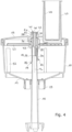
- the carrier sleeve 32 has a funnel section 45 tapering in the direction of the first carrier sleeve end 33 in a funnel-like manner, wherein a receiving slot 46 for a comminution tool 22 is formed at a lower end of the funnel section 45, and wherein in the operating state structure a comminution tool 22 is inserted into the receiving slot 46 ( Fig.1 ).
- the crushing tool 22 is a cutting disk (see e.g. Fig.3 ), which is rotationally fixedly connected to a cutting disk carrier sleeve 49 that projects through the cutting disk in a centered manner, wherein the cutting disk carrier sleeve 49 is detachably pushed onto the carrier sleeve 32 in the operating state and is secured against axial displacement in relation to the carrier shaft longitudinal axis TL by locking means 50 arranged on the carrier sleeve 32, and wherein the cutting disk carrier sleeve 49 is rotationally fixedly connected to the carrier sleeve 32 when pushed onto the latter.
- an anti-twisting device is arranged on an outer surface 53 of the collecting pot casing 13, which has a support flange 54 which, in the operating state, is supported on a tab 55 and/or a handle 56 arranged on the preparation pot lid 8 ( Figures 15 to 18 ). This provides a rotation lock for the collecting pot 10 relative to the preparation pot 3 or preparation pot lid 8.
- Figure 1 a partially sectioned schematic side view of a food processor arrangement according to the first embodiment of the invention, in which a food processor assembly and a shredding assembly are assembled to form an operating state structure.
- Figure 2 shows a perspective exploded view of a kitchen appliance arrangement according to the first embodiment of the invention.
- Fig.3 shows a perspective exploded view of the shredding assembly for a food processor arrangement according to the second embodiment of the invention.
- the shredding tool 22 is designed as a cutting disk.
- the filler neck 47 is also arranged at a different location on the collecting pot lid 15 compared to the first embodiment.
- Fig.4 shows the shredding assembly after Fig.3 (i.e. according to the second embodiment) in a partially sectioned schematic side view, but in an assembled state of the components of the shredding assembly.
- the Fig.5 shows the assembled shredding assembly from Fig.4 in an uncut side view.
- the Fig.6 shows an exploded view of the kitchen appliance arrangement according to the second embodiment.
- FIG. 7a shows a view of a collecting pot lid 15 of a shredding assembly which is part of a food processor arrangement according to the second embodiment of the invention.
- the filling nozzle 47 can be seen as well as the carrier sleeve 32 with its polygonal outer contour.
- Fig. 7b shows a view of a collecting pot 10 of a shredding assembly which is part of a food processor arrangement according to the first and second embodiments of the invention.
- the webs 52 and the support flange 54 including the nod 57 are particularly clearly visible.
- Fig. 7c shows a view of an adapter shaft 16 of a shredding assembly, which is part of a food processor arrangement according to the first and second embodiment of the invention.
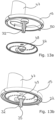
- FIG. 7d and 7e Views are shown of shredding tools in the form of cutting disks of a shredding assembly which is part of a food processor arrangement according to the second embodiment of the invention.
- the cutting disks can have different patterns (as required) of cutting edges 63. Openings are generally formed on the cutting edges through which the material to be shredded can fall in the direction of the collecting pot 10.
- Fig. 7f shows a view of a plunger 48, which is used in both embodiments.
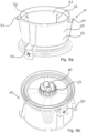
- FIG. 8a shows a perspective view of a collecting pot 10 of a shredding assembly, which is part of a food processor arrangement according to the first and second embodiment of the invention. Stop elements 64 can be clearly seen, which, as in Figure 14b and 15a shown as anchor points for on the collecting pot cover 15 serve as a contact wing 65. These contribute to securing the collecting pot cover 15 against rotation relative to the collecting pot 10.
- the Fig. 8b shows a perspective view of the collecting pot 10 after Figure 8a from its underside together with the fastening collars 28 arranged thereon and the associated fastening webs 60.
- Fig.9 shows a view of an alternative design of the Figure 8b shown fastening collar 28.
- the fastening collar 28 is cylindrical and continuous, but not in the form of lined-up fastening webs 60.
- Fig.10 shows a perspective view of the insertion of the adapter shaft 16 into a preparation pot 3 in a food processor arrangement according to the first and second embodiments of the invention.
- Fig. 11 shows a perspective view of the placement of the collecting pot 10 on the preparation pot 3 in a food processor arrangement according to the first and second embodiments of the invention.
- Fig. 12 shows a perspective view of an arrangement of preparation pot 3, inserted adapter shaft 16, collecting pot 10 placed on the preparation pot 3, and collecting pot lid 15 in a food processor arrangement according to the second embodiment of the invention.
- Fig.10 shows a perspective view of the insertion of the adapter shaft 16 into a preparation pot 3 in a food processor arrangement according to the first and second embodiments of the invention.
- Fig. 11 shows a perspective view of the placement of the collecting pot 10 on the preparation pot 3 in a food processor arrangement according to the first and second embodiments of the invention.
- Fig. 15a shows a perspective view of a kitchen appliance arrangement according to the second embodiment of the invention.
- Fig. 15b shows a side view of the kitchen machine arrangement after Fig. 15a
- Fig. 15c an enlarged view of a detail from Fig. 15b
- the support of the support flange 54 on the tab 55 can be clearly seen. This is also shown in the Figures 16a and 16b clearly visible.
- FIGS 17a,b and 18a,b show a perspective view of a kitchen appliance arrangement according to the second embodiment of the invention, wherein here a gripping of the cam 58 in relation to the tab 59 of the preparation pot lid 8 is shown.
- the cam 58 forms an axial lock and anti-twist lock.
- the anti-twisting and axial securing of the collecting pot 10 in relation to the preparation pot can be designed analogously in both embodiments.
Landscapes
- Engineering & Computer Science (AREA)
- Mechanical Engineering (AREA)
- Food Science & Technology (AREA)
- Food-Manufacturing Devices (AREA)
Applications Claiming Priority (3)
| Application Number | Priority Date | Filing Date | Title |
|---|---|---|---|
| DE102022110290.4A DE102022110290B4 (de) | 2022-04-27 | 2022-04-27 | Küchenmaschinenanordnung |
| EP23700627.5A EP4287917B1 (fr) | 2022-04-27 | 2023-01-09 | Agencement de robot culinaire |
| PCT/EP2023/050331 WO2023208422A1 (fr) | 2022-04-27 | 2023-01-09 | Agencement de robot culinaire et ensemble hachoir pour robot culinaire |
Related Parent Applications (1)
| Application Number | Title | Priority Date | Filing Date |
|---|---|---|---|
| EP23700627.5A Division EP4287917B1 (fr) | 2022-04-27 | 2023-01-09 | Agencement de robot culinaire |
Publications (2)
| Publication Number | Publication Date |
|---|---|
| EP4393361A2 true EP4393361A2 (fr) | 2024-07-03 |
| EP4393361A3 EP4393361A3 (fr) | 2024-07-10 |
Family
ID=84982491
Family Applications (2)
| Application Number | Title | Priority Date | Filing Date |
|---|---|---|---|
| EP23700627.5A Active EP4287917B1 (fr) | 2022-04-27 | 2023-01-09 | Agencement de robot culinaire |
| EP24170497.2A Pending EP4393361A3 (fr) | 2022-04-27 | 2023-01-09 | Ensemble robot de cuisine et ensemble de broyage pour un robot de cuisine |
Family Applications Before (1)
| Application Number | Title | Priority Date | Filing Date |
|---|---|---|---|
| EP23700627.5A Active EP4287917B1 (fr) | 2022-04-27 | 2023-01-09 | Agencement de robot culinaire |
Country Status (8)
| Country | Link |
|---|---|
| US (1) | US20250082135A1 (fr) |
| EP (2) | EP4287917B1 (fr) |
| CN (2) | CN117320601A (fr) |
| AU (1) | AU2023261894B2 (fr) |
| DE (1) | DE102022110290B4 (fr) |
| ES (1) | ES2982136T3 (fr) |
| PL (1) | PL4287917T3 (fr) |
| WO (1) | WO2023208422A1 (fr) |
Citations (1)
| Publication number | Priority date | Publication date | Assignee | Title |
|---|---|---|---|---|
| EP3936014A1 (fr) | 2020-07-09 | 2022-01-12 | Vorwerk & Co. Interholding GmbH | Appareil de préparation des aliments permettant de couper les denrées alimentaires, accessoire de broyage et procédé |
Family Cites Families (20)
| Publication number | Priority date | Publication date | Assignee | Title |
|---|---|---|---|---|
| DE1241952B (de) * | 1964-07-25 | 1967-06-08 | Siemens Elektrogeraete Gmbh | Haushaltmaschine zum Zerkleinern von Lebensmitteln |
| DE7507736U (de) | 1974-03-26 | 1975-07-03 | Moulinex Sa | Elektrohaushaltsgerät mit aufsetzbarem Zusatz |
| GB1600082A (en) | 1977-06-06 | 1981-10-14 | Hobart Corp | Food processing apparatus |
| US4199112A (en) | 1978-10-25 | 1980-04-22 | General Electric Company | Processor and bidirectional cutting disc |
| DE8522117U1 (de) | 1985-08-01 | 1985-09-26 | Philips Patentverwaltung Gmbh, 2000 Hamburg | Küchengerät mit Rührbesen |
| JP3651685B2 (ja) | 2003-10-01 | 2005-05-25 | 弘培 金 | 家庭用おかゆ調理器およびそれを用いたおかゆの調理方法 |
| DE102009006041A1 (de) | 2009-01-24 | 2010-07-29 | Vorwerk & Co. Interholding Gmbh | Elektromotorisch betriebene Küchenmaschine |
| FR2955475B1 (fr) | 2010-01-22 | 2013-09-06 | Hameur Sa | Appareil multifonctionnel de traitement mecanique d'aliments |
| US8985010B2 (en) * | 2010-04-29 | 2015-03-24 | Whirlpool Corporation | Food processor with cutting blade assembly support |
| US9522399B2 (en) | 2012-03-09 | 2016-12-20 | Whirlpool Corporation | Food processor and adjustable cutting assembly |
| DE202012105011U1 (de) | 2012-12-21 | 2013-01-25 | Vorwerk & Co. Interholding Gmbh | Elektromotorisch betriebene Küchenmaschine |
| AT518073B1 (de) | 2016-03-25 | 2017-07-15 | Johann Innerhuber | Küchenmaschine |
| GB2552155B (en) | 2016-07-08 | 2021-08-18 | Kenwood Ltd | Food Processor |
| US11553819B2 (en) * | 2018-12-28 | 2023-01-17 | Vita-Mix Management Corporation | Autolayering blending system |
| AT522365B1 (de) | 2019-05-13 | 2020-10-15 | Innerhuber Johann | Aufsatzbehalter fur eine Kiichenmaschine |
| GB2591228B (en) * | 2020-01-07 | 2024-02-28 | Kenwood Ltd | Kitchen appliance, container, assembly and drive shaft extension therefor, and kits of parts |
| DE202020106270U1 (de) | 2020-11-02 | 2020-12-21 | Timo Plogstedt - Philip Bonmann GbR (vertretungsberechtigter Gesellschafter: Timo Plogstedt, 22767 Hamburg) | Saftpresse |
| WO2022188702A1 (fr) * | 2021-03-10 | 2022-09-15 | 九阳股份有限公司 | Robot de cuisine autonettoyant |
| DE202021105193U1 (de) * | 2021-09-27 | 2021-10-01 | Timo Plogstedt - Philip Bonmann oHG | Küchenmaschine und Häckslerergänzungsset für eine Küchenmaschine |
| DE202022002722U1 (de) | 2022-04-27 | 2023-03-07 | Wundermix Gmbh | Küchenmaschinenanordnung und Zerkleinerungsbaugruppe für eine Küchenmaschine |
-
2022
- 2022-04-27 DE DE102022110290.4A patent/DE102022110290B4/de active Active
-
2023
- 2023-01-09 ES ES23700627T patent/ES2982136T3/es active Active
- 2023-01-09 PL PL23700627.5T patent/PL4287917T3/pl unknown
- 2023-01-09 CN CN202380011584.XA patent/CN117320601A/zh active Pending
- 2023-01-09 US US18/552,818 patent/US20250082135A1/en active Pending
- 2023-01-09 EP EP23700627.5A patent/EP4287917B1/fr active Active
- 2023-01-09 AU AU2023261894A patent/AU2023261894B2/en active Active
- 2023-01-09 WO PCT/EP2023/050331 patent/WO2023208422A1/fr not_active Ceased
- 2023-01-09 EP EP24170497.2A patent/EP4393361A3/fr active Pending
- 2023-04-27 CN CN202321003940.7U patent/CN220832806U/zh not_active Expired - Fee Related
Patent Citations (1)
| Publication number | Priority date | Publication date | Assignee | Title |
|---|---|---|---|---|
| EP3936014A1 (fr) | 2020-07-09 | 2022-01-12 | Vorwerk & Co. Interholding GmbH | Appareil de préparation des aliments permettant de couper les denrées alimentaires, accessoire de broyage et procédé |
Also Published As
| Publication number | Publication date |
|---|---|
| EP4393361A3 (fr) | 2024-07-10 |
| PL4287917T3 (pl) | 2024-08-26 |
| EP4287917B1 (fr) | 2024-04-17 |
| EP4287917C0 (fr) | 2024-04-17 |
| CN117320601A (zh) | 2023-12-29 |
| DE102022110290A1 (de) | 2023-11-02 |
| US20250082135A1 (en) | 2025-03-13 |
| AU2023261894A1 (en) | 2024-01-18 |
| CN220832806U (zh) | 2024-04-26 |
| EP4287917A1 (fr) | 2023-12-13 |
| AU2023261894B2 (en) | 2024-08-29 |
| WO2023208422A1 (fr) | 2023-11-02 |
| DE102022110290B4 (de) | 2025-10-02 |
| ES2982136T3 (es) | 2024-10-14 |
Similar Documents
| Publication | Publication Date | Title |
|---|---|---|
| EP4026460B1 (fr) | Appareil de préparation des aliments permettant de couper les aliments, pièce rapportée de broyage et procédé | |
| DE2141813A1 (de) | Geraet fuer die zubereitung von nahrungsmitteln | |
| EP2015660A1 (fr) | Dispositif de traitement d'aliments | |
| EP3513696B1 (fr) | Robot de cuisine avec un élement de couverture pour un récipient de préparation | |
| EP1304064B1 (fr) | Robot ménager pour la préparation d'aliments | |
| EP4098155B1 (fr) | Insert d'extraction de jus pour un récipient de préparation, ainsi que robot de cuisine pourvu d'insert d'extraction de jus | |
| DE3873891T2 (de) | Schaelmaschine fuer obst und gemuese. | |
| DE202022002722U1 (de) | Küchenmaschinenanordnung und Zerkleinerungsbaugruppe für eine Küchenmaschine | |
| EP4494536B1 (fr) | Appareil de préparation d'aliments pour couper des aliments, accessoire de broyage et procédé | |
| EP4287917B1 (fr) | Agencement de robot culinaire | |
| EP2877070B1 (fr) | Rape circulaire | |
| DE1219641B (de) | Zerkleinerungs-, insbesondere Schneidvorrichtung in Verbindung mit einer von Hand tragbaren elektromotorisch angetriebenen Kuechenmaschine | |
| EP2848171B1 (fr) | Composante et outil d'un appareil de cuisine | |
| EP4119016B1 (fr) | Dispositif de préparation des aliments pourvu d'un accessoire en plusieurs parties | |
| EP2845529B1 (fr) | Composante d'un appareil de cuisine | |
| DE202022104120U1 (de) | Schneidvorrichtung für ein Küchengerät | |
| DE102021124947A1 (de) | Ergänzungsset für ein Multifunktionsküchengerät, ein Multifunktionsküchengerät und ein Verfahren zum Bearbeiten von Schneidgut | |
| DE102021124950A1 (de) | Küchenmaschine und Häckslerergänzungsset für eine Küchenmaschine | |
| EP3488744B1 (fr) | Élément de mixeur plongeur, partie d'agrandissement pour un élément de mixeur plongeur et mixeur plongeur de taille variable | |
| EP3390929A1 (fr) | Dispositif de broyage d'au moins un morceau de produit congelé | |
| DE102023112369B4 (de) | Küchenmaschine mit einer Entsafterbaugruppe, sowie eine Entsafterbaugruppe | |
| DE4322280A1 (de) | Arbeitsbehälter für eine elektrisch betriebene Haushaltsküchenmaschine | |
| DE202021105578U1 (de) | Schälvorrichtung | |
| EP4291078A1 (fr) | Dispositif d'epluchage pour appareil de cuisine et appareil de cuisine comprenant le dispositif d'epluchage | |
| EP0695581A1 (fr) | Hachoir à viande |
Legal Events
| Date | Code | Title | Description |
|---|---|---|---|
| PUAI | Public reference made under article 153(3) epc to a published international application that has entered the european phase |
Free format text: ORIGINAL CODE: 0009012 |
|
| STAA | Information on the status of an ep patent application or granted ep patent |
Free format text: STATUS: THE APPLICATION HAS BEEN PUBLISHED |
|
| REG | Reference to a national code |
Ref country code: DE Ref legal event code: R079 Free format text: PREVIOUS MAIN CLASS: A47J0043060000 Ipc: A47J0043250000 |
|
| PUAL | Search report despatched |
Free format text: ORIGINAL CODE: 0009013 |
|
| AC | Divisional application: reference to earlier application |
Ref document number: 4287917 Country of ref document: EP Kind code of ref document: P |
|
| AK | Designated contracting states |
Kind code of ref document: A2 Designated state(s): AL AT BE BG CH CY CZ DE DK EE ES FI FR GB GR HR HU IE IS IT LI LT LU LV MC ME MK MT NL NO PL PT RO RS SE SI SK SM TR |
|
| AK | Designated contracting states |
Kind code of ref document: A3 Designated state(s): AL AT BE BG CH CY CZ DE DK EE ES FI FR GB GR HR HU IE IS IT LI LT LU LV MC ME MK MT NL NO PL PT RO RS SE SI SK SM TR |
|
| RIC1 | Information provided on ipc code assigned before grant |
Ipc: A47J 43/06 20060101ALI20240603BHEP Ipc: A47J 43/07 20060101ALI20240603BHEP Ipc: A47J 43/25 20060101AFI20240603BHEP |
|
| STAA | Information on the status of an ep patent application or granted ep patent |
Free format text: STATUS: REQUEST FOR EXAMINATION WAS MADE |
|
| 17P | Request for examination filed |
Effective date: 20250110 |