EP4393392A1 - Katheter mit distaler neigungsdetektion - Google Patents
Katheter mit distaler neigungsdetektion Download PDFInfo
- Publication number
- EP4393392A1 EP4393392A1 EP23219954.7A EP23219954A EP4393392A1 EP 4393392 A1 EP4393392 A1 EP 4393392A1 EP 23219954 A EP23219954 A EP 23219954A EP 4393392 A1 EP4393392 A1 EP 4393392A1
- Authority
- EP
- European Patent Office
- Prior art keywords
- signal
- magnetic
- frequency
- probe
- distal part
- Prior art date
- Legal status (The legal status is an assumption and is not a legal conclusion. Google has not performed a legal analysis and makes no representation as to the accuracy of the status listed.)
- Pending
Links
Images


Classifications
-
- A—HUMAN NECESSITIES
- A61—MEDICAL OR VETERINARY SCIENCE; HYGIENE
- A61B—DIAGNOSIS; SURGERY; IDENTIFICATION
- A61B5/00—Measuring for diagnostic purposes; Identification of persons
- A61B5/68—Arrangements of detecting, measuring or recording means, e.g. sensors, in relation to patient
- A61B5/6846—Arrangements of detecting, measuring or recording means, e.g. sensors, in relation to patient specially adapted to be brought in contact with an internal body part, i.e. invasive
- A61B5/6885—Monitoring or controlling sensor contact pressure
-
- A—HUMAN NECESSITIES
- A61—MEDICAL OR VETERINARY SCIENCE; HYGIENE
- A61B—DIAGNOSIS; SURGERY; IDENTIFICATION
- A61B5/00—Measuring for diagnostic purposes; Identification of persons
- A61B5/06—Devices, other than using radiation, for detecting or locating foreign bodies ; Determining position of diagnostic devices within or on the body of the patient
- A61B5/061—Determining position of a probe within the body employing means separate from the probe, e.g. sensing internal probe position employing impedance electrodes on the surface of the body
- A61B5/062—Determining position of a probe within the body employing means separate from the probe, e.g. sensing internal probe position employing impedance electrodes on the surface of the body using magnetic field
-
- A—HUMAN NECESSITIES
- A61—MEDICAL OR VETERINARY SCIENCE; HYGIENE
- A61B—DIAGNOSIS; SURGERY; IDENTIFICATION
- A61B18/00—Surgical instruments, devices or methods for transferring non-mechanical forms of energy to or from the body
-
- A—HUMAN NECESSITIES
- A61—MEDICAL OR VETERINARY SCIENCE; HYGIENE
- A61B—DIAGNOSIS; SURGERY; IDENTIFICATION
- A61B18/00—Surgical instruments, devices or methods for transferring non-mechanical forms of energy to or from the body
- A61B18/04—Surgical instruments, devices or methods for transferring non-mechanical forms of energy to or from the body by heating
- A61B18/12—Surgical instruments, devices or methods for transferring non-mechanical forms of energy to or from the body by heating by passing a current through the tissue to be heated, e.g. high-frequency current
- A61B18/1206—Generators therefor
-
- A—HUMAN NECESSITIES
- A61—MEDICAL OR VETERINARY SCIENCE; HYGIENE
- A61B—DIAGNOSIS; SURGERY; IDENTIFICATION
- A61B18/00—Surgical instruments, devices or methods for transferring non-mechanical forms of energy to or from the body
- A61B18/04—Surgical instruments, devices or methods for transferring non-mechanical forms of energy to or from the body by heating
- A61B18/12—Surgical instruments, devices or methods for transferring non-mechanical forms of energy to or from the body by heating by passing a current through the tissue to be heated, e.g. high-frequency current
- A61B18/14—Probes or electrodes therefor
- A61B18/1492—Probes or electrodes therefor having a flexible, catheter-like structure, e.g. for heart ablation
-
- A—HUMAN NECESSITIES
- A61—MEDICAL OR VETERINARY SCIENCE; HYGIENE
- A61B—DIAGNOSIS; SURGERY; IDENTIFICATION
- A61B34/00—Computer-aided surgery; Manipulators or robots specially adapted for use in surgery
- A61B34/20—Surgical navigation systems; Devices for tracking or guiding surgical instruments, e.g. for frameless stereotaxis
-
- A—HUMAN NECESSITIES
- A61—MEDICAL OR VETERINARY SCIENCE; HYGIENE
- A61B—DIAGNOSIS; SURGERY; IDENTIFICATION
- A61B5/00—Measuring for diagnostic purposes; Identification of persons
- A61B5/06—Devices, other than using radiation, for detecting or locating foreign bodies ; Determining position of diagnostic devices within or on the body of the patient
- A61B5/065—Determining position of the probe employing exclusively positioning means located on or in the probe, e.g. using position sensors arranged on the probe
-
- A—HUMAN NECESSITIES
- A61—MEDICAL OR VETERINARY SCIENCE; HYGIENE
- A61B—DIAGNOSIS; SURGERY; IDENTIFICATION
- A61B5/00—Measuring for diagnostic purposes; Identification of persons
- A61B5/24—Detecting, measuring or recording bioelectric or biomagnetic signals of the body or parts thereof
- A61B5/25—Bioelectric electrodes therefor
- A61B5/279—Bioelectric electrodes therefor specially adapted for particular uses
- A61B5/28—Bioelectric electrodes therefor specially adapted for particular uses for electrocardiography [ECG]
- A61B5/283—Invasive
- A61B5/287—Holders for multiple electrodes, e.g. electrode catheters for electrophysiological study [EPS]
-
- A—HUMAN NECESSITIES
- A61—MEDICAL OR VETERINARY SCIENCE; HYGIENE
- A61B—DIAGNOSIS; SURGERY; IDENTIFICATION
- A61B5/00—Measuring for diagnostic purposes; Identification of persons
- A61B5/68—Arrangements of detecting, measuring or recording means, e.g. sensors, in relation to patient
- A61B5/6846—Arrangements of detecting, measuring or recording means, e.g. sensors, in relation to patient specially adapted to be brought in contact with an internal body part, i.e. invasive
- A61B5/6847—Arrangements of detecting, measuring or recording means, e.g. sensors, in relation to patient specially adapted to be brought in contact with an internal body part, i.e. invasive mounted on an invasive device
- A61B5/6852—Catheters
- A61B5/6858—Catheters with a distal basket, e.g. expandable basket
-
- A—HUMAN NECESSITIES
- A61—MEDICAL OR VETERINARY SCIENCE; HYGIENE
- A61B—DIAGNOSIS; SURGERY; IDENTIFICATION
- A61B18/00—Surgical instruments, devices or methods for transferring non-mechanical forms of energy to or from the body
- A61B2018/00053—Mechanical features of the instrument of device
- A61B2018/00214—Expandable means emitting energy, e.g. by elements carried thereon
- A61B2018/00267—Expandable means emitting energy, e.g. by elements carried thereon having a basket shaped structure
-
- A—HUMAN NECESSITIES
- A61—MEDICAL OR VETERINARY SCIENCE; HYGIENE
- A61B—DIAGNOSIS; SURGERY; IDENTIFICATION
- A61B18/00—Surgical instruments, devices or methods for transferring non-mechanical forms of energy to or from the body
- A61B2018/00315—Surgical instruments, devices or methods for transferring non-mechanical forms of energy to or from the body for treatment of particular body parts
- A61B2018/00345—Vascular system
- A61B2018/00351—Heart
-
- A—HUMAN NECESSITIES
- A61—MEDICAL OR VETERINARY SCIENCE; HYGIENE
- A61B—DIAGNOSIS; SURGERY; IDENTIFICATION
- A61B18/00—Surgical instruments, devices or methods for transferring non-mechanical forms of energy to or from the body
- A61B2018/00315—Surgical instruments, devices or methods for transferring non-mechanical forms of energy to or from the body for treatment of particular body parts
- A61B2018/00434—Neural system
-
- A—HUMAN NECESSITIES
- A61—MEDICAL OR VETERINARY SCIENCE; HYGIENE
- A61B—DIAGNOSIS; SURGERY; IDENTIFICATION
- A61B18/00—Surgical instruments, devices or methods for transferring non-mechanical forms of energy to or from the body
- A61B2018/00571—Surgical instruments, devices or methods for transferring non-mechanical forms of energy to or from the body for achieving a particular surgical effect
- A61B2018/00577—Ablation
-
- A—HUMAN NECESSITIES
- A61—MEDICAL OR VETERINARY SCIENCE; HYGIENE
- A61B—DIAGNOSIS; SURGERY; IDENTIFICATION
- A61B18/00—Surgical instruments, devices or methods for transferring non-mechanical forms of energy to or from the body
- A61B2018/00571—Surgical instruments, devices or methods for transferring non-mechanical forms of energy to or from the body for achieving a particular surgical effect
- A61B2018/00613—Irreversible electroporation
-
- A—HUMAN NECESSITIES
- A61—MEDICAL OR VETERINARY SCIENCE; HYGIENE
- A61B—DIAGNOSIS; SURGERY; IDENTIFICATION
- A61B18/00—Surgical instruments, devices or methods for transferring non-mechanical forms of energy to or from the body
- A61B2018/00964—Features of probes
-
- A—HUMAN NECESSITIES
- A61—MEDICAL OR VETERINARY SCIENCE; HYGIENE
- A61B—DIAGNOSIS; SURGERY; IDENTIFICATION
- A61B18/00—Surgical instruments, devices or methods for transferring non-mechanical forms of energy to or from the body
- A61B18/04—Surgical instruments, devices or methods for transferring non-mechanical forms of energy to or from the body by heating
- A61B18/12—Surgical instruments, devices or methods for transferring non-mechanical forms of energy to or from the body by heating by passing a current through the tissue to be heated, e.g. high-frequency current
- A61B18/1206—Generators therefor
- A61B2018/1273—Generators therefor including multiple generators in one device
-
- A—HUMAN NECESSITIES
- A61—MEDICAL OR VETERINARY SCIENCE; HYGIENE
- A61B—DIAGNOSIS; SURGERY; IDENTIFICATION
- A61B18/00—Surgical instruments, devices or methods for transferring non-mechanical forms of energy to or from the body
- A61B18/04—Surgical instruments, devices or methods for transferring non-mechanical forms of energy to or from the body by heating
- A61B18/12—Surgical instruments, devices or methods for transferring non-mechanical forms of energy to or from the body by heating by passing a current through the tissue to be heated, e.g. high-frequency current
- A61B18/14—Probes or electrodes therefor
- A61B2018/1467—Probes or electrodes therefor using more than two electrodes on a single probe
-
- A—HUMAN NECESSITIES
- A61—MEDICAL OR VETERINARY SCIENCE; HYGIENE
- A61B—DIAGNOSIS; SURGERY; IDENTIFICATION
- A61B34/00—Computer-aided surgery; Manipulators or robots specially adapted for use in surgery
- A61B34/10—Computer-aided planning, simulation or modelling of surgical operations
- A61B2034/101—Computer-aided simulation of surgical operations
- A61B2034/105—Modelling of the patient, e.g. for ligaments or bones
-
- A—HUMAN NECESSITIES
- A61—MEDICAL OR VETERINARY SCIENCE; HYGIENE
- A61B—DIAGNOSIS; SURGERY; IDENTIFICATION
- A61B34/00—Computer-aided surgery; Manipulators or robots specially adapted for use in surgery
- A61B34/20—Surgical navigation systems; Devices for tracking or guiding surgical instruments, e.g. for frameless stereotaxis
- A61B2034/2046—Tracking techniques
- A61B2034/2051—Electromagnetic tracking systems
- A61B2034/2053—Tracking an applied voltage gradient
-
- A—HUMAN NECESSITIES
- A61—MEDICAL OR VETERINARY SCIENCE; HYGIENE
- A61B—DIAGNOSIS; SURGERY; IDENTIFICATION
- A61B90/00—Instruments, implements or accessories specially adapted for surgery or diagnosis and not covered by any of the groups A61B1/00 - A61B50/00, e.g. for luxation treatment or for protecting wound edges
- A61B90/06—Measuring instruments not otherwise provided for
- A61B2090/064—Measuring instruments not otherwise provided for for measuring force, pressure or mechanical tension
- A61B2090/065—Measuring instruments not otherwise provided for for measuring force, pressure or mechanical tension for measuring contact or contact pressure
Definitions
- the present disclosure relates to invasive medical devices, and specifically to methods and devices for sensing displacement of a distal part of a probe, such as a catheter, that is applied to the body of a patient.
- a catheter is inserted into a chamber of the heart and brought into contact with the inner heart wall.
- U.S. Patent 8,535,308 whose disclosure is incorporated herein by reference, describes a medical probe, which includes an insertion tube, having a longitudinal axis and having a distal end.
- a distal tip is disposed at the distal end of the insertion tube and is configured to be brought into contact with a body tissue.
- a joint couples the distal tip to the distal end of the insertion tube.
- a joint sensor contained within the probe, senses a position of the distal tip relative to the distal end of the insertion tube.
- the joint sensor includes first and second subassemblies, which are disposed within the probe on opposite, respective sides of the joint and each include one or more magnetic transducers.
- the magnetic position sensor comprises a magnetic transducer, i.e., a device that converts magnetic energy into an electrical signal, or vice versa.
- a magnetic field generator in proximity to the patient's body produces an alternating-current ("AC") or time-varying magnetic field within the body at a certain frequency, and the signals output by the magnetic transducer at this frequency are processed to calculate position coordinates of the distal part of the probe.
- the magnetic transducer comprises one or more coils; but alternatively, other types of transducers, such as Hall sensors, may be used for the present purposes.
- Some probes comprise a deflectable distal assembly.
- some cardiac catheters comprise a basket assembly at their distal end, with electrodes distributed along the spines of the basket assembly for contacting tissue within the heart.
- the magnetic transducer used for position sensing in these sorts of catheters is commonly located near the distal end of the catheter insertion tube, while the basket assembly extends distally away from the distal end of the insertion tube.
- the basket assembly may deflect transversely, relative to the axis of the insertion tube, due to force exerted by the basket assembly against the tissue. When the deflection is substantial, for example more than a few degrees, the position coordinates given by the magnetic transducer will not give an accurate reading of the locations of the electrodes on the basket assembly.
- Some probes with deflectable distal assemblies include a force sensor for measuring the force exerted by the distal assembly against tissue in the body.
- the sorts of cardiac catheters that were described above may comprise a joint between the distal end of the insertion tube and the basket assembly.
- the joint deforms in response to force exerted by the basket assembly against the tissue.
- magnetic transducers are disposed in the catheter on opposing sides of the joint.
- One of the transducers for example the transducer on the distal side of the joint, is driven to generate an AC magnetic field at a certain frequency, and the transducer (or transducers) on the other side of the joint outputs a signal at this same frequency in response to this field.
- Control circuitry processes the signal to calculated the deformation of the joint and thus find the magnitude and direction of the force.
- At least one of the magnetic transducers in the force sensor also serves as a position sensor, to sense the AC magnetic field that is produced by the magnetic field generator outside the patient's body.
- Control circuitry processes the signal component output by this magnetic transducer at the frequency of the magnetic field generator in order to calculate position coordinates of the distal part of the probe within the body.
- the magnetic transducer on the distal side of the joint when used for this purpose, it will deflect together with the deflectable distal assembly and thus will give an accurate reading of the positions of the electrodes notwithstanding the deflection.
- the signals obtained from the magnetic transducer in the force sensor may be used together with signals provided by a magnetic transducer in the distal end of the insertion tube.
- the control circuitry measures the amplitude of the signal component at this frequency and generates an interference cancellation signal of the same amplitude but opposite phase.
- the control circuitry may desirably measure the exact frequency and phase of the signal component at the force sensor frequency and apply this measurement in generating the interference cancellation signal.
- This interference cancellation signal is summed with the signal that is received from the magnetic transducer in the force sensor, so that what remains following summation is the signal component at the frequency of the magnetic field generator.
- the control circuitry processes this remaining signal component in order to calculate the position coordinates.
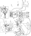
- Fig. 1 shows an example catheter-based electrophysiology mapping and ablation system 20.
- System 20 may include multiple catheters, which are percutaneously inserted by a physician 22 through the vascular system of a patient 23 into a chamber or vascular structure of a heart 24.
- a delivery sheath (not shown) is inserted into the left or right atrium near a desired location in heart 24.
- one or more catheters 26 are inserted through the delivery sheath so as to arrive at the desired location in heart 24.
- the multiple catheters may include catheters dedicated for sensing intracardiac electrogram (IEGM) signals, catheters dedicated for ablating, and/or catheters used for both sensing and ablating.
- the distal part of catheter 26 in the pictured example comprises a basket assembly 28.
- Physician 22 may manipulate catheter 26 to place basket assembly 28 in contact with the heart wall for sensing a target site in heart 24 and/or for ablating tissue at the target site.
- IEGM intracardiac electrogram
- Catheter 26 is an exemplary catheter that includes multiple electrodes 30 distributed over a plurality of spines 32 in basket assembly 28 and configured to sense IEGM signals and/or ablate myocardial tissue.
- Catheter 26 additionally includes one or more position sensors 34 embedded in the distal part of the catheter for tracking the position and orientation of basket assembly 28, as described further hereinbelow.
- position sensor 34 may comprise a magnetic position sensor including three magnetic coils for sensing three-dimensional (3D) position and orientation.
- Magnetic position sensors 70, 72 and 74 may be operated together with a location pad 36 including multiple magnetic coils 38 (shown as coils 38a, 38b, 38c in Fig. 3 ) configured to generate magnetic fields in a predefined working volume containing heart 24.
- the position of basket assembly 28 of catheter 26 may be tracked based on magnetic fields generated by location pad 36 and sensed by magnetic position sensor 34 (which may include three orthogonal coils). Details of magnetic position sensing technology that may be applied for this purpose are described, for example, in U.S.
- System 20 optionally includes one or more electrode patches 40 in contact with the skin of patient 23 to establish location references for location pad 36, as well as for impedance-based tracking of electrodes 30.
- impedance-based tracking electrical current is directed to electrodes 30 and sensed at electrode patches 40 so that the location of each electrode 30 can be triangulated via electrode patches 40. Details of this sort of impedance-based location tracking technology are described in U.S. Patent 7,536,218 ; 7,756,576 ; 7,848,787 ; 7,869,865 ; and 8,456,182 .
- a recorder 42 records and displays electrograms 44 captured by body-surface ECG electrodes 46 and intracardiac electrograms (IEGM) captured by electrodes 30 of catheter 26.
- Recorder 42 may include pacing capability for pacing the heart rhythm and/or may be electrically connected to a standalone pacer.
- a patient interface unit (PIU) 50 comprises an interface for electrical communication between catheters 26, other electrophysiological equipment, a power supply, and a workstation 52 for controlling operation of system 20.
- Electrophysiological equipment in system 20 may include for example, multiple catheters 26, location pad 36, body surface ECG electrodes 46, electrode patches 40, ablation energy generator 48, and recorder 42.
- PIU 50 additionally includes processing capability for implementing real-time computations of the position of the catheters and for processing ECG signals.
- Workstation 52 includes a memory and a processor, with appropriate operating software stored in the memory, and user interface capability. Workstation 52 may provide multiple functions, optionally including (1) modeling the endocardial anatomy in three-dimensions (3D) and rendering the model or an anatomical map 54 for display on a display device 56; (2) displaying on display device 56 activation sequences (or other data) compiled from recorded electrograms 44 in representative visual indicia or imagery superimposed on the rendered anatomical map 54; (3) displaying real-time location and orientation of one or more catheters within heart 24; and (4) displaying on display device 56 sites of interest such as places where ablation energy has been applied.
- a commercial product embodying elements of system 20 is the CARTO° 3 System, available from Biosense Webster, Inc. (31A Technology Drive, Irvine, CA 92618).
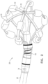
- FIG. 2 is a schematic pictorial illustration of basket assembly 28, in accordance with an example of the disclosure.
- Basket assembly 28 comprises multiple resilient spines 32, with electrodes 30 disposed along the spines.
- basket assembly 28 is shown as comprising six spines 32, in alternative embodiments the basket assembly may comprise a larger or smaller number of spines.
- Basket assembly 28 may comprise other components, as well (not shown in the figures), such as ultrasound transducers and temperature sensors. Electrodes 30, as well as these other components, are connected to wires (not shown) running through insertion tube 62 to the proximal end of catheter 26, where they connect to appropriate circuitry in PIU 50. Further details of the construction of basket assembly 28 are presented, for example, in U.S. Provisional Patent Application 63/336,094, filed April 4, 2022 (BIO6693), whose disclosure is incorporated herein by reference. Alternatively, other designs of the electrodes and spines may be used, as will be apparent to those skilled in the art after reading the present description.
- Fig. 3 is a schematic, sectional view of joint 60 and associated components in the distal part of catheter 26, showing details of the structure of the catheter in accordance with an example of the disclosure.
- Insertion tube 62 (extending along longitudinal axis L-L) is connected to a proximal portion 28a of basket assembly 28 by joint 60, as noted above. Insertion tube 62 and joint 60 are covered by a flexible, insulating material (which is cut away in Fig. 3 to expose the internal structure of the catheter).
- Joint 60 comprises a resilient coupling member 64.
- coupling member 64 has the form of a tubular piece of an elastic material, with a helical cut along a portion of its length.
- the coupling member may comprise a superelastic alloy, such as nickel titanium (Nitinol).
- Nitinol nickel titanium
- the helical cut causes the tubular piece to behave like a spring in response to forces exerted on basket assembly 28.
- the coupling member may comprise a coil spring or any other suitable sort of resilient component with the desired flexibility and strength characteristics.
- the joint is an integral part of insertion tube 62, and coupling member 64 may take the form of a cut in the insertion tube itself.
- the stiffness of coupling member 64 determines the range of relative movement between basket assembly 28 and insertion tube 62 in response to forces exerted on the basket assembly 28, for example due to pressure against the endocardium during an ablation procedure.
- Coupling member 64 is configured to permit deformation, including axial displacement (i.e., movement along the axis of insertion tube 62) and angular deflection of basket assembly 28, in proportion to the force on the basket assembly. Measurement of the displacement and deflection gives an indication of the force and thus helps to ensure that the correct force is applied during ablation.
- each AC magnetic field generator 38a, 38b, 38c provides respective and distinct AC magnetic fields in order for PIU 50 to triangulate the three distinct time varying second magnetic fields so as to arrive at a location in space.
- each coil may have three coils oriented in X, Y and Z planes so that the magnetic field generators external to the patient may have a total of nine (9) magnetic field coils and hence nine (9) different time-varying magnetic fields (e.g., frequencies) for location determination by the internal coils in the catheter.
- Example 4 The apparatus according to example 3, wherein the control circuitry is configured to calculate a deformation of the joint responsively to the first signal output by the second magnetic transducer at the first frequency, and to measure the force exerted by the distal part of the probe against the tissue based on the calculated deformation.
- Example 8 The apparatus according to any of the preceding examples, wherein the control circuitry is configured to cancel the interference by measuring an amplitude of the interference in the second signal at the first frequency, generating a third signal having the measured amplitude at the first frequency, and subtracting the third signal from the second signal.
- Example 13 The method according to example 12, wherein the first and second magnetic transducers respectively comprise first and second coils, and driving the first magnetic transducer comprising applying an AC electrical current at the first frequency to the first coil.
- Example 14 The method according to example 12, wherein the distal part of the probe comprises a joint, which is configured to deform in response to a force exerted by the distal part of the probe against tissue, and wherein the first and second magnetic transducers are disposed on opposing sides of the joint.
- Example 21 The method according to example 20, wherein the second signal is output by the first magnetic transducer while the first magnetic transducer is driven to generate the first AC magnetic field.
- the first magnetic transducer to is driven to generate a first AC magnetic field at a first frequency while the probe is inside the body.
- the magnetic field generator is driven to generate a second AC magnetic field at a second frequency.
- a disposition of the distal part of the probe is calculated by processing a first signal output by the second magnetic transducer at the first frequency.
- Position coordinates of the distal part of the probe are calculated by processing a component of a second signal output by one of the first and second magnetic transducers at the second frequency while canceling from the second signal interference at the first frequency.
Landscapes
- Health & Medical Sciences (AREA)
- Life Sciences & Earth Sciences (AREA)
- Engineering & Computer Science (AREA)
- Surgery (AREA)
- Public Health (AREA)
- General Health & Medical Sciences (AREA)
- Biomedical Technology (AREA)
- Heart & Thoracic Surgery (AREA)
- Medical Informatics (AREA)
- Molecular Biology (AREA)
- Animal Behavior & Ethology (AREA)
- Veterinary Medicine (AREA)
- Physics & Mathematics (AREA)
- Biophysics (AREA)
- Pathology (AREA)
- Nuclear Medicine, Radiotherapy & Molecular Imaging (AREA)
- Otolaryngology (AREA)
- Cardiology (AREA)
- Human Computer Interaction (AREA)
- Plasma & Fusion (AREA)
- Physiology (AREA)
- Robotics (AREA)
- Media Introduction/Drainage Providing Device (AREA)
- Surgical Instruments (AREA)
- Measurement And Recording Of Electrical Phenomena And Electrical Characteristics Of The Living Body (AREA)
Applications Claiming Priority (1)
| Application Number | Priority Date | Filing Date | Title |
|---|---|---|---|
| US18/091,347 US20240215853A1 (en) | 2022-12-29 | 2022-12-29 | Catheter with Distal Tilt Detection |
Publications (1)
| Publication Number | Publication Date |
|---|---|
| EP4393392A1 true EP4393392A1 (de) | 2024-07-03 |
Family
ID=89321915
Family Applications (1)
| Application Number | Title | Priority Date | Filing Date |
|---|---|---|---|
| EP23219954.7A Pending EP4393392A1 (de) | 2022-12-29 | 2023-12-22 | Katheter mit distaler neigungsdetektion |
Country Status (5)
| Country | Link |
|---|---|
| US (1) | US20240215853A1 (de) |
| EP (1) | EP4393392A1 (de) |
| JP (1) | JP2024096085A (de) |
| CN (1) | CN118266861A (de) |
| IL (1) | IL309723A (de) |
Citations (18)
| Publication number | Priority date | Publication date | Assignee | Title |
|---|---|---|---|---|
| US5443489A (en) | 1993-07-20 | 1995-08-22 | Biosense, Inc. | Apparatus and method for ablation |
| US5558091A (en) | 1993-10-06 | 1996-09-24 | Biosense, Inc. | Magnetic determination of position and orientation |
| US6172499B1 (en) | 1999-10-29 | 2001-01-09 | Ascension Technology Corporation | Eddy current error-reduced AC magnetic position measurement system |
| US6239724B1 (en) | 1997-12-30 | 2001-05-29 | Remon Medical Technologies, Ltd. | System and method for telemetrically providing intrabody spatial position |
| US6332089B1 (en) | 1996-02-15 | 2001-12-18 | Biosense, Inc. | Medical procedures and apparatus using intrabody probes |
| US6484118B1 (en) | 2000-07-20 | 2002-11-19 | Biosense, Inc. | Electromagnetic position single axis system |
| US6618612B1 (en) | 1996-02-15 | 2003-09-09 | Biosense, Inc. | Independently positionable transducers for location system |
| US6690963B2 (en) | 1995-01-24 | 2004-02-10 | Biosense, Inc. | System for determining the location and orientation of an invasive medical instrument |
| US6892091B1 (en) | 2000-02-18 | 2005-05-10 | Biosense, Inc. | Catheter, method and apparatus for generating an electrical map of a chamber of the heart |
| US7536218B2 (en) | 2005-07-15 | 2009-05-19 | Biosense Webster, Inc. | Hybrid magnetic-based and impedance-based position sensing |
| US7756576B2 (en) | 2005-08-26 | 2010-07-13 | Biosense Webster, Inc. | Position sensing and detection of skin impedance |
| US7848787B2 (en) | 2005-07-08 | 2010-12-07 | Biosense Webster, Inc. | Relative impedance measurement |
| US7869865B2 (en) | 2005-01-07 | 2011-01-11 | Biosense Webster, Inc. | Current-based position sensing |
| US20130096551A1 (en) * | 2007-10-08 | 2013-04-18 | Biosense Webster (Israel), Ltd. | Catheter with pressure sensing |
| US8437832B2 (en) | 2008-06-06 | 2013-05-07 | Biosense Webster, Inc. | Catheter with bendable tip |
| US8456182B2 (en) | 2008-09-30 | 2013-06-04 | Biosense Webster, Inc. | Current localization tracker |
| US8535308B2 (en) | 2007-10-08 | 2013-09-17 | Biosense Webster (Israel), Ltd. | High-sensitivity pressure-sensing probe |
| US20130303886A1 (en) * | 2012-05-09 | 2013-11-14 | Doron Moshe Ludwin | Locating a catheter sheath end point |
-
2022
- 2022-12-29 US US18/091,347 patent/US20240215853A1/en active Pending
-
2023
- 2023-12-22 EP EP23219954.7A patent/EP4393392A1/de active Pending
- 2023-12-25 IL IL309723A patent/IL309723A/en unknown
- 2023-12-28 CN CN202311834160.1A patent/CN118266861A/zh active Pending
- 2023-12-28 JP JP2023222373A patent/JP2024096085A/ja active Pending
Patent Citations (19)
| Publication number | Priority date | Publication date | Assignee | Title |
|---|---|---|---|---|
| US5443489A (en) | 1993-07-20 | 1995-08-22 | Biosense, Inc. | Apparatus and method for ablation |
| US5558091A (en) | 1993-10-06 | 1996-09-24 | Biosense, Inc. | Magnetic determination of position and orientation |
| US6690963B2 (en) | 1995-01-24 | 2004-02-10 | Biosense, Inc. | System for determining the location and orientation of an invasive medical instrument |
| US6618612B1 (en) | 1996-02-15 | 2003-09-09 | Biosense, Inc. | Independently positionable transducers for location system |
| US6332089B1 (en) | 1996-02-15 | 2001-12-18 | Biosense, Inc. | Medical procedures and apparatus using intrabody probes |
| US6788967B2 (en) | 1997-05-14 | 2004-09-07 | Biosense, Inc. | Medical diagnosis, treatment and imaging systems |
| US6239724B1 (en) | 1997-12-30 | 2001-05-29 | Remon Medical Technologies, Ltd. | System and method for telemetrically providing intrabody spatial position |
| US6172499B1 (en) | 1999-10-29 | 2001-01-09 | Ascension Technology Corporation | Eddy current error-reduced AC magnetic position measurement system |
| US6892091B1 (en) | 2000-02-18 | 2005-05-10 | Biosense, Inc. | Catheter, method and apparatus for generating an electrical map of a chamber of the heart |
| US6484118B1 (en) | 2000-07-20 | 2002-11-19 | Biosense, Inc. | Electromagnetic position single axis system |
| US7869865B2 (en) | 2005-01-07 | 2011-01-11 | Biosense Webster, Inc. | Current-based position sensing |
| US7848787B2 (en) | 2005-07-08 | 2010-12-07 | Biosense Webster, Inc. | Relative impedance measurement |
| US7536218B2 (en) | 2005-07-15 | 2009-05-19 | Biosense Webster, Inc. | Hybrid magnetic-based and impedance-based position sensing |
| US7756576B2 (en) | 2005-08-26 | 2010-07-13 | Biosense Webster, Inc. | Position sensing and detection of skin impedance |
| US20130096551A1 (en) * | 2007-10-08 | 2013-04-18 | Biosense Webster (Israel), Ltd. | Catheter with pressure sensing |
| US8535308B2 (en) | 2007-10-08 | 2013-09-17 | Biosense Webster (Israel), Ltd. | High-sensitivity pressure-sensing probe |
| US8437832B2 (en) | 2008-06-06 | 2013-05-07 | Biosense Webster, Inc. | Catheter with bendable tip |
| US8456182B2 (en) | 2008-09-30 | 2013-06-04 | Biosense Webster, Inc. | Current localization tracker |
| US20130303886A1 (en) * | 2012-05-09 | 2013-11-14 | Doron Moshe Ludwin | Locating a catheter sheath end point |
Also Published As
| Publication number | Publication date |
|---|---|
| US20240215853A1 (en) | 2024-07-04 |
| JP2024096085A (ja) | 2024-07-11 |
| CN118266861A (zh) | 2024-07-02 |
| IL309723A (en) | 2024-07-01 |
Similar Documents
| Publication | Publication Date | Title |
|---|---|---|
| KR100786547B1 (ko) | 심장의 전기적인 활동에 대한 빠른 맵핑 | |
| KR100789117B1 (ko) | 심실의 전기적 맵을 생성하기 위한 카테터, 방법 및 장치 | |
| CN112617842A (zh) | 3d心内活动演示 | |
| JP6752571B2 (ja) | カテーテル電極を備えた遠距離場非感受性の装置 | |
| EP4183342B1 (de) | Abbildungssystem mit echtzeit-elektrogrammüberlagerung | |
| EP4483802A1 (de) | System zur formverfolgung eines deformierten intrakorporalen objekts | |
| EP4566561A1 (de) | Torsionsüberwachung an einer distalen endanordnung | |
| EP4393392A1 (de) | Katheter mit distaler neigungsdetektion | |
| CN118252606A (zh) | 用于经由三角测量来标测组织接触的系统和方法 | |
| EP4570207A1 (de) | Lokale detektion der nähe eines katheters zu einem gewebe mit verbesserter räumlicher abdeckung | |
| US12594038B2 (en) | Estimation of contact force of catheter expandable assembly | |
| EP4473992A1 (de) | Drahtlose herzstimulation | |
| US20250204837A1 (en) | Providing a blood pool direction vector based on measured impedances | |
| EP4578388A1 (de) | Systeme und verfahren zur intrakardialen elektrogrammessung | |
| EP4393389B1 (de) | Systeme zur abbildung von gewebekontakt mittels triangulation | |
| US12419693B2 (en) | Applying ablation signals to both sides of tissue | |
| JP2025091393A (ja) | カテーテル組織近接度推定専用の参照電極 | |
| CN120053070A (zh) | 利用经胸廓超声引导进入心外膜袋 | |
| IL318020A (en) | Devices for Catheter Articulation Systems | |
| HK1064906A (en) | Mapping catheter |
Legal Events
| Date | Code | Title | Description |
|---|---|---|---|
| PUAI | Public reference made under article 153(3) epc to a published international application that has entered the european phase |
Free format text: ORIGINAL CODE: 0009012 |
|
| STAA | Information on the status of an ep patent application or granted ep patent |
Free format text: STATUS: THE APPLICATION HAS BEEN PUBLISHED |
|
| AK | Designated contracting states |
Kind code of ref document: A1 Designated state(s): AL AT BE BG CH CY CZ DE DK EE ES FI FR GB GR HR HU IE IS IT LI LT LU LV MC ME MK MT NL NO PL PT RO RS SE SI SK SM TR |
|
| STAA | Information on the status of an ep patent application or granted ep patent |
Free format text: STATUS: REQUEST FOR EXAMINATION WAS MADE |
|
| 17P | Request for examination filed |
Effective date: 20241219 |
|
| GRAP | Despatch of communication of intention to grant a patent |
Free format text: ORIGINAL CODE: EPIDOSNIGR1 |
|
| STAA | Information on the status of an ep patent application or granted ep patent |
Free format text: STATUS: GRANT OF PATENT IS INTENDED |
|
| INTG | Intention to grant announced |
Effective date: 20260219 |
|
| GRAS | Grant fee paid |
Free format text: ORIGINAL CODE: EPIDOSNIGR3 |
|
| GRAA | (expected) grant |
Free format text: ORIGINAL CODE: 0009210 |
|
| STAA | Information on the status of an ep patent application or granted ep patent |
Free format text: STATUS: THE PATENT HAS BEEN GRANTED |