EP4483802A1 - System zur formverfolgung eines deformierten intrakorporalen objekts - Google Patents
System zur formverfolgung eines deformierten intrakorporalen objekts Download PDFInfo
- Publication number
- EP4483802A1 EP4483802A1 EP24185677.2A EP24185677A EP4483802A1 EP 4483802 A1 EP4483802 A1 EP 4483802A1 EP 24185677 A EP24185677 A EP 24185677A EP 4483802 A1 EP4483802 A1 EP 4483802A1
- Authority
- EP
- European Patent Office
- Prior art keywords
- loop
- loops
- flexible
- electrically
- deformable portion
- Prior art date
- Legal status (The legal status is an assumption and is not a legal conclusion. Google has not performed a legal analysis and makes no representation as to the accuracy of the status listed.)
- Pending
Links
Images


Classifications
-
- A—HUMAN NECESSITIES
- A61—MEDICAL OR VETERINARY SCIENCE; HYGIENE
- A61B—DIAGNOSIS; SURGERY; IDENTIFICATION
- A61B5/00—Measuring for diagnostic purposes; Identification of persons
- A61B5/06—Devices, other than using radiation, for detecting or locating foreign bodies ; Determining position of diagnostic devices within or on the body of the patient
- A61B5/061—Determining position of a probe within the body employing means separate from the probe, e.g. sensing internal probe position employing impedance electrodes on the surface of the body
- A61B5/062—Determining position of a probe within the body employing means separate from the probe, e.g. sensing internal probe position employing impedance electrodes on the surface of the body using magnetic field
-
- A—HUMAN NECESSITIES
- A61—MEDICAL OR VETERINARY SCIENCE; HYGIENE
- A61B—DIAGNOSIS; SURGERY; IDENTIFICATION
- A61B18/00—Surgical instruments, devices or methods for transferring non-mechanical forms of energy to or from the body
- A61B18/04—Surgical instruments, devices or methods for transferring non-mechanical forms of energy to or from the body by heating
- A61B18/12—Surgical instruments, devices or methods for transferring non-mechanical forms of energy to or from the body by heating by passing a current through the tissue to be heated, e.g. high-frequency current
- A61B18/14—Probes or electrodes therefor
- A61B18/1492—Probes or electrodes therefor having a flexible, catheter-like structure, e.g. for heart ablation
-
- A—HUMAN NECESSITIES
- A61—MEDICAL OR VETERINARY SCIENCE; HYGIENE
- A61B—DIAGNOSIS; SURGERY; IDENTIFICATION
- A61B34/00—Computer-aided surgery; Manipulators or robots specially adapted for use in surgery
- A61B34/20—Surgical navigation systems; Devices for tracking or guiding surgical instruments, e.g. for frameless stereotaxis
-
- A—HUMAN NECESSITIES
- A61—MEDICAL OR VETERINARY SCIENCE; HYGIENE
- A61B—DIAGNOSIS; SURGERY; IDENTIFICATION
- A61B5/00—Measuring for diagnostic purposes; Identification of persons
- A61B5/24—Detecting, measuring or recording bioelectric or biomagnetic signals of the body or parts thereof
- A61B5/25—Bioelectric electrodes therefor
- A61B5/279—Bioelectric electrodes therefor specially adapted for particular uses
- A61B5/28—Bioelectric electrodes therefor specially adapted for particular uses for electrocardiography [ECG]
- A61B5/283—Invasive
- A61B5/287—Holders for multiple electrodes, e.g. electrode catheters for electrophysiological study [EPS]
-
- A—HUMAN NECESSITIES
- A61—MEDICAL OR VETERINARY SCIENCE; HYGIENE
- A61B—DIAGNOSIS; SURGERY; IDENTIFICATION
- A61B5/00—Measuring for diagnostic purposes; Identification of persons
- A61B5/68—Arrangements of detecting, measuring or recording means, e.g. sensors, in relation to patient
- A61B5/6846—Arrangements of detecting, measuring or recording means, e.g. sensors, in relation to patient specially adapted to be brought in contact with an internal body part, i.e. invasive
- A61B5/6847—Arrangements of detecting, measuring or recording means, e.g. sensors, in relation to patient specially adapted to be brought in contact with an internal body part, i.e. invasive mounted on an invasive device
- A61B5/6852—Catheters
-
- G—PHYSICS
- G01—MEASURING; TESTING
- G01B—MEASURING LENGTH, THICKNESS OR SIMILAR LINEAR DIMENSIONS; MEASURING ANGLES; MEASURING AREAS; MEASURING IRREGULARITIES OF SURFACES OR CONTOURS
- G01B7/00—Measuring arrangements characterised by the use of electric or magnetic techniques
- G01B7/004—Measuring arrangements characterised by the use of electric or magnetic techniques for measuring coordinates of points
-
- A—HUMAN NECESSITIES
- A61—MEDICAL OR VETERINARY SCIENCE; HYGIENE
- A61B—DIAGNOSIS; SURGERY; IDENTIFICATION
- A61B18/00—Surgical instruments, devices or methods for transferring non-mechanical forms of energy to or from the body
- A61B2018/00053—Mechanical features of the instrument of device
- A61B2018/0016—Energy applicators arranged in a two- or three dimensional array
-
- A—HUMAN NECESSITIES
- A61—MEDICAL OR VETERINARY SCIENCE; HYGIENE
- A61B—DIAGNOSIS; SURGERY; IDENTIFICATION
- A61B18/00—Surgical instruments, devices or methods for transferring non-mechanical forms of energy to or from the body
- A61B2018/00053—Mechanical features of the instrument of device
- A61B2018/00214—Expandable means emitting energy, e.g. by elements carried thereon
- A61B2018/0022—Balloons
-
- A—HUMAN NECESSITIES
- A61—MEDICAL OR VETERINARY SCIENCE; HYGIENE
- A61B—DIAGNOSIS; SURGERY; IDENTIFICATION
- A61B18/00—Surgical instruments, devices or methods for transferring non-mechanical forms of energy to or from the body
- A61B2018/00315—Surgical instruments, devices or methods for transferring non-mechanical forms of energy to or from the body for treatment of particular body parts
- A61B2018/00345—Vascular system
- A61B2018/00351—Heart
- A61B2018/00357—Endocardium
-
- A—HUMAN NECESSITIES
- A61—MEDICAL OR VETERINARY SCIENCE; HYGIENE
- A61B—DIAGNOSIS; SURGERY; IDENTIFICATION
- A61B18/00—Surgical instruments, devices or methods for transferring non-mechanical forms of energy to or from the body
- A61B2018/00571—Surgical instruments, devices or methods for transferring non-mechanical forms of energy to or from the body for achieving a particular surgical effect
- A61B2018/00577—Ablation
-
- A—HUMAN NECESSITIES
- A61—MEDICAL OR VETERINARY SCIENCE; HYGIENE
- A61B—DIAGNOSIS; SURGERY; IDENTIFICATION
- A61B18/00—Surgical instruments, devices or methods for transferring non-mechanical forms of energy to or from the body
- A61B2018/00636—Sensing and controlling the application of energy
- A61B2018/00773—Sensed parameters
- A61B2018/00839—Bioelectrical parameters, e.g. ECG, EEG
-
- A—HUMAN NECESSITIES
- A61—MEDICAL OR VETERINARY SCIENCE; HYGIENE
- A61B—DIAGNOSIS; SURGERY; IDENTIFICATION
- A61B34/00—Computer-aided surgery; Manipulators or robots specially adapted for use in surgery
- A61B34/20—Surgical navigation systems; Devices for tracking or guiding surgical instruments, e.g. for frameless stereotaxis
- A61B2034/2046—Tracking techniques
- A61B2034/2051—Electromagnetic tracking systems
-
- A—HUMAN NECESSITIES
- A61—MEDICAL OR VETERINARY SCIENCE; HYGIENE
- A61B—DIAGNOSIS; SURGERY; IDENTIFICATION
- A61B34/00—Computer-aided surgery; Manipulators or robots specially adapted for use in surgery
- A61B34/20—Surgical navigation systems; Devices for tracking or guiding surgical instruments, e.g. for frameless stereotaxis
- A61B2034/2046—Tracking techniques
- A61B2034/2061—Tracking techniques using shape-sensors, e.g. fiber shape sensors with Bragg gratings
-
- A—HUMAN NECESSITIES
- A61—MEDICAL OR VETERINARY SCIENCE; HYGIENE
- A61B—DIAGNOSIS; SURGERY; IDENTIFICATION
- A61B2562/00—Details of sensors; Constructional details of sensor housings or probes; Accessories for sensors
- A61B2562/02—Details of sensors specially adapted for in-vivo measurements
- A61B2562/0223—Magnetic field sensors
Definitions
- This invention relates generally to detecting location of a flexible object placed within a living body, and specifically to sensing multiple conductive elements on a flexible electrophysiology probe or device so as to track its shape and deformation in space in real-time.
- Position sensing systems have also been developed which utilize impedance-based measurements.
- impedance is measured between electrodes fixed to the intrabody object and electrodes placed on the body surface.
- the systems then derive the position of the intrabody object from the impedance measurements.
- Methods for impedance-based position sensing are disclosed, for example, in U.S. Patent No. 5,983,126 to Wittkampf , in U.S. Patent No. 6,456,864 to Swanson , and in U.S. Patent No. 5,944,022 to Nardella , all of which disclosures are incorporated herein by reference.
- Hybrid position sensing systems and methods which combine magnetic and electrical position sensing techniques are disclosed, for example, in U.S. Patent Publication No. 20070016007 to Govari .
- a magnetic position sensor provides an accurate position reference for calibrating less accurate, electrical impedance-based measurements.
- a hybrid probe such as a catheter, comprising a triaxial magnetic position sensor and one or more electrodes is used to correlate the magnetic position measurements with the impedance-based measurements.
- Systems of this sort alleviate the need for multiple magnetic position sensors, and thus benefit from both magnetic position sensing and impedance-based sensing.
- magnetic, impedance-based or hybrid position sensing provides only "point" location of the corresponding sensor and not of the 3-D configuration as a whole, especially as a structure with segments connected by joints.
- magnetic position sensors whether single axis or multi-axes, are rigid in structure, they are not suitable for mounting on flexible portions of catheters to detect flexion or deformation, including distal end assemblies that are flexible or those that bend at an interface with a shaft. Because magnetic position sensors are mounted on rigid portions of catheter shafts, they do not sense the change in position of distal assemblies due to bend. As such, magnetic position sensors are not typically used to detect deformations in distal assemblies, for example, due to bending or flexion when pressed against the wall of the heart chamber.
- An intrabody flexible probe adapted to deform when subjected to an external force includes one or more integrated electromagnetic (EM) loops of electrically-conductive elements that are responsive to one or more magnetic fields to provide electrical signals indicative of the position the probe and its shape in space including its deformation in real-time.
- the EM loops that may be carried on or embedded in the flexible distal assembly and/or the flexible shaft of the probe are configured to generate voltage signals in response to magnetic fluxes that induce currents through the EM loops.
- the voltage signal of the EM loop correspondingly changes in response to the deformation.
- a collection of such responsive voltage signals may enable a system configured to receive and process the voltage signals to determine location coordinates of the EM loops in a local coordinate system and track a shape representative of the flexible probe in real-time.
- an intrabody probe comprises a deformable portion; and a flexible electromagnetic loop positioned on the deformable portion, the flexible electromagnetic loop configured to generate an induced voltage in response to an external magnetic field.
- the intrabody probe further comprises a distal electrode assembly and the deformable portion includes a deformable portion of the distal electrode assembly.
- the intrabody probe further comprises a shaft and the deformation portion includes a portion of a shaft.
- the intrabody probe further comprises a distal electrode assembly, a shaft, and an interface therebetween, and the deformation includes a portion of the interface.
- the flexible electromagnetic loop includes an electrically conductive spine.
- the flexible electromagnetic loop includes an electrically-conductive coating.
- the flexible electromagnetic loop includes an electrical trace.
- the flexible electromagnetic loop includes a flex circuit.
- the flexible electromagnetic loop is configured to generate a different induced voltage when the deformable portion experiences a deformation that changes the flexible magnetic loop from a neutral configuration into a deformed configuration.
- the induced voltage is indicative of a location of the flexible electromagnetic loop.
- the flexible electromagnetic loop is configured to generate the induced voltage in response to a first external magnetic field at a first frequency and to generate a second induced voltage in response to a second external magnetic field at a second frequency.
- an intrabody probe comprises a deformable portion, and a plurality of flexible electromagnetic loops, each in a different position on the deformable portion, each flexible electromagnetic loop configured to generate a respective induced voltage in response to an external magnetic field.
- At least one of the flexible electromagnetic loop includes an electrically conductive spine.
- At least one of the flexible electromagnetic loop includes an electrically-conductive coating.
- At least one of the flexible electromagnetic loop includes an electrical trace.
- At least one of the flexible electromagnetic loop includes a flex circuit.
- the flexible electromagnetic loops are configured to generate induced voltages indicative of locations of the loops in a local coordinate system.
- the flexible electromagnetic loops are configured to generate induced voltages indicative of deformations of the loops in a local coordinate system when the deformable portion transitions from a neutral configuration to a deformed configuration.
- each of the plurality of flexible electromagnetic loops is configured to generate the respective induced voltage in response to a first external magnetic field at a first frequency and to generate a respective second induced voltage in response to a second external magnetic field at a second frequency.
- each of the plurality of flexible electromagnetic loops is configured to generate a respective induced voltage when subjected to an external force that causes deformation of the respective loop, and a collection of the respective induced voltages of the plurality of loops is representative of a deformed shape of the deformable portion.
- an intrabody probe comprises a deformable portion, and a first electrically-conductive element and a second electrically-conductive element, the first and second electrically-conductive elements configured as a flexible electromagnetic loop on the deformation portion.
- the intrabody probe further comprises a first terminal of the first electrically-conductive element configured to carry a first induced voltage when exposed to a magnetic field, a second terminal of the second electrically-conductive element configured to carry a second induced voltage when exposed to the magnetic field, and a connection point configured to provide a voltage difference between the first and second induced voltages.
- the probe includes an electrophysiology catheter with a flexible end effector, the flexible end effector including the deformable portion.
- the end effector includes first and second splines configured as the first and second electrically-conductive elements.
- the first and second electrically-conductive elements include first and second electrically-conductive coatings on the end effector.
- the intrabody probe further comprises a flexible printed circuit board affixed to the end effector, the printed circuit board including the first and second electronically-conductive elements.
- the first and second electrically-conductive elements are affixed to an outer surface of the shaft.
- the shaft includes a sidewall and the first and second electrically-conductive elements include first and second wires embedded in the sidewall.
- the first electrically-conductive element includes a nonlinear segment.
- At least the first electrically-conductive element extends circumferentially about the shaft.
- a system comprises a magnetic field generator configured to generate a magnetic field, and a catheter.
- the catheter comprises a deformable portion, a plurality of flexible electromagnetic loops, and at least a connection point.
- Each of the plurality of flexible electromagnetic loops is affixed to a different position on the deformation portion, with each loop including a first electrically-conductive element, a second electrically-conductive element, a first terminal of the first electrically-conductive element configured to carry a first induced voltage when exposed to the magnetic field, and a second terminal of the second electrically-conductive element configured to carry a second induced voltage when exposed to the magnetic field.
- the at least a connection point is configured to provide a voltage difference between the first and second induced voltages of each loop.
- the system further comprises a display, and a processor that is configured to (i) receive the voltage difference of each loop from the at least one connection point; (ii) determine coordinates of each loop relative to a local coordinate system; and (iii) drive the display to display a shape as a visual representation of the deformable portion based on a collection of the coordinates of each loop.
- the deformable portion includes electrodes
- the system further includes an RF generator configured to energize the electrodes for ablation of tissue.
- the deformable portion includes a flexible end effector.
- the deformable portion includes a flexible shaft.
- the first and second electrically-conductive elements include first and second electrically-conductive coatings on the end effector.
- the system further comprises a flexible printed circuit board affixed to the end effector and the printed circuit board includes the first and second electronically-conductive elements.
- the first and second electrically-conductive elements are affixed to an outer surface of the shaft.
- the shaft includes a sidewall and the first and second electrically-conductive elements include first and second wires embedded in the sidewall.
- the display displays the shape as a visual representation in real-time.
- a system comprises a magnetic field generator configured to generate a magnetic field, and a catheter.
- the catheter comprises a deformable portion, a plurality of flexible electromagnetic loops, and at least a first connection point.
- Each of the plurality of flexible electromagnetic loops is affixed to the deformation portion at a different position, each loop including a first electrically-conductive element, a second electrically-conductive element, a first terminal of the first electrically-conductive element configured to carry a first induced voltage when exposed to the magnetic field, and a second terminal of the second electrically-conductive element configured to carry a second induced voltage when exposed to the magnetic field.
- the at least a connection point is configured to provide a voltage difference between the first and second induced voltages of each loop.
- the system further comprises a display, and a processor that is configured to (i) receive the voltage difference of each loop from the at least one connection point; (ii) determine coordinates of each loop relative to a local coordinate system; (iii) identify a shape for the deformable portion based on a collection of the coordinates of each loop; and (iv) drive the display to display the shape as a visual representation of the deformable portion.
- the terms “about” or “approximately” for any numerical values or ranges indicate a suitable dimensional tolerance that allows the part or collection of components to function for its intended purpose as described herein. More specifically, “about” or “approximately” may refer to the range of values ⁇ 20% of the recited value, e.g., “about 90%” may refer to the range of values from 71% to 99%.
- the terms “patient,” “host,” “user,” and “subject” refer to any human or animal subject and are not intended to limit the systems or methods to human use, although use of the subject invention in a human patient represents a preferred embodiment.
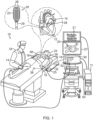
- System (10) includes multiple catheters, which are percutaneously inserted by a physician (24) through the patient's vascular system into a chamber or vascular structure of a heart (12).
- a delivery sheath catheter is inserted into the left or right atrium near a desired location in heart (12).
- one or more catheters may be inserted into the delivery sheath catheter so as to arrive at the desired location in heart (12).
- the plurality of catheters may include catheters dedicated for sensing Intracardiac Electrogram (IEGM) signals, catheters dedicated for ablating and/or catheters dedicated for both sensing and ablating.
- IEGM Intracardiac Electrogram
- Physician (24) may place a distal tip (28) of catheter (14) in contact with the heart wall for sensing a target site in heart (12).
- physician (24) may similarly place a distal end of an ablation catheter in contact with a target site for ablating tissue.
- Catheter (14) is an exemplary catheter that includes one and preferably multiple electrodes (26) optionally distributed over a plurality of splines (22) at distal tip (28) and configured to sense the IEGM signals.
- Catheter (14) may additionally include a position sensor (29) embedded in or near distal tip (28) for tracking position and orientation of distal tip (28).
- position sensor (29) is a magnetic based position sensor including three magnetic coils for sensing three-dimensional (3D) position and orientation.
- Magnetic based position sensor (29) may be operated together with a location pad (25) including a plurality of magnetic coils (32) configured to generate magnetic fields in a predefined working volume.
- Real time position of distal tip (28) of catheter (14) may be tracked based on magnetic fields generated with location pad (25) and sensed by magnetic based position sensor (29). Details of the magnetic based position sensing technology are described in U.S. Patent Nos. 5,5391,199 ; 5,443,489 ; 5,558,091 ; 6,172,499 ; 6,239,724 ; 6,332,089 ; 6,484,118 ; 6,618,612 ; 6,690,963 ; 6,788,967 ; 6,892,091 .
- System (10) includes one or more electrode patches (38) positioned for skin contact on patient (23) to establish location reference for location pad (25) as well as impedance-based tracking of electrodes (26).
- impedance-based tracking electrical current is directed to electrodes (26) and sensed at electrode skin patches (38) so that the location of each electrode can be triangulated via the electrode patches (38). Details of the impedance-based location tracking technology are described in US Patent Nos. 7,536,218 ; 7,756,576 ; 7,848,787 ; 7,869,865 ; and 8,456,182 .
- a recorder (11) records and displays electrograms (21) captured with body surface ECG electrodes (18) and intracardiac electrograms (IEGM) captured with electrodes (26) of catheter (14).
- Recorder (11) may include pacing capability for pacing the heart rhythm and/or may be electrically connected to a standalone pacer.
- System (10) may include an ablation energy generator (50) that is adapted to conduct ablative energy to one or more of electrodes at a distal tip of a catheter configured for ablating.
- Energy produced by ablation energy generator 50 may include, but is not limited to, radiofrequency (RF) energy or pulsed-field ablation (PFA) energy, including monopolar or bipolar high-voltage DC pulses as may be used to effect irreversible electroporation (IRE), or combinations thereof.
- RF radiofrequency
- PFA pulsed-field ablation
- IRE irreversible electroporation
- Patient interface unit (PIU) (30) is an interface configured to establish electrical communication between catheters, other electrophysiological equipment, power supply and a workstation (55) for controlling operation of system (10).
- Electrophysiological equipment of system (10) may include for example, multiple catheters, location pad (25), body surface ECG electrodes (18), electrode patches (38), ablation energy generator (50), and recorder (11).
- PIU (30) additionally includes processing capability for implementing real-time computations of location of the catheters and for performing ECG calculations.
- Workstation (55) includes memory, processor unit with memory or storage with appropriate operating software stored therein, and user interface capability. Workstation (55) may provide multiple functions, optionally including (1) modeling the endocardial anatomy in three-dimensions (3D) and rendering the model or anatomical map (20) for display on a display device 27, (2) displaying on display device (27) activation sequences (or other data) compiled from recorded electrograms (21) in representative visual indicia or imagery superimposed on the rendered anatomical map (20), (3) displaying real-time location and orientation of multiple catheters within the heart chamber, and (4) displaying on display device (27) sites of interest such as places where ablation energy has been applied.
- One commercial product embodying elements of the system (10) is available as the CARTOTM 3 System, available from Biosense Webster, Inc., 31A Technology Drive, Irvine, CA 92618.
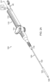
- a catheter assembly (100) includes handle assembly (110), catheter (120) extending distally from handle assembly (110), end effector (200) located at a distal end of catheter (120), and a deflection drive actuator (114) associated with handle assembly (110).
- Deflection drive actuator (114) is rotatable relative to a casing (112) of handle assembly (110) to thereby deflect end effector (200) and a distal portion of catheter (120) away from a central longitudinal axis (LA) defined by a proximal portion of catheter (120).
- LA central longitudinal axis
- Various suitable components that may be coupled with deflection drive actuator (114) and catheter (120) to provide such functionality will be apparent to those skilled in the art in view of the teachings herein.
- Catheter (120) includes an elongate flexible shaft (122) and an outer sheath (124). Shaft (122) is coaxially and slidably disposed within outer sheath (124). End effector (200) is positioned at the distal end of shaft (122). The proximal end of catheter (120) extends distally from a nozzle member (116) of handle assembly (110).
- outer sheath (124) is an integral component of catheter (120).
- sheath (124) is a component of another instrument, and catheter (120) is inserted into sheath (124). In either scenario, shaft (122) and an outer sheath (124) may transition between two arrangements, including a first arrangement as shown in FIG.
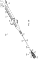
- outer sheath (124) is distally positioned in relation to shaft (122), such that end effector (200) is contained within outer sheath (124); and a second arrangement as shown in FIG. 2B where outer sheath (124) is proximally positioned in relation to shaft (122), such that end effector (200) is exposed relative to outer sheath (124).
- shaft (122) translates relative to handle assembly (110) to achieve the different longitudinal positioning relative to outer sheath (124).
- outer sheath (124) translates relative to handle assembly (110) to achieve the different longitudinal positioning relative to shaft (122).
- Catheter (120) and end effector (200) may be in the state shown in FIG. 2A when catheter (120) is introduced into the body of the patient (PA); and during transit from the insertion site to the targeted cardiovascular region within the patient (PA). Once catheter (120) and end effector (200) reach the targeted cardiovascular region within the patient (PA), outer sheath (124) may be retracted proximally to expose end effector (200), thereby allowing end effector (200) to achieve the expanded, deployed state shown in FIG. 2B
- end effector (200) is secured to the distal end of shaft (122) of catheter (120) via a proximal coupling member (230).
- End effector (200) of the present example includes a plurality of splines (210) that extend distally from the proximal connector 230.
- the proximal portion of each spline (210) extends distally and diverges outwardly away from the central longitudinal axis (LA) defined by a proximal portion of catheter (120).
- the longitudinally intermediate portion of each spline (210) is generally parallel with the central longitudinal axis (LA).
- each spline converges back toward the central longitudinal axis (LA).
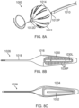
- a distal end of each spline is distally joined to a distal coupling (220) in the form of a ball ( FIG. 3 ), or alternatively, each spline can be formed from a linear spline that is bent into a U-shape such that the distal end and the proximal end converges at the proximal connector 230 ( FIG. 4 ).
- Each spline (210) may also include a plurality of electrodes (212) that are spaced apart from each other along the length of spine (210) ( FIG. 3 ). In some versions, electrodes (212) are operable to provide EP signals from tissue for EP mapping. In addition, or in the alternative, electrodes (212) may be operable to ablate tissue.
- Splines (210) may also include various other features, such as temperature sensors, etc.
- Splines (210) may be formed of a resilient material (e.g., nitinol, etc.) such that splines (210) may be resiliently biased to assume the configuration shown in FIG. 2B , FIG. 3 and FIG. 4 .
- end effector (200) defines a generally planar configuration when splines (210) are in the state shown, with the plane defined by end effector (200) extending along and transversely from the longitudinal axis (LA).
- Splines are also deformable such that splines may be contained within outer sheath (124) as shown in FIG. 2A . Splines may thus deform inwardly toward the longitudinal axis (LA), along the plane defined by end effector (200), to fit within sheath (124).
- splines may also deform along a direction that is transverse to the plane defined by end effector (200). Such deformation may occur as end effector (200) is pressed against tissue ( FIG. 5 ).
- the proximal coupling member (230) may take any suitable form.
- the coupling member (230) comprise a cylindrical plastic (e.g., polyether ether ketone (PEEK), etc.) component.
- the cylindrical plastic is flexible and deformable.
- the proximal ends of spines (210) may be fixedly secured to coupling member (230) via adhesive, overmolding, welding, epoxy, or in any other suitable fashion.
- the distal end of flexible shaft (122) may be fixedly secured to coupling member (230) via adhesive, overmolding, welding, epoxy, or in any other suitable fashion.
- Coupling member (230) of the present example also includes a ring electrode (240).
- ring electrode (240) is used to provide a reference signal from blood of a patient while electrodes (210) provide EP mapping signals from tissue of the patient.
- electrodes (210) provide EP mapping signals from tissue of the patient.
- ring electrode (240) may be used for any other suitable purpose(s).
- ring electrode (240) is omitted.
- the workstation 55 ( FIG. 1 ) is also operable to receive EM loop signals indicative of position and/or shape from the catheter assembly (100), as will be described in greater detail below.
- the workstation 55 is also operable to process the EM loop signals, including voltage signals, to thereby determine the position and/or shape of end effector (200) or other components of catheter assembly (100) within the patient (PA).
- Location pad (25) may include coils that generate alternating magnetic fields in a predetermined working volume that contains the heart (H). Each generator may also drive the coils at different frequencies.
- Display device (27) is coupled with the workstation (55) and is operable to render images of patient anatomy. Such images may be based on a set of preoperatively or intraoperatively obtained images (e.g., a CT or MRI scan, 3-D map, etc.).
- the views of patient anatomy provided through display device (27) may also change dynamically based on signals indicative of position and/or shape of catheter assembly (100), as described further below. For instance, as end effector (200) of catheter (120) moves within the patient (PA), corresponding position and/or shape data from catheter may cause the workstation (55) to update the patient anatomy views in display device (27) in real time to depict the regions of patient anatomy around end effector (200) as end effector (200) moves within the patient (PA).
- the workstation (55) may drive display device (27) to show locations of aberrant conductive tissue sites, as detected via EP mapping with end effector (200).
- the workstation (55) may drive display device (27) to superimpose the locations of aberrant conductive tissue sites on the images of the patient's anatomy, such as by superimposing an illuminated dot, a crosshair, or some other form of visual indication of aberrant conductive tissue sites.
- the workstation (55) may also advantageously drive display device (27) to superimpose the current position and/or shape of end effector (200), the shaft (122), including any deformation experience by the catheter (100) of its flexible portion, on the images of the patient's anatomy, such as by superimposing a graphical representation of such deformation.
- Such a superimposed visual indication may also move within the images of the patient anatomy on display device (27) in real time as the physician moves end effector (200) within the patient (PA), thereby providing real-time visual feedback to the operator about the position and/or shape of the catheter (100) within the patient (PA) as end effector (200) moves within the patient (PA).
- the images provided through display device (27) may thus effectively provide a video tracking the position and/or shape of the catheter and its deformation within the patient (PA), without necessarily having any optical instrumentation (i.e., cameras) viewing end effector (200).
- display device (27) may simultaneously visually indicate the locations of aberrant conductive tissue sites detected through the EP mapping.
- the physician (PH) may thus view display device (27) to observe the real time positioning and/or shape of the catheter elements in relation to the mapped aberrant conductive tissue sites and in relation to images of the adjacent anatomical structures in the patient (PA).
- the present example may include a fluid source of the present example includes a bag containing saline or some other suitable irrigation fluid.
- Conduit includes a flexible tube that is further coupled with a pump, which is operable to selectively drive fluid from fluid source to catheter assembly.
- conduit, fluid source, and pump are omitted entirely.
- end effector may be configured to communicate irrigation fluid from fluid source to the target site in the patient. Such irrigation may be provided in accordance with the teachings of any of the various patent references cited herein; or in any other suitable fashion as will be apparent to those skilled in the art in view of the teachings herein.
- the embodiments of the catheters shown in FIG.3 and FIG. 4 include one or more electromagnetic (EM) loops of electrically-conductive material that are formed on or otherwise integrated into one or more flexible portions of the catheter which can deform when subjected to an external force.
- EM electromagnetic
- FIG. 4 extending from a distal end of the shaft are splines (210) that form closed EM spline loops (L1, L2, L3).
- Each spline loop is formed from a linear spline that is curved or bent upon itself such that its distal end converges with its proximal end at the interface (213) with the distal end of the shaft.
- Each of the spline loop occupies a different position on the end effector (200) and each loop may generate a voltage signal based on the magnetic field flux through the respective loop at the location of the respective loop.
- the voltage reading for each loop may be provided at respective connection points (C1, C2, C3).
- each EM loop is subjected to one or more alternating magnetic fields around the heart (H) of the patient (PA) generated by one or more field generators (32) of location pad (25).
- Each loop may generate a voltage amount based on a magnetic field at the location of the loop.
- the console (12) with a processor receives voltage signals generated by each EM loops in response to the magnetic flux of at least one alternating magnetic field, where the voltage signals may be measured from a voltage contact that is part of the loop or external to the loop.
- each magnetic field can induce a respective voltage in each loop such that the processor can ascertain position and orientation of each loop in a defined 3-D coordinate system where a collection of such respective voltages of loops in different positions on the catheter.
- the processor may construct an electromagnetic map of the heart, based on any ECG signals (which indicate electrical activity of heart tissue) and the voltages induced in the loops (which indicate the respective locations of the loops and the sources of the ECG signals). Such a map may be displayed on the display 18.
- the loops in the flexible portion experience deformations as they transition from neutral configurations to deformed configurations, where such transitions changes their respective induced voltages as a result of changes in the respective magnetic fluxes.
- the catheter 100 has been maneuvered into contact with tissue such that the end effector 200 is no longer parallel with the longitudinal axis LA defined by the shaft 122 but extending at an angle with deformation at, for example, the interface 213 which transitions from a neutral configuration, as shown in FIG. 2B , to a deformed or bent configuration, as shown in FIG. 5 .
- each spline loop may undergo a deformation that impacts and alters the magnetic flux detected by each loop thereby changing the respective voltage signal induced by the magnetic fields.
- the voltage signals (and changes thereof) due to movement and deformation of the loops are measured at the respective frequencies to provide signals that are indicative of such movement and deformation.
- each spline (210) can form a loop with any other spline.
- spline (210a) may form a first loop (L1) via the distal coupling (220) with spline (210b), and spline (210a) may form a second loop (L2) via the distal coupling (220) with spline (210c), and spline (210b) and spline (210c) may form a third loop (L3) via the distal coupling (220).
- each of these loops may generate a distinct voltage signal based on the magnetic fields, generated by the field generators (32) of location pad (25), at the location of the end effector (200), with voltage readings provided at voltage measurement area or connection point (222).
- connection points 22 may be a voltage contact, such as a conductive pad or a wired connection, that is coupled to the guidance and drive system (10) via cable 30 through which the loop voltage signals are received and processed by the first driver module (14).
- a first terminal of a first conducting element carries a first voltage induced by the magnetic field(s) through the loop and a second terminal of a second conducting element carries a second voltage induced by the magnetic field through the loop.
- the pair of first and second conducting elements collectively carry to a differential amplifier (not shown) the voltage difference that is induced across the first and second conducting elements forming the loop.
- the outputs from the amplifier are representative of position and/or shape of the loop. It is understood that depending on the loops of interest, the voltage difference may be measured for any plurality of splines (and their respective conducting elements) that form the loops.
- the processor of the console (12) is operable to process the loop voltage signals to thereby determine the position of each loop, and the deformation of each loop, and therefore, collectively, the shape of the end effector and shaft on which the loops reside.
- the multiple loops collectively connect the overall structure of the end effector and the interface.
- the more loops configured at different locations on the catheter the more complete the system can track position and the full shape of the catheter in space.
- display device (27) of FIG. 1 can render images of patient anatomy based on a set of preoperatively or intraoperatively obtained images (e.g., a CT or MRI scan, 3-D map, etc.)
- the views of patient anatomy provided through display device (27) may also change dynamically based voltage signals from the loops of the catheter (100). For instance, as the end effector of FIG. 5 moves and/or deforms within the patient, the corresponding voltage signals may cause the processor of the console (12) to update the patient anatomy views in display device (27) in real time to depict the regions of patient anatomy around the end effector as the end effector moves or deforms within the patient.
- the workstation (55) may drive display device (27) to show locations of aberrant conductive tissue sites, as detected via electrophysiological (EP) mapping with the electrodes 212 on the end effector (200) or as otherwise detected (e.g., using a dedicated EP mapping catheter, etc.).
- EP electrophysiological
- the workstation (55) may also drive display device (27) to superimpose the current location of the end effector, along with its shape, on the images of the patient's anatomy, such as by superimposing an illuminated graphic representative of the shape or some other form of visual indication.
- Such a superimposed visual indication may also move within in the images of the patient anatomy on display device (27) in real time as the physician moves the end effector within the patient (PA), thereby providing real-time visual feedback to the operator about the position and shape of the end effector within the patient (PA) as the end effector moves within the patient, especially where the end effector is advanced into tissue wall which imparts an external force on the end effector to deform and change the shape of the end effector.
- the deformation(s) are also displayed in real-time.
- the images provided through display device (27) may thus effectively provide a video tracking the position and shape of the end effector within a patient (PA), without necessarily having any optical instrumentation (i.e., cameras) viewing the end effector.
- the display device (27) may simultaneously visually indicate the locations of aberrant conductive tissue sites detected through EP mapping.
- the physician (PH) may thus view display device (27) to observe the real time positioning and shape, including any deformation, of the end effector in relation to the mapped aberrant conductive tissue sites and in relation to images of the adjacent anatomical structures in the patient (PA).
- splines may be arranged to define any suitably shaped basket end effector (400), such as a spheroidal basket shown in FIG. 6.
- FIG. 6 shows an embodiment in which splines 412 electrically-conductive elements are printed onto the splines.
- each of the conductive elements may comprise electrically-conductive paint that is painted on the splines.
- the conducting elements comprise wires that are affixed to the surface of the splines.
- the splines themselves are constructed of electrically-conductive material.
- the basket end effector (400) includes a plurality of splines (412) whose proximal ends extend from a proximal coupling member (430) and whose distal ends converge at a hub (450). Because each spline is connected to every other spline via the hub (450), a combination of any two selected splines with their respective electrically-conductive elements can form an EM loop (e.g., L1, L2, L3) where the voltage difference induced by the magnetic field(s) across the first and second conducting elements forming the loop can be measured at a connection point (430) located on the proximal coupling member.
- an EM loop e.g., L1, L2, L3
- each loop (L1, L2, L3) need not be identical in shape and size to each other in that the pair of splines forming each loop need not be adjacent splines.
- An amplifier switch box (415) proximally of the basket end effector (400) receiving voltage signals via leads (417) can be configured to amplify the voltage difference between the selected splines of a loop and provide outputs to the processor of the console (12) via the cable (30), where such outputs advantageously indicate position and/or shape of the selected loop.
- a balloon end effector (500) has as electrically-conductive elements a flexible printed circuit board (PCB) (502) affixed to an outer surface (501) where the PCB (502) provides arrays (A1, A2) of electrodes (511) that are connected by leads (514) which form an EM loop (L).
- Signal outputs of the loop (L) are received by the processor of the console (12) via leads (517) extending proximally through catheter shaft (522) that are coupled to the cable (30), where the processor analyses the output for position and/or shape of the loop (L).
- the EM loop (L) includes a resistor (513) between the two arrays (A1, A2) which allows the electrodes (511) of the arrays to also function as ablation electrodes, as energized by, for example, an RF generator (507) connected proximally of the balloon end effector (500).
- a catheter (1000) includes a shaft (1010) and a deformable balloon (1012), configured with a plurality of flexible printed circuit boards (PCBs) (1014) disposed on an outer surface of the balloon (1012).
- PCBs flexible printed circuit boards
- each PCB (1014) is configured with a distal "leaf' portion (1016) and a proximal "stem” portion (1018) that lies along a respective longitudinal of the balloon (1012) to extend between distal and proximal ends (1022D, 1024P) of the balloon (1012).
- Each PCB (1014) includes a first or outer substrate (1026) with one or more electrical/electromagnetic sensors and a second or inner substrate (1028) with one or more electrical/electromagnetic sensors.
- the outer layer (1026) provides one or more electrodes configured for tissue proximity indications (TPI) via impedance measurements, as described in U.S. Publication 2023/0028867 , titled Accurate Tissue Proximity; U.S. Publication 2022/0183748A1 , titled Accurate Tissue Proximity; U.S. Publication 2020/0177504A1 , titled Tissue Proximity Indication Based on a Subset of Electrodes; and U.S. Publication 2020/0129089 , titled Combined Active Current Location (ACL) and Tissue Proximity Indication (TPI) System, all contents of which are incorporated herein by reference.
- TPI tissue proximity indications
- the first layer (1026) provides on an outer-facing surface an outer trace electrode (1030) and the second layer (1028) provides on an inner-facing surface an inner electrode (1032), together which are configured for impedance measurement for TPI.
- the trace electrode (1030) is configured as a "fishbone" with a longitudinal portion (1013L) and lateral finger portions (1030F). The lateral finger portions increase circumferential or equatorial contact surface of the trace electrode while gaps between adjacent finger portions allow the balloon to deflate/inflate.
- the inner electrode (1032) is situated below the longitudinal portion (1013L).
- the second layer (1028) also provides one or more electromagnetic sensors that are configured as one or more EM loops (1034) that provide location orientation of the balloon (1012) and of balloon deformation in response to the magnetic field generators (32) of location pad (25) ( FIG. 1 ).
- balloon deformation including inflation and deflation
- EM loop(s) is used to measure pressure change within the balloon in indicating, for example, balloon contact with tissue, for example, with a pulmonary vein ostium.
- an EM loop (L) is configured to extend axially on an outer surface (623) of a catheter shaft (622) to detect bending or deformation of the shaft, especially at a location proximal of and adjacent to the end effector (600).
- the EM loop (L) is coupled to leads (617) such that EM loop signals are transmitted proximally through the shaft (622) and received by the processor of the console (12) via the cable (30).
- an EM loop (L) is configured with one or more nonlinear segments (LN) on an outer surface (723) of a catheter shaft (722) so as to minimize mechanical strain when the catheter shaft is bent.
- the nonlinear segments (LN) configured, for example, as zig-zags, can accommodate stretching and/or compression of conductive element(s) of the EM loop when the shaft (722) is deflected or otherwise deformed, such as when an end effector (700) comes into contact with tissue.
- leads (717) extend proximally through catheter shaft (722) and are coupled to the processor of the console (12) via the cable (30).
- multiple EM loops are each configured circumferentially around an outer surface (823) of a catheter shaft (822), each with a respective pair of leads (817A, 817B) that extend proximally through the shaft and are coupled to the processor of the console (12) via the cable (30).
- a plane defined by each EM loop is angularly off angularly offset from diameter D of the shaft (822) (see, for example, angle ⁇ and angle ⁇ ).
- the EM loops are overlapping, as shown in FIG. 8D, although it is understood that the EM loops may be nonoverlapping.
- a catheter shaft (922) has a sidewall (907) configured with embedded electrically-conductive element(s) (909), for example, electrically conductive wires (903) that extend continuous or electrically coupled in at least a portion of the shaft (922).
- the wires (903) may be configured in any suitable configuration, for example, in counter-clockwise, angularly-offset spirals extending distally and clockwise, oppositely angularly-offset spirals extending proximally, with ends that are coupled to the cable 30 for transmitting EM loop signals to the processor of the console (12).
- Coverage of the structure of the shaft (922) with a sufficient plurality of EM loops on the surface and/or in the interior of the shaft (922), each in a different position or location on the end effector, enables the processor to monitor and track not only the position and orientation but the overall shape of the shaft (922) and any deformation it undergoes.
- Structural electrically-conductive materials such as the splines or embedded wires may include, for example, copper, stainless steel, and nitinol. Materials having shape memory may be advantageous in maintaining contact between electrodes carried on the splines and tissue surface.
- the system obtains apparent coordinates representing an apparent shape of any of these catheter elements in a local coordinate system.
- the processor may then apply a model of the mechanical properties of any of these catheter elements to the apparent coordinates.
- the processor may then compute a cost function with respect to shapes that can be assumed by any of these catheter elements within the patient's body.
- the processor may then identify and select a shape for any of these deformed catheter element in response to the cost function.
- the processor may then generate a set of corrected coordinates representing a corrected shape of any of these catheter elements.
- the processor using the corrected coordinates may drive the display device (27) to display a more accurate representation of any of these catheter elements.
- the processor may apply a catheter mechanics algorithm that defines a catheter's parameter by combining characteristics known in advance, such as its neutral shape, bendability and/or flexibility, the dimensions of any of these catheter elements.
- a catheter mechanics algorithm is described in U.S. Publication No. 2021/0345902 , titled “Catheter Shape and Position Detection Using Flexible Magnetic Sensor," the entire disclosure of which is incorporated herein by reference.
Landscapes
- Health & Medical Sciences (AREA)
- Life Sciences & Earth Sciences (AREA)
- Engineering & Computer Science (AREA)
- Surgery (AREA)
- Physics & Mathematics (AREA)
- Veterinary Medicine (AREA)
- Public Health (AREA)
- General Health & Medical Sciences (AREA)
- Biomedical Technology (AREA)
- Heart & Thoracic Surgery (AREA)
- Medical Informatics (AREA)
- Molecular Biology (AREA)
- Animal Behavior & Ethology (AREA)
- Pathology (AREA)
- Biophysics (AREA)
- Nuclear Medicine, Radiotherapy & Molecular Imaging (AREA)
- Cardiology (AREA)
- Plasma & Fusion (AREA)
- Otolaryngology (AREA)
- Human Computer Interaction (AREA)
- General Physics & Mathematics (AREA)
- Robotics (AREA)
- Physiology (AREA)
- Surgical Instruments (AREA)
- Measurement And Recording Of Electrical Phenomena And Electrical Characteristics Of The Living Body (AREA)
Applications Claiming Priority (2)
| Application Number | Priority Date | Filing Date | Title |
|---|---|---|---|
| US202363524144P | 2023-06-29 | 2023-06-29 | |
| US18/758,437 US20250000574A1 (en) | 2023-06-29 | 2024-06-28 | System and method for shape tracking of intrabody object subject to deformation |
Publications (1)
| Publication Number | Publication Date |
|---|---|
| EP4483802A1 true EP4483802A1 (de) | 2025-01-01 |
Family
ID=91759362
Family Applications (1)
| Application Number | Title | Priority Date | Filing Date |
|---|---|---|---|
| EP24185677.2A Pending EP4483802A1 (de) | 2023-06-29 | 2024-07-01 | System zur formverfolgung eines deformierten intrakorporalen objekts |
Country Status (5)
| Country | Link |
|---|---|
| US (1) | US20250000574A1 (de) |
| EP (1) | EP4483802A1 (de) |
| JP (1) | JP2025010063A (de) |
| CN (1) | CN119214627A (de) |
| IL (1) | IL314018A (de) |
Families Citing this family (2)
| Publication number | Priority date | Publication date | Assignee | Title |
|---|---|---|---|---|
| CN119730804A (zh) | 2022-06-21 | 2025-03-28 | 阿尔普发医疗股份有限公司 | 用于肾去神经支配的设备和方法 |
| JP2025534208A (ja) | 2022-09-30 | 2025-10-15 | アルファ メディカル,インコーポレイテッド | 組織アブレーションのための装置及び方法 |
Citations (27)
| Publication number | Priority date | Publication date | Assignee | Title |
|---|---|---|---|---|
| US5391199A (en) | 1993-07-20 | 1995-02-21 | Biosense, Inc. | Apparatus and method for treating cardiac arrhythmias |
| US5433489A (en) | 1990-04-16 | 1995-07-18 | Smc Corporation | Pipe fitting |
| US5539119A (en) | 1990-06-05 | 1996-07-23 | Toray Industries, Inc. | Indole derivatives |
| US5558091A (en) | 1993-10-06 | 1996-09-24 | Biosense, Inc. | Magnetic determination of position and orientation |
| US5944022A (en) | 1997-04-28 | 1999-08-31 | American Cardiac Ablation Co. Inc. | Catheter positioning system |
| US5983126A (en) | 1995-11-22 | 1999-11-09 | Medtronic, Inc. | Catheter location system and method |
| US6172499B1 (en) | 1999-10-29 | 2001-01-09 | Ascension Technology Corporation | Eddy current error-reduced AC magnetic position measurement system |
| US6177792B1 (en) | 1996-03-26 | 2001-01-23 | Bisense, Inc. | Mutual induction correction for radiator coils of an objects tracking system |
| US6239724B1 (en) | 1997-12-30 | 2001-05-29 | Remon Medical Technologies, Ltd. | System and method for telemetrically providing intrabody spatial position |
| US6332089B1 (en) | 1996-02-15 | 2001-12-18 | Biosense, Inc. | Medical procedures and apparatus using intrabody probes |
| US6456864B1 (en) | 1994-10-11 | 2002-09-24 | Ep Technologies, Inc. | Systems and methods for guiding movable electrode elements within multiple-electrode structures |
| US6484118B1 (en) | 2000-07-20 | 2002-11-19 | Biosense, Inc. | Electromagnetic position single axis system |
| US6618612B1 (en) | 1996-02-15 | 2003-09-09 | Biosense, Inc. | Independently positionable transducers for location system |
| US6690963B2 (en) | 1995-01-24 | 2004-02-10 | Biosense, Inc. | System for determining the location and orientation of an invasive medical instrument |
| US6892091B1 (en) | 2000-02-18 | 2005-05-10 | Biosense, Inc. | Catheter, method and apparatus for generating an electrical map of a chamber of the heart |
| US20070016007A1 (en) | 2005-07-15 | 2007-01-18 | Assaf Govari | Hybrid magnetic-based and impedance-based position sensing |
| US20100066371A1 (en) * | 2008-09-12 | 2010-03-18 | Kamal Vij | Intrabody mri stacked flat loop antennas and related systems |
| US7756576B2 (en) | 2005-08-26 | 2010-07-13 | Biosense Webster, Inc. | Position sensing and detection of skin impedance |
| US7848787B2 (en) | 2005-07-08 | 2010-12-07 | Biosense Webster, Inc. | Relative impedance measurement |
| US7869865B2 (en) | 2005-01-07 | 2011-01-11 | Biosense Webster, Inc. | Current-based position sensing |
| US8456182B2 (en) | 2008-09-30 | 2013-06-04 | Biosense Webster, Inc. | Current localization tracker |
| US20200129089A1 (en) | 2018-10-25 | 2020-04-30 | Biosense Webster (Israel) Ltd. | Combined active current location (acl) and tissue proximity indication (tpi) system |
| US20200177504A1 (en) | 2017-08-31 | 2020-06-04 | Nicira, Inc. | Method for improving throughput for encapsulated network traffic |
| US20200289059A1 (en) * | 2015-12-23 | 2020-09-17 | Biosense Webster (Israel) Ltd. | Catheter Frame Pieces Used as Large Single Axis Sensors |
| US20210345902A1 (en) | 2020-05-05 | 2021-11-11 | Biosense Webster (Israel) Ltd. | Catheter shape and position detection using flexible magnetic sensor |
| US20220183748A1 (en) | 2020-12-16 | 2022-06-16 | Biosense Webster (Israel) Ltd. | Accurate tissue proximity |
| US20230028867A1 (en) | 2021-07-23 | 2023-01-26 | Biosense Webster (Israel) Ltd. | Accurate tissue proximity |
Family Cites Families (3)
| Publication number | Priority date | Publication date | Assignee | Title |
|---|---|---|---|---|
| US11642165B2 (en) * | 2018-06-29 | 2023-05-09 | Biosense Webster (Israel) Ltd. | Catheter with mechanically expandable element having flex circuit |
| US11850051B2 (en) * | 2019-04-30 | 2023-12-26 | Biosense Webster (Israel) Ltd. | Mapping grid with high density electrode array |
| US20220313353A1 (en) * | 2021-04-06 | 2022-10-06 | Acclarent, Inc. | Ent instrument with rf electrodes on wire frame |
-
2024
- 2024-06-28 US US18/758,437 patent/US20250000574A1/en active Pending
- 2024-06-30 IL IL314018A patent/IL314018A/en unknown
- 2024-07-01 JP JP2024106019A patent/JP2025010063A/ja active Pending
- 2024-07-01 EP EP24185677.2A patent/EP4483802A1/de active Pending
- 2024-07-10 CN CN202410919913.7A patent/CN119214627A/zh active Pending
Patent Citations (30)
| Publication number | Priority date | Publication date | Assignee | Title |
|---|---|---|---|---|
| US5433489A (en) | 1990-04-16 | 1995-07-18 | Smc Corporation | Pipe fitting |
| US5539119A (en) | 1990-06-05 | 1996-07-23 | Toray Industries, Inc. | Indole derivatives |
| US5391199A (en) | 1993-07-20 | 1995-02-21 | Biosense, Inc. | Apparatus and method for treating cardiac arrhythmias |
| US5443489A (en) | 1993-07-20 | 1995-08-22 | Biosense, Inc. | Apparatus and method for ablation |
| US5558091A (en) | 1993-10-06 | 1996-09-24 | Biosense, Inc. | Magnetic determination of position and orientation |
| US6456864B1 (en) | 1994-10-11 | 2002-09-24 | Ep Technologies, Inc. | Systems and methods for guiding movable electrode elements within multiple-electrode structures |
| US6690963B2 (en) | 1995-01-24 | 2004-02-10 | Biosense, Inc. | System for determining the location and orientation of an invasive medical instrument |
| US5983126A (en) | 1995-11-22 | 1999-11-09 | Medtronic, Inc. | Catheter location system and method |
| US6332089B1 (en) | 1996-02-15 | 2001-12-18 | Biosense, Inc. | Medical procedures and apparatus using intrabody probes |
| US6618612B1 (en) | 1996-02-15 | 2003-09-09 | Biosense, Inc. | Independently positionable transducers for location system |
| US6177792B1 (en) | 1996-03-26 | 2001-01-23 | Bisense, Inc. | Mutual induction correction for radiator coils of an objects tracking system |
| US5944022A (en) | 1997-04-28 | 1999-08-31 | American Cardiac Ablation Co. Inc. | Catheter positioning system |
| US6788967B2 (en) | 1997-05-14 | 2004-09-07 | Biosense, Inc. | Medical diagnosis, treatment and imaging systems |
| US6239724B1 (en) | 1997-12-30 | 2001-05-29 | Remon Medical Technologies, Ltd. | System and method for telemetrically providing intrabody spatial position |
| US6172499B1 (en) | 1999-10-29 | 2001-01-09 | Ascension Technology Corporation | Eddy current error-reduced AC magnetic position measurement system |
| US6892091B1 (en) | 2000-02-18 | 2005-05-10 | Biosense, Inc. | Catheter, method and apparatus for generating an electrical map of a chamber of the heart |
| US6484118B1 (en) | 2000-07-20 | 2002-11-19 | Biosense, Inc. | Electromagnetic position single axis system |
| US7869865B2 (en) | 2005-01-07 | 2011-01-11 | Biosense Webster, Inc. | Current-based position sensing |
| US7848787B2 (en) | 2005-07-08 | 2010-12-07 | Biosense Webster, Inc. | Relative impedance measurement |
| US7536218B2 (en) | 2005-07-15 | 2009-05-19 | Biosense Webster, Inc. | Hybrid magnetic-based and impedance-based position sensing |
| US20070016007A1 (en) | 2005-07-15 | 2007-01-18 | Assaf Govari | Hybrid magnetic-based and impedance-based position sensing |
| US7756576B2 (en) | 2005-08-26 | 2010-07-13 | Biosense Webster, Inc. | Position sensing and detection of skin impedance |
| US20100066371A1 (en) * | 2008-09-12 | 2010-03-18 | Kamal Vij | Intrabody mri stacked flat loop antennas and related systems |
| US8456182B2 (en) | 2008-09-30 | 2013-06-04 | Biosense Webster, Inc. | Current localization tracker |
| US20200289059A1 (en) * | 2015-12-23 | 2020-09-17 | Biosense Webster (Israel) Ltd. | Catheter Frame Pieces Used as Large Single Axis Sensors |
| US20200177504A1 (en) | 2017-08-31 | 2020-06-04 | Nicira, Inc. | Method for improving throughput for encapsulated network traffic |
| US20200129089A1 (en) | 2018-10-25 | 2020-04-30 | Biosense Webster (Israel) Ltd. | Combined active current location (acl) and tissue proximity indication (tpi) system |
| US20210345902A1 (en) | 2020-05-05 | 2021-11-11 | Biosense Webster (Israel) Ltd. | Catheter shape and position detection using flexible magnetic sensor |
| US20220183748A1 (en) | 2020-12-16 | 2022-06-16 | Biosense Webster (Israel) Ltd. | Accurate tissue proximity |
| US20230028867A1 (en) | 2021-07-23 | 2023-01-26 | Biosense Webster (Israel) Ltd. | Accurate tissue proximity |
Non-Patent Citations (1)
| Title |
|---|
| WANG WEI: "Magnetic Resonance-guided Active Catheter Tracking", MAGNETIC RESONANCE IMAGING CLINICS OF NORTH AMERICA, vol. 23, no. 4, 6 July 2015 (2015-07-06), US, pages 579 - 589, XP055833720, ISSN: 1064-9689, Retrieved from the Internet <URL:http://dx.doi.org/10.1016/j.mric.2015.05.009> DOI: 10.1016/j.mric.2015.05.009 * |
Also Published As
| Publication number | Publication date |
|---|---|
| JP2025010063A (ja) | 2025-01-20 |
| IL314018A (en) | 2025-01-01 |
| US20250000574A1 (en) | 2025-01-02 |
| CN119214627A (zh) | 2024-12-31 |
Similar Documents
| Publication | Publication Date | Title |
|---|---|---|
| EP1743575B1 (de) | Hybrid-Positionsbestimmung auf Impedanz- und Magnetbasis | |
| US7869865B2 (en) | Current-based position sensing | |
| EP3254614B1 (de) | Multifunktionelle leitende elemente für einen katheter | |
| EP2737869B1 (de) | Vorrichtung zur Standortmessung unter Verwendung eines lokalen Koordinatensystems | |
| EP4183342B1 (de) | Abbildungssystem mit echtzeit-elektrogrammüberlagerung | |
| EP4483802A1 (de) | System zur formverfolgung eines deformierten intrakorporalen objekts | |
| EP4205653B1 (de) | Intuitives mapping-system | |
| US12539084B2 (en) | Spiral sensor for physiologic signal measurement with position and tissue proximity indication | |
| CN120093409A (zh) | 监测远侧端部组件上的扭转 | |
| CN118252606A (zh) | 用于经由三角测量来标测组织接触的系统和方法 | |
| EP4393392A1 (de) | Katheter mit distaler neigungsdetektion | |
| EP4393389B1 (de) | Systeme zur abbildung von gewebekontakt mittels triangulation | |
| EP4458264A1 (de) | Spiralsensor zur messung physiologischer signale mit positions- und gewebenäherungsanzeige |
Legal Events
| Date | Code | Title | Description |
|---|---|---|---|
| PUAI | Public reference made under article 153(3) epc to a published international application that has entered the european phase |
Free format text: ORIGINAL CODE: 0009012 |
|
| STAA | Information on the status of an ep patent application or granted ep patent |
Free format text: STATUS: THE APPLICATION HAS BEEN PUBLISHED |
|
| AK | Designated contracting states |
Kind code of ref document: A1 Designated state(s): AL AT BE BG CH CY CZ DE DK EE ES FI FR GB GR HR HU IE IS IT LI LT LU LV MC ME MK MT NL NO PL PT RO RS SE SI SK SM TR |
|
| STAA | Information on the status of an ep patent application or granted ep patent |
Free format text: STATUS: REQUEST FOR EXAMINATION WAS MADE |
|
| 17P | Request for examination filed |
Effective date: 20250520 |
|
| STAA | Information on the status of an ep patent application or granted ep patent |
Free format text: STATUS: EXAMINATION IS IN PROGRESS |
|
| 17Q | First examination report despatched |
Effective date: 20251223 |