EP4393406A1 - Système d'imagerie et procédé d'examen radiographique - Google Patents
Système d'imagerie et procédé d'examen radiographique Download PDFInfo
- Publication number
- EP4393406A1 EP4393406A1 EP22880277.3A EP22880277A EP4393406A1 EP 4393406 A1 EP4393406 A1 EP 4393406A1 EP 22880277 A EP22880277 A EP 22880277A EP 4393406 A1 EP4393406 A1 EP 4393406A1
- Authority
- EP
- European Patent Office
- Prior art keywords
- ray source
- detector
- source assembly
- assembly
- imaging
- Prior art date
- Legal status (The legal status is an assumption and is not a legal conclusion. Google has not performed a legal analysis and makes no representation as to the accuracy of the status listed.)
- Granted
Links
Images



Classifications
-
- G—PHYSICS
- G06—COMPUTING OR CALCULATING; COUNTING
- G06T—IMAGE DATA PROCESSING OR GENERATION, IN GENERAL
- G06T7/00—Image analysis
- G06T7/0002—Inspection of images, e.g. flaw detection
- G06T7/0012—Biomedical image inspection
-
- A—HUMAN NECESSITIES
- A61—MEDICAL OR VETERINARY SCIENCE; HYGIENE
- A61B—DIAGNOSIS; SURGERY; IDENTIFICATION
- A61B6/00—Apparatus or devices for radiation diagnosis; Apparatus or devices for radiation diagnosis combined with radiation therapy equipment
- A61B6/02—Arrangements for diagnosis sequentially in different planes; Stereoscopic radiation diagnosis
- A61B6/03—Computed tomography [CT]
- A61B6/032—Transmission computed tomography [CT]
-
- A—HUMAN NECESSITIES
- A61—MEDICAL OR VETERINARY SCIENCE; HYGIENE
- A61B—DIAGNOSIS; SURGERY; IDENTIFICATION
- A61B6/00—Apparatus or devices for radiation diagnosis; Apparatus or devices for radiation diagnosis combined with radiation therapy equipment
- A61B6/02—Arrangements for diagnosis sequentially in different planes; Stereoscopic radiation diagnosis
- A61B6/027—Arrangements for diagnosis sequentially in different planes; Stereoscopic radiation diagnosis characterised by the use of a particular data acquisition trajectory, e.g. helical or spiral
-
- A—HUMAN NECESSITIES
- A61—MEDICAL OR VETERINARY SCIENCE; HYGIENE
- A61B—DIAGNOSIS; SURGERY; IDENTIFICATION
- A61B6/00—Apparatus or devices for radiation diagnosis; Apparatus or devices for radiation diagnosis combined with radiation therapy equipment
- A61B6/40—Arrangements for generating radiation specially adapted for radiation diagnosis
- A61B6/4007—Arrangements for generating radiation specially adapted for radiation diagnosis characterised by using a plurality of source units
-
- A—HUMAN NECESSITIES
- A61—MEDICAL OR VETERINARY SCIENCE; HYGIENE
- A61B—DIAGNOSIS; SURGERY; IDENTIFICATION
- A61B6/00—Apparatus or devices for radiation diagnosis; Apparatus or devices for radiation diagnosis combined with radiation therapy equipment
- A61B6/40—Arrangements for generating radiation specially adapted for radiation diagnosis
- A61B6/4007—Arrangements for generating radiation specially adapted for radiation diagnosis characterised by using a plurality of source units
- A61B6/4014—Arrangements for generating radiation specially adapted for radiation diagnosis characterised by using a plurality of source units arranged in multiple source-detector units
-
- A—HUMAN NECESSITIES
- A61—MEDICAL OR VETERINARY SCIENCE; HYGIENE
- A61B—DIAGNOSIS; SURGERY; IDENTIFICATION
- A61B6/00—Apparatus or devices for radiation diagnosis; Apparatus or devices for radiation diagnosis combined with radiation therapy equipment
- A61B6/42—Arrangements for detecting radiation specially adapted for radiation diagnosis
- A61B6/4275—Arrangements for detecting radiation specially adapted for radiation diagnosis using a detector unit almost surrounding the patient, e.g. more than 180°
-
- A—HUMAN NECESSITIES
- A61—MEDICAL OR VETERINARY SCIENCE; HYGIENE
- A61B—DIAGNOSIS; SURGERY; IDENTIFICATION
- A61B6/00—Apparatus or devices for radiation diagnosis; Apparatus or devices for radiation diagnosis combined with radiation therapy equipment
- A61B6/54—Control of apparatus or devices for radiation diagnosis
-
- G—PHYSICS
- G01—MEASURING; TESTING
- G01N—INVESTIGATING OR ANALYSING MATERIALS BY DETERMINING THEIR CHEMICAL OR PHYSICAL PROPERTIES
- G01N23/00—Investigating or analysing materials by the use of wave or particle radiation, e.g. X-rays or neutrons, not covered by groups G01N3/00 – G01N17/00, G01N21/00 or G01N22/00
- G01N23/02—Investigating or analysing materials by the use of wave or particle radiation, e.g. X-rays or neutrons, not covered by groups G01N3/00 – G01N17/00, G01N21/00 or G01N22/00 by transmitting the radiation through the material
- G01N23/04—Investigating or analysing materials by the use of wave or particle radiation, e.g. X-rays or neutrons, not covered by groups G01N3/00 – G01N17/00, G01N21/00 or G01N22/00 by transmitting the radiation through the material and forming images of the material
- G01N23/046—Investigating or analysing materials by the use of wave or particle radiation, e.g. X-rays or neutrons, not covered by groups G01N3/00 – G01N17/00, G01N21/00 or G01N22/00 by transmitting the radiation through the material and forming images of the material using tomography, e.g. computed tomography [CT]
-
- G—PHYSICS
- G06—COMPUTING OR CALCULATING; COUNTING
- G06V—IMAGE OR VIDEO RECOGNITION OR UNDERSTANDING
- G06V10/00—Arrangements for image or video recognition or understanding
- G06V10/20—Image preprocessing
- G06V10/25—Determination of region of interest [ROI] or a volume of interest [VOI]
-
- A—HUMAN NECESSITIES
- A61—MEDICAL OR VETERINARY SCIENCE; HYGIENE
- A61B—DIAGNOSIS; SURGERY; IDENTIFICATION
- A61B6/00—Apparatus or devices for radiation diagnosis; Apparatus or devices for radiation diagnosis combined with radiation therapy equipment
- A61B6/52—Devices using data or image processing specially adapted for radiation diagnosis
- A61B6/5258—Devices using data or image processing specially adapted for radiation diagnosis involving detection or reduction of artifacts or noise
- A61B6/5282—Devices using data or image processing specially adapted for radiation diagnosis involving detection or reduction of artifacts or noise due to scatter
-
- G—PHYSICS
- G06—COMPUTING OR CALCULATING; COUNTING
- G06T—IMAGE DATA PROCESSING OR GENERATION, IN GENERAL
- G06T2207/00—Indexing scheme for image analysis or image enhancement
- G06T2207/10—Image acquisition modality
- G06T2207/10072—Tomographic images
- G06T2207/10081—Computed x-ray tomography [CT]
-
- G—PHYSICS
- G06—COMPUTING OR CALCULATING; COUNTING
- G06V—IMAGE OR VIDEO RECOGNITION OR UNDERSTANDING
- G06V2201/00—Indexing scheme relating to image or video recognition or understanding
- G06V2201/03—Recognition of patterns in medical or anatomical images
-
- G—PHYSICS
- G06—COMPUTING OR CALCULATING; COUNTING
- G06V—IMAGE OR VIDEO RECOGNITION OR UNDERSTANDING
- G06V2201/00—Indexing scheme relating to image or video recognition or understanding
- G06V2201/12—Acquisition of 3D measurements of objects
Definitions
- the present disclosure relates to a technical field of transmission imaging, and specifically relates to an imaging system for radiographic inspection.
- CT Computer Tomography
- the existing CT scanning system can include a dynamic spiral CT scanning system and a static CT scanning system according to the movement of the ray source relative to the object under inspection during the scanning process.
- the X-ray emission range of the ray source usually needs to cover the entire object under inspection, that is, the whole object under inspection is scanned and imaged, and these CT scanning systems only have a single target spot to emit X-rays at the same time.
- the existing static CT scanning system can use a single distributed ray source and one set of detector system, or can use multiple distributed ray sources and one common set of detector system.
- the one set of detector system can only receive X-rays from one target spot at the same time. Therefore, the scanning speed of these CT scanning systems is limited by the rotation speed of the slip ring used in the dynamic spiral scanning and the ray emission frequency of the ray source.
- the first ray source assembly further includes at least one second target spot, and a ray emission range of the second target spot is selected to be able to cover the inspection area, wherein the ray source control device is further configured such that the second target spot does not emit X-rays when the first target spot of the first ray source assembly emits X-rays, and that the first target spot does not emit X-rays when the second target spot of the first ray source assembly emits X-rays.
- the first ray source assembly includes a plurality of second target spots
- the ray source control device is configured such that the first ray source assembly can simultaneously emit X-rays from at least two second target spots to the inspection area, wherein among the at least two second target spots of the first ray source assembly simultaneously emitting X-rays to the inspection area, the first detector crystals corresponding to the ray emission ranges of any two second target spots do not coincide with each other.
- the number of second detector crystals of each second detector unit is equal to the number of first detector crystals of the corresponding first detector unit; or, the number of second detector crystals of each second detector unit is less than the number of first detector crystals of the corresponding first detector unit.
- the ray source control device is configured such that at least one first target spot of the first ray source assembly and at least one third target spot of the second ray source assembly simultaneously emit X-rays to the imaging area when the region of interest of the object under inspection is at least partially located in the imaging area, and wherein when at least one first target spot of the first ray source assembly and at least one third target spot of the second ray source assembly simultaneously emit X-rays to the imaging area, the detector crystals of the first detector assembly corresponding to the ray emission range of the first target spot of the first ray source assembly and the detector crystals of the first detector assembly corresponding to the ray emission range of the third target spot of the second ray source assembly do not coincide with each other.
- the step of the first ray source assembly emitting X-rays further includes: emitting X-rays from the second target spot of the first ray source assembly, and the ray emission range of the second target spot is selected to be able to cover the inspection area, wherein when the first target spot of the first ray source assembly emits X-rays, the second target spot does not emit X-rays, and when the second target spot of the first ray source assembly emits X-rays, the first target spot does not emit X-rays.
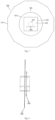
- the imaging system for radiographic inspection includes an inspection area 100, a first ray source assembly 200, and a first detector assembly 300.
- the first ray source assembly 200 is used to emit X-rays.
- the first detector assembly 300 is used to receive X-rays emitted from the first ray source assembly 200 and transmitted through the inspection area 100 of the imaging system.
- the first ray source assembly 200 and the first detector assembly 300 are arranged to surround the inspection area 100, that is, located radially outside of the inspection area 100.
- the imaging system is configured such that the first ray source assembly 200 and the first detector assembly 300 can move relative to an object under inspection in a travelling direction.
- the imaging system defines the inspection area 100.
- "inspection area” refers to an area that the object under inspection can enter.
- the inspection area 100 includes a first end and a second end.
- the object under inspection is transferred into the inspection area 100 from one of the first end and the second end, and leaves the inspection area 100 from the other one.
- the imaging system further includes a carrying device 400 for carrying the object under inspection.
- the first ray source assembly 200 and the first detector assembly 300 can move relative to the carrying device 400 in the travelling direction.
- the region of interest of the object under inspection can enter the imaging area 110 of the inspection area 100.
- the carrying device 400 is used to transfer the object under inspection in the travelling direction to enter the inspection area 100.
- the travelling direction is parallel to a horizontal direction.
- the carrying device 400 can transfer the object under inspection back and forth in the travelling direction through the inspection area 100, that is, transfer the object under inspection back and forth in opposite directions.
- an axial direction refers to a direction parallel to the travelling direction
- a radial direction refers to a direction radiating outward from the central axis in a plane perpendicular to the travelling direction
- a circumferential direction refers to a direction perpendicular to the "radial direction” in a plane perpendicular to the travelling direction.
- the plurality of distributed ray sources 210 of the first ray source assembly 200 have a combined extension angle of greater than 180 degrees around the imaging area 110 relative to the central axis, when viewed in the travelling direction.
- the extension angle of each distributed ray source 210 around the imaging area 110 relative to the central axis represents the angle range of all the first target spots of the corresponding distributed ray source 210 relative to the imaging area 110 (relative to the central axis of the imaging area 110).
- the first ray source assembly 200 includes a plurality of distributed ray sources 210, the plurality of distributed ray sources 210 at different scanning positions relative to the imaging area 110 can provide a combined extension angle.
- the first detector assembly 300 is used to receive X-rays that emitted from the first ray source assembly 200 and transmit through the imaging area 110 of the imaging system.
- the plurality of first detector units 310 are arranged in the same plane (hereinafter referred to as "a detector plane").
- “detector units are arranged in the same plane” means that center planes of the detector units (such as center planes of the detector crystals) are all arranged in the same plane.
- the center planes of the plurality of first detector units 310 are arranged in the same plane by the same positioning reference.
- the detector plane is substantially perpendicular to the travelling direction (the central axis).
- the first detector unit 310 includes a single row of detector crystals or multiple rows of detector crystals.
- the plurality of first detector units 310 form a complete detector ring.
- the detector ring formed by the plurality of first detector units 310 may be incomplete, that is, may include a gap.
- the plurality of first detector units 310 are divided into multiple segments, and the first detector units 310 of different segments can be spaced apart from each other around the imaging area.
- the ray emission range of each of these first target spots of the first ray source assembly 200 is selected such that it is insufficient to cover the inspection area 100, that is, the ray emission range of each of these first target spots is smaller than the inspection area 100.
- the ray emission range of each first target spot of the first ray source assembly 200 can cover the imaging area 110, and optionally, the ray emission range of each first target spot is insufficient to cover the inspection area 100.
- the first ray source assembly can provide a smaller ray emission range to merely cover the imaging area, so that transmission imaging can be performed only on the imaging area and the region of interest of the object under inspection.
- the imaging area 110 is defined between the first ray source plane of the first ray source assembly 200 and an outer edge of the first detector assembly 300 away from the first ray source assembly 200.
- the imaging area 110 is defined as a cylindrical area.
- the central axis of the imaging area 110 is the rotation axis of the cylindrical area.
- the imaging area 110 is defined to be sufficient to accommodate the region of interest of the object under inspection.
- the imaging system is configured such that each point in the imaging area 110 can be penetrated by the X-rays from the first ray source assembly 200 and that the X-rays after penetrating the corresponding point can be detected by the first detector assembly 300.
- Fig. 4 is a partial sectional view of an imaging system according to some embodiments of the present disclosure.
- the first deflection angle is set such that the X-rays emitted by each distributed ray source 210 of the first ray source assembly 200 will not be blocked by the first detector assembly 300 before passing through the imaging area. In some embodiments, when the ray emission direction of the first ray source assembly 200 is deflected relative to the first detector assembly 300, the ray emission direction is not perpendicular to the central axis of the imaging area.
- the X-rays emitted by the distributed ray source 210 of the first ray source assembly 200 can avoid the detector units 310 of the first detector assembly 300 on the same side, and also can be received by the detector units 310 of the first detector assembly 200 on other sides.
- the carrying device 400 when viewed along the central axis (or the travelling direction), is arranged to be located at the radial inner side of the first detector assembly 300, and the first detector assembly 300 is arranged to be located at the radial inner side of the first ray source assembly 200.
- the first ray source assembly 200, the first detector assembly 300 and the carrying device 400 are arranged sequentially from outside to inside.
- the ray source control device is configured such that the first ray source assembly 200 simultaneously emit X-rays from at least two first target spots to the imaging area 110 each time the first ray source assembly 200 is controlled to emit X-rays.
- each X-ray emission of the first ray source assembly 200 is simultaneous X-ray emission from multiple target spots.
- the ray emission range of each first target spot can cover the imaging area 110, and the detector crystals of the first detector assembly 300 corresponding to the ray emission ranges of any two first target spots do not coincide with each other.
- the imaging system can perform transmission imaging only on the imaging area 110 and the region of interest of the object under inspection located therein, thereby reducing the occupied volume and cost of the imaging system.
- the first ray source assembly 200 can simultaneously emit X-rays from six first target spots.
- the ray emission mode of the first ray source assembly 200 of the imaging system is described below.
- the first ray source assembly 200 includes a total of N first target spots, and all the N first target spots are divided into M groups, with M ⁇ N/2.
- Each group includes the same or different number of first target spots, and each group includes at least one first target spot (that is, the number of first target spots in each group can be one).
- the first target spots in each group come from different distributed ray sources 210 respectively.
- the first target spots in each group do not coincide with each other (that is, each first target spot belongs to only one group).
- the detector crystals of the first detector assembly 300 corresponding to the ray emission ranges of the respective first target spots do not coincide with each other.
- the ray source control device controls all the first target spots in one group to simultaneously emit X-rays, and makes the M groups of first target spots to emit X-rays in turn.
- the imaging system can further be configured to reconstruct a three-dimensional scanning (CT) image of the region of interest of the object under inspection based on the detection data of the first detector assembly 300.
- CT three-dimensional scanning
- the imaging system can adopt iterative reconstruction algorithm, analytical reconstruction algorithm, or the like, or a combination of different reconstruction algorithms, when reconstructing the three-dimensional scanning image of the region of interest of the object under inspection.
- the projection data may be truncated, and in this case, the imaging of the region of interest of the object under inspection belongs to an internal problem of CT. Compared with the image reconstruction when the entire object under inspection is covered by the ray emission range, there is a problem that the solution of the CT internal problem is not unique in theory.
- the first ray source assembly 200 can further include a second target spot (also called a target spot with large fan angle), of which the ray emission range can cover the inspection area 100.
- the first ray source assembly 200 further includes at least one second target spot (the target spot with large fan angle).
- the ray emission range of the second target spot is selected to be able to cover the inspection area 100.
- the first detector assembly 300 is further configured to receive X-rays emitted from the second target spot of the first ray source assembly 200 and transmitted through the inspection area 100.
- the distributed ray source 210 including both the first target spot and the second target spot can arrange each target spot in the same way as the distributed ray source 210 including only the first target spot.
- the ray source control device is configured such that the second target spot does not emit X-rays when the first target spot of the first ray source assembly 200 emits X-rays, and that the first target spot does not emit X-rays when the second target spot of the first ray source assembly 200 emits X-rays. Therefore, the target spot with large fan angle and the target spot with small fan angle of the imaging system emit X-rays separately.
- the first ray source assembly 200 includes a plurality of second target spots.
- the ray source control device is configured such that the first ray source assembly 200 simultaneously emits X-rays from at least two second target spots to the inspection area.
- the first detector crystals corresponding to the ray emission ranges of any two second target spots do not coincide with each other. Therefore, the first ray source assembly 200 can include more than two second target spots simultaneously emitting X-rays.
- a plurality of second target spots of the first ray source assembly 200 are uniformly distributed.
- the first ray source assembly 200 includes a total of 9 target spots, wherein the first, fourth, and seventh target spots can be the second target spots, and the remaining second, third, fifth, sixth, eighth, and ninth target spots can be the first target spots as described above.
- the first ray source assembly 200 includes N1 first target spots and N2 second target spots.
- the ray source control device can divide N1 first target spots into M groups (M ⁇ N1/2) by referring to any ray emission mode as described above, and control the M groups of first target spots and the N2 second target spots to emit X-rays in a predetermined sequence.
- the ray source control device is configured such that the second target spots do not emit X-rays when the first target spots of the first ray source assembly 200 emit X-rays, and that the first target spots do not emit X-rays when the second target spots of the first ray source assembly 200 emit X-rays.
- the detector crystals of the first detector assembly 300 corresponding to the ray emission ranges of the respective first target spots do not coincide with each other.
- the first detector crystals corresponding to the ray emission ranges of the second target spots that simultaneously emits X-rays do not coincide with each other.
- the target spots with large fan angle can be used to image the entire object under inspection, which is helpful to avoid or solve the internal problem of CT; meanwhile, the target spots with small fan angle can be used to improve the imaging quality of the region of interest.
- each second detector unit 610 includes a plurality of second detector crystals.
- the second detector crystals 611 of each second detector unit 610 are arranged side by side with the first detector crystals 311 of the corresponding first detector unit 310.
- "arranged side by side” means that the corresponding first detector crystals and the second detector crystals are in roughly the same radial and circumferential positions when viewed in the travelling direction.
- the corresponding second detector crystals 611 and the first detector crystals 311 are arranged to contact or be spaced apart from each other, which will be described in detail below with reference to the accompanying drawings.
- Fig. 5 is a schematic diagram of a first detector assembly and a second detector assembly according to some embodiments of the present disclosure.
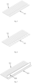
- Fig. 6 is a schematic diagram of a first detector assembly and a second detector assembly according to some embodiments of the present disclosure. As shown in Figs. 5 and 6 , the second detector crystals 611 of the second detector unit are spaced apart from the first detector crystals 311 of the corresponding first detector unit along the travelling direction (or the central axis).
- the second detector crystals of each second detector unit 610 and the first detector crystals of the corresponding first detector unit 310 are arranged to contact each other along the travelling direction (or the central axis).
- the imaging system further includes a blocking member arranged such that the second detector unit 610 does not receive the main X-rays emitted from the first ray source assembly 200. Because the second detector crystals are arranged immediately adjacent to the first detector crystals, and thus may receive some of the main X-rays. By providing the blocking member, the second detector unit 610 can be prevented from receiving the main X-rays, so as to improve the detection accuracy of the second detector assembly and the detection accuracy of the corrected transmission X-ray signals.
- the blocking member 620 can be arranged farther away from the second detector unit 610 and the first detector unit 310 (as shown in Fig. 9 ), or closer to the second detector unit 610 and the first detector unit 310 (as shown in Fig. 10 ).
- the blocking member 620 is a horizontal blocking member, that is, it extends substantially in the horizontal direction when viewed in the circumferential direction.
- the number of second detector crystals 611 of each second detector unit is equal to the number of first detector crystals 311 of the corresponding first detector unit.
- one column (at least one) of second detector crystals 611 for receiving the scattered signals are correspondingly provided.
- the scatter correction mode is exemplarily described below. Assuming that the readings of the respective columns of first detector crystals 311 of the first detector unit 310 are pl, p2, p3... respectively, and the readings of the respective columns of second detector crystals 611 in of the second detector unit 610 are q, and considering that the scattered signal is a low-frequency signal and the width of the detection crystal is small, the transmission X-ray signals after the scatter correction can be expressed as p1-q, p2-q, p3-q.
- Each third target spot of the second ray source assembly 700 has a ray emission range.
- the ray emission ranges of at least some of the third target spots of the second ray source assembly 700 are selected to be able to cover the imaging area 110.
- the ray emission range of each of these third target spots of the second ray source assembly 700 is selected to be insufficient to cover the inspection area 100, that is, the ray emission range of each of these third target spots is smaller than the inspection area 100.
- the ray emission range of each third target spot of the second ray source assembly 700 can cover the imaging area 110, and optionally, the ray emission range of each third target spot is insufficient to cover the inspection area 100.
- the first ray source assembly 200 and the second ray source assembly 700 are respectively arranged on two sides of the first detector assembly 300, the X-rays emitted by the first ray source assembly 200 and the X-rays emitted by the second ray source assembly 700 deflect opposite each other.
- the first deflection angle is equal to the second deflection angle.
- the detector crystal of the first detector assembly 300 corresponding to the ray emission range of the first target spot of the first ray source assembly 200 and the detector crystal of the first detector assembly 300 corresponding to the ray emission range of the third target spot of the second ray source assembly 700 do not coincide with each other.
- the imaging method can further adjust the position of the region of interest of the object under inspection relative to the imaging area 110 through the position adjustment function of the imaging system. For example, when the region of interest of the object under inspection is not completely located in the imaging area 110, the region of interest of the object under inspection can be moved to be completely located in the imaging area 110 by means of the position adjustment function of the imaging system.
Landscapes
- Health & Medical Sciences (AREA)
- Engineering & Computer Science (AREA)
- Life Sciences & Earth Sciences (AREA)
- Medical Informatics (AREA)
- Physics & Mathematics (AREA)
- General Health & Medical Sciences (AREA)
- Nuclear Medicine, Radiotherapy & Molecular Imaging (AREA)
- Radiology & Medical Imaging (AREA)
- Pathology (AREA)
- Public Health (AREA)
- Heart & Thoracic Surgery (AREA)
- Veterinary Medicine (AREA)
- Animal Behavior & Ethology (AREA)
- Surgery (AREA)
- Optics & Photonics (AREA)
- Biophysics (AREA)
- High Energy & Nuclear Physics (AREA)
- Biomedical Technology (AREA)
- Molecular Biology (AREA)
- Theoretical Computer Science (AREA)
- Pulmonology (AREA)
- General Physics & Mathematics (AREA)
- Multimedia (AREA)
- Quality & Reliability (AREA)
- Computer Vision & Pattern Recognition (AREA)
- Biochemistry (AREA)
- Immunology (AREA)
- Analytical Chemistry (AREA)
- Chemical & Material Sciences (AREA)
- Analysing Materials By The Use Of Radiation (AREA)
- Apparatus For Radiation Diagnosis (AREA)
Applications Claiming Priority (2)
| Application Number | Priority Date | Filing Date | Title |
|---|---|---|---|
| CN202111204463.6A CN115105110B (zh) | 2021-10-15 | 2021-10-15 | 用于射线检查的成像系统和方法 |
| PCT/CN2022/124449 WO2023061340A1 (fr) | 2021-10-15 | 2022-10-10 | Système d'imagerie et procédé d'examen radiographique |
Publications (3)
| Publication Number | Publication Date |
|---|---|
| EP4393406A1 true EP4393406A1 (fr) | 2024-07-03 |
| EP4393406A4 EP4393406A4 (fr) | 2025-01-08 |
| EP4393406B1 EP4393406B1 (fr) | 2025-09-24 |
Family
ID=83325430
Family Applications (1)
| Application Number | Title | Priority Date | Filing Date |
|---|---|---|---|
| EP22880277.3A Active EP4393406B1 (fr) | 2021-10-15 | 2022-10-10 | Système d'imagerie et procédé d'inspection radiographique |
Country Status (6)
| Country | Link |
|---|---|
| US (1) | US12437397B2 (fr) |
| EP (1) | EP4393406B1 (fr) |
| CN (2) | CN119184720B (fr) |
| ES (1) | ES3057526T3 (fr) |
| PL (1) | PL4393406T3 (fr) |
| WO (1) | WO2023061340A1 (fr) |
Families Citing this family (7)
| Publication number | Priority date | Publication date | Assignee | Title |
|---|---|---|---|---|
| CN119184720B (zh) | 2021-10-15 | 2025-09-30 | 清华大学 | 用于射线检查的成像系统和方法 |
| CN116602701A (zh) * | 2023-04-17 | 2023-08-18 | 清华大学 | 一种基于分布式光源和分布式探测器的五合一成像设备 |
| CN116297569B (zh) * | 2023-04-28 | 2023-09-05 | 杭州睿影科技有限公司 | 一种基于x射线的物体检测方法、系统及处理设备 |
| CN118216940B (zh) * | 2024-03-20 | 2025-04-18 | 清华大学 | 分布式射线源ct成像系统及成像方法 |
| CN119224018B (zh) * | 2024-12-04 | 2025-02-28 | 清华大学 | Ct成像系统 |
| CN119224019B (zh) * | 2024-12-04 | 2025-03-07 | 清华大学 | Ct成像系统的成像方法 |
| CN120253905A (zh) * | 2025-06-04 | 2025-07-04 | 赣州好朋友科技股份有限公司 | 一种拼接环形x射线成像系统及智能选矿机 |
Family Cites Families (27)
| Publication number | Priority date | Publication date | Assignee | Title |
|---|---|---|---|---|
| US4442489A (en) * | 1979-06-16 | 1984-04-10 | U.S. Philips Corporation | Device for computed tomography |
| US6385278B1 (en) * | 2000-04-28 | 2002-05-07 | Ge Medical Systems Global Technology Company, Llc | Method and apparatus for region of interest multislice CT scan |
| US6876724B2 (en) * | 2000-10-06 | 2005-04-05 | The University Of North Carolina - Chapel Hill | Large-area individually addressable multi-beam x-ray system and method of forming same |
| WO2002065917A1 (fr) * | 2001-02-23 | 2002-08-29 | Mitsubishi Heavy Industries, Ltd. | Appareil ct a rayons x |
| US6661866B1 (en) | 2002-08-28 | 2003-12-09 | Ge Medical Systems Global Technology Company, Llc | Integrated CT-PET system |
| JP4314008B2 (ja) * | 2002-10-01 | 2009-08-12 | 株式会社東芝 | X線ctスキャナ |
| JP4545144B2 (ja) * | 2003-03-13 | 2010-09-15 | コーニンクレッカ フィリップス エレクトロニクス エヌ ヴィ | コンピュータ制御のトモグラフィック画像システム |
| CN101472524B (zh) * | 2006-06-22 | 2011-05-25 | 皇家飞利浦电子股份有限公司 | 多管成像系统散射校正 |
| CN101561405B (zh) * | 2008-04-17 | 2011-07-06 | 清华大学 | 一种直线轨迹扫描成像系统和方法 |
| KR101373006B1 (ko) * | 2011-12-27 | 2014-03-13 | 삼성전자주식회사 | 엑스레이 조사 범위를 조절하는 방법 및 장치 |
| CN102764137B (zh) * | 2012-07-27 | 2014-06-04 | 苏州生物医学工程技术研究所 | 一种静态ct扫描仪及其散射x光子校正方法 |
| JP2014226376A (ja) * | 2013-05-23 | 2014-12-08 | 株式会社東芝 | X線ct装置 |
| PL228457B1 (pl) * | 2013-08-30 | 2018-03-30 | Univ Jagiellonski | Tomograf hybrydowy TOF-PET/CT |
| CN104470178A (zh) * | 2013-09-18 | 2015-03-25 | 清华大学 | X射线装置以及具有该x射线装置的ct设备 |
| CN104374783B (zh) * | 2013-12-26 | 2017-06-16 | 清华大学 | Ct系统及其方法 |
| CN104749648A (zh) * | 2013-12-27 | 2015-07-01 | 清华大学 | 多能谱静态ct设备 |
| CN104897703B (zh) * | 2014-03-04 | 2018-09-28 | 清华大学 | 检查设备、方法和系统 |
| CN104101910A (zh) | 2014-07-04 | 2014-10-15 | 清华大学 | 基于分布式辐射源的x射线背散射通道式车辆安检系统和方法 |
| CN105374654B (zh) * | 2014-08-25 | 2018-11-06 | 同方威视技术股份有限公司 | 电子源、x射线源、使用了该x射线源的设备 |
| CN104483711B (zh) * | 2014-12-17 | 2020-02-21 | 同方威视技术股份有限公司 | 基于分布式光源的辐射成像系统 |
| CN106783484B (zh) * | 2016-12-15 | 2018-10-16 | 清华大学 | 光阴极分布式x射线发生装置及具有该装置的ct设备 |
| CN107464734B (zh) * | 2017-09-18 | 2024-04-26 | 同方威视技术股份有限公司 | 分布式x射线光源及其控制方法和ct设备 |
| DE102019107348A1 (de) * | 2018-03-22 | 2019-09-26 | Werth Messtechnik Gmbh | Vorrichtung und Verfahren zur computertomografischen Messung von Werkstücken |
| CN211381407U (zh) * | 2019-09-12 | 2020-09-01 | 北京纳米维景科技有限公司 | 具有成对射线源环的静态实时ct成像系统 |
| US11058369B2 (en) * | 2019-11-15 | 2021-07-13 | GE Precision Healthcare LLC | Systems and methods for coherent scatter imaging using a segmented photon-counting detector for computed tomography |
| CN111759335B (zh) * | 2020-05-29 | 2023-05-02 | 东软医疗系统股份有限公司 | 多能谱成像数据的获取方法、装置、电子设备、存储介质 |
| CN119184720B (zh) * | 2021-10-15 | 2025-09-30 | 清华大学 | 用于射线检查的成像系统和方法 |
-
2021
- 2021-10-15 CN CN202411318154.5A patent/CN119184720B/zh active Active
- 2021-10-15 CN CN202111204463.6A patent/CN115105110B/zh active Active
-
2022
- 2022-10-10 PL PL22880277.3T patent/PL4393406T3/pl unknown
- 2022-10-10 WO PCT/CN2022/124449 patent/WO2023061340A1/fr not_active Ceased
- 2022-10-10 ES ES22880277T patent/ES3057526T3/es active Active
- 2022-10-10 EP EP22880277.3A patent/EP4393406B1/fr active Active
- 2022-10-17 US US17/967,039 patent/US12437397B2/en active Active
Also Published As
| Publication number | Publication date |
|---|---|
| US12437397B2 (en) | 2025-10-07 |
| EP4393406A4 (fr) | 2025-01-08 |
| PL4393406T3 (pl) | 2026-02-23 |
| CN115105110A (zh) | 2022-09-27 |
| EP4393406B1 (fr) | 2025-09-24 |
| CN119184720B (zh) | 2025-09-30 |
| CN119184720A (zh) | 2024-12-27 |
| ES3057526T3 (en) | 2026-03-03 |
| US20230124325A1 (en) | 2023-04-20 |
| CN115105110B (zh) | 2024-11-08 |
| WO2023061340A1 (fr) | 2023-04-20 |
Similar Documents
| Publication | Publication Date | Title |
|---|---|---|
| EP4393406A1 (fr) | Système d'imagerie et procédé d'examen radiographique | |
| US6956925B1 (en) | Methods and systems for multi-modality imaging | |
| CN114947911B (zh) | 用于射线检查的成像系统 | |
| EP2963455B1 (fr) | Système d'inspection de sécurité à rétrodiffusion de rayons x ayant une source de rayons x distribuée et procédé utilisant celui-ci | |
| EP4369058A1 (fr) | Système et procédé d'inspection | |
| US8530849B2 (en) | Electron beam scanner | |
| US20050226363A1 (en) | Stationary computed tomography system and method | |
| US20050135550A1 (en) | Method and apparatus for employing multiple axial-sources | |
| EP4628879A1 (fr) | Système et procédé de tomodensitométrie | |
| US12510497B2 (en) | Inspection system and method | |
| CN115097535A (zh) | 检查系统和方法 | |
| US6792077B2 (en) | Collimation system for dual slice EBT scanner | |
| US10541061B2 (en) | System for generating and collimating an X-ray beam | |
| US12571936B2 (en) | Inspection system and inspection method | |
| US7688939B2 (en) | Object rotation for CT data acquisition | |
| CN219915424U (zh) | Ct扫描系统 | |
| US20240418901A1 (en) | Static or quasi-static multi-view or 3d inspection of cargo | |
| US8625738B2 (en) | Radiation therapy and scanning system | |
| HK40101144A (en) | Imaging system for radiographic examination | |
| CN119534497B (zh) | Ct成像系统 | |
| CN119224018A (zh) | Ct成像系统 |
Legal Events
| Date | Code | Title | Description |
|---|---|---|---|
| STAA | Information on the status of an ep patent application or granted ep patent |
Free format text: STATUS: THE INTERNATIONAL PUBLICATION HAS BEEN MADE |
|
| PUAI | Public reference made under article 153(3) epc to a published international application that has entered the european phase |
Free format text: ORIGINAL CODE: 0009012 |
|
| STAA | Information on the status of an ep patent application or granted ep patent |
Free format text: STATUS: REQUEST FOR EXAMINATION WAS MADE |
|
| 17P | Request for examination filed |
Effective date: 20240327 |
|
| AK | Designated contracting states |
Kind code of ref document: A1 Designated state(s): AL AT BE BG CH CY CZ DE DK EE ES FI FR GB GR HR HU IE IS IT LI LT LU LV MC ME MK MT NL NO PL PT RO RS SE SI SK SM TR |
|
| A4 | Supplementary search report drawn up and despatched |
Effective date: 20241206 |
|
| RIC1 | Information provided on ipc code assigned before grant |
Ipc: A61B 6/03 20060101AFI20241202BHEP |
|
| DAV | Request for validation of the european patent (deleted) | ||
| DAX | Request for extension of the european patent (deleted) | ||
| GRAP | Despatch of communication of intention to grant a patent |
Free format text: ORIGINAL CODE: EPIDOSNIGR1 |
|
| STAA | Information on the status of an ep patent application or granted ep patent |
Free format text: STATUS: GRANT OF PATENT IS INTENDED |
|
| INTG | Intention to grant announced |
Effective date: 20250701 |
|
| GRAS | Grant fee paid |
Free format text: ORIGINAL CODE: EPIDOSNIGR3 |
|
| GRAA | (expected) grant |
Free format text: ORIGINAL CODE: 0009210 |
|
| STAA | Information on the status of an ep patent application or granted ep patent |
Free format text: STATUS: THE PATENT HAS BEEN GRANTED |
|
| AK | Designated contracting states |
Kind code of ref document: B1 Designated state(s): AL AT BE BG CH CY CZ DE DK EE ES FI FR GB GR HR HU IE IS IT LI LT LU LV MC ME MK MT NL NO PL PT RO RS SE SI SK SM TR |
|
| REG | Reference to a national code |
Ref country code: GB Ref legal event code: FG4D |
|
| REG | Reference to a national code |
Ref country code: CH Ref legal event code: EP |
|
| REG | Reference to a national code |
Ref country code: DE Ref legal event code: R096 Ref document number: 602022022093 Country of ref document: DE |
|
| REG | Reference to a national code |
Ref country code: IE Ref legal event code: FG4D |
|
| REG | Reference to a national code |
Ref country code: SE Ref legal event code: TRGR |
|
| REG | Reference to a national code |
Ref country code: CH Ref legal event code: U11 Free format text: ST27 STATUS EVENT CODE: U-0-0-U10-U11 (AS PROVIDED BY THE NATIONAL OFFICE) Effective date: 20251230 |
|
| PG25 | Lapsed in a contracting state [announced via postgrant information from national office to epo] |
Ref country code: NO Free format text: LAPSE BECAUSE OF FAILURE TO SUBMIT A TRANSLATION OF THE DESCRIPTION OR TO PAY THE FEE WITHIN THE PRESCRIBED TIME-LIMIT Effective date: 20251224 |
|
| REG | Reference to a national code |
Ref country code: LT Ref legal event code: MG9D |
|
| PGFP | Annual fee paid to national office [announced via postgrant information from national office to epo] |
Ref country code: AT Payment date: 20260113 Year of fee payment: 4 |
|
| PG25 | Lapsed in a contracting state [announced via postgrant information from national office to epo] |
Ref country code: FI Free format text: LAPSE BECAUSE OF FAILURE TO SUBMIT A TRANSLATION OF THE DESCRIPTION OR TO PAY THE FEE WITHIN THE PRESCRIBED TIME-LIMIT Effective date: 20250924 |
|
| PG25 | Lapsed in a contracting state [announced via postgrant information from national office to epo] |
Ref country code: HR Free format text: LAPSE BECAUSE OF FAILURE TO SUBMIT A TRANSLATION OF THE DESCRIPTION OR TO PAY THE FEE WITHIN THE PRESCRIBED TIME-LIMIT Effective date: 20250924 |
|
| PGFP | Annual fee paid to national office [announced via postgrant information from national office to epo] |
Ref country code: FR Payment date: 20251117 Year of fee payment: 4 |
|
| PG25 | Lapsed in a contracting state [announced via postgrant information from national office to epo] |
Ref country code: GR Free format text: LAPSE BECAUSE OF FAILURE TO SUBMIT A TRANSLATION OF THE DESCRIPTION OR TO PAY THE FEE WITHIN THE PRESCRIBED TIME-LIMIT Effective date: 20251225 |
|
| PGFP | Annual fee paid to national office [announced via postgrant information from national office to epo] |
Ref country code: SE Payment date: 20251118 Year of fee payment: 4 Ref country code: CH Payment date: 20251230 Year of fee payment: 4 |
|
| PG25 | Lapsed in a contracting state [announced via postgrant information from national office to epo] |
Ref country code: LV Free format text: LAPSE BECAUSE OF FAILURE TO SUBMIT A TRANSLATION OF THE DESCRIPTION OR TO PAY THE FEE WITHIN THE PRESCRIBED TIME-LIMIT Effective date: 20250924 |
|
| PG25 | Lapsed in a contracting state [announced via postgrant information from national office to epo] |
Ref country code: BG Free format text: LAPSE BECAUSE OF FAILURE TO SUBMIT A TRANSLATION OF THE DESCRIPTION OR TO PAY THE FEE WITHIN THE PRESCRIBED TIME-LIMIT Effective date: 20250924 |
|
| PG25 | Lapsed in a contracting state [announced via postgrant information from national office to epo] |
Ref country code: RS Free format text: LAPSE BECAUSE OF FAILURE TO SUBMIT A TRANSLATION OF THE DESCRIPTION OR TO PAY THE FEE WITHIN THE PRESCRIBED TIME-LIMIT Effective date: 20251224 |
|
| REG | Reference to a national code |
Ref country code: NL Ref legal event code: MP Effective date: 20250924 |
|
| PGFP | Annual fee paid to national office [announced via postgrant information from national office to epo] |
Ref country code: ES Payment date: 20251212 Year of fee payment: 4 |
|
| PG25 | Lapsed in a contracting state [announced via postgrant information from national office to epo] |
Ref country code: NL Free format text: LAPSE BECAUSE OF FAILURE TO SUBMIT A TRANSLATION OF THE DESCRIPTION OR TO PAY THE FEE WITHIN THE PRESCRIBED TIME-LIMIT Effective date: 20250924 |
|
| REG | Reference to a national code |
Ref country code: CH Ref legal event code: R17 Free format text: ST27 STATUS EVENT CODE: U-0-0-R10-R17 (AS PROVIDED BY THE NATIONAL OFFICE) Effective date: 20260218 |
|
| REG | Reference to a national code |
Ref country code: ES Ref legal event code: FG2A Ref document number: 3057526 Country of ref document: ES Kind code of ref document: T3 Effective date: 20260303 |
|
| REG | Reference to a national code |
Ref country code: AT Ref legal event code: MK05 Ref document number: 1839755 Country of ref document: AT Kind code of ref document: T Effective date: 20250924 |
|
| PG25 | Lapsed in a contracting state [announced via postgrant information from national office to epo] |
Ref country code: SM Free format text: LAPSE BECAUSE OF FAILURE TO SUBMIT A TRANSLATION OF THE DESCRIPTION OR TO PAY THE FEE WITHIN THE PRESCRIBED TIME-LIMIT Effective date: 20250924 |
|
| PGFP | Annual fee paid to national office [announced via postgrant information from national office to epo] |
Ref country code: DE Payment date: 20251223 Year of fee payment: 4 |
|
| PG25 | Lapsed in a contracting state [announced via postgrant information from national office to epo] |
Ref country code: AT Free format text: LAPSE BECAUSE OF FAILURE TO SUBMIT A TRANSLATION OF THE DESCRIPTION OR TO PAY THE FEE WITHIN THE PRESCRIBED TIME-LIMIT Effective date: 20250924 |
|
| PG25 | Lapsed in a contracting state [announced via postgrant information from national office to epo] |
Ref country code: RO Free format text: LAPSE BECAUSE OF FAILURE TO SUBMIT A TRANSLATION OF THE DESCRIPTION OR TO PAY THE FEE WITHIN THE PRESCRIBED TIME-LIMIT Effective date: 20250924 Ref country code: IT Free format text: LAPSE BECAUSE OF FAILURE TO SUBMIT A TRANSLATION OF THE DESCRIPTION OR TO PAY THE FEE WITHIN THE PRESCRIBED TIME-LIMIT Effective date: 20250924 |
|
| PG25 | Lapsed in a contracting state [announced via postgrant information from national office to epo] |
Ref country code: IS Free format text: LAPSE BECAUSE OF FAILURE TO SUBMIT A TRANSLATION OF THE DESCRIPTION OR TO PAY THE FEE WITHIN THE PRESCRIBED TIME-LIMIT Effective date: 20260124 |
|
| PG25 | Lapsed in a contracting state [announced via postgrant information from national office to epo] |
Ref country code: CZ Free format text: LAPSE BECAUSE OF FAILURE TO SUBMIT A TRANSLATION OF THE DESCRIPTION OR TO PAY THE FEE WITHIN THE PRESCRIBED TIME-LIMIT Effective date: 20250924 Ref country code: PT Free format text: LAPSE BECAUSE OF FAILURE TO SUBMIT A TRANSLATION OF THE DESCRIPTION OR TO PAY THE FEE WITHIN THE PRESCRIBED TIME-LIMIT Effective date: 20260126 |
|
| PGFP | Annual fee paid to national office [announced via postgrant information from national office to epo] |
Ref country code: PL Payment date: 20251119 Year of fee payment: 4 |
|
| PG25 | Lapsed in a contracting state [announced via postgrant information from national office to epo] |
Ref country code: EE Free format text: LAPSE BECAUSE OF FAILURE TO SUBMIT A TRANSLATION OF THE DESCRIPTION OR TO PAY THE FEE WITHIN THE PRESCRIBED TIME-LIMIT Effective date: 20250924 Ref country code: SK Free format text: LAPSE BECAUSE OF FAILURE TO SUBMIT A TRANSLATION OF THE DESCRIPTION OR TO PAY THE FEE WITHIN THE PRESCRIBED TIME-LIMIT Effective date: 20250924 |