EP4393653A2 - Robotische chirurgische anordnung - Google Patents
Robotische chirurgische anordnung Download PDFInfo
- Publication number
- EP4393653A2 EP4393653A2 EP24176173.3A EP24176173A EP4393653A2 EP 4393653 A2 EP4393653 A2 EP 4393653A2 EP 24176173 A EP24176173 A EP 24176173A EP 4393653 A2 EP4393653 A2 EP 4393653A2
- Authority
- EP
- European Patent Office
- Prior art keywords
- tendon
- micro
- positioning
- movement
- arm
- Prior art date
- Legal status (The legal status is an assumption and is not a legal conclusion. Google has not performed a legal analysis and makes no representation as to the accuracy of the status listed.)
- Pending
Links
Images


Classifications
-
- A—HUMAN NECESSITIES
- A61—MEDICAL OR VETERINARY SCIENCE; HYGIENE
- A61B—DIAGNOSIS; SURGERY; IDENTIFICATION
- A61B34/00—Computer-aided surgery; Manipulators or robots specially adapted for use in surgery
- A61B34/30—Surgical robots
- A61B34/35—Surgical robots for telesurgery
-
- A—HUMAN NECESSITIES
- A61—MEDICAL OR VETERINARY SCIENCE; HYGIENE
- A61B—DIAGNOSIS; SURGERY; IDENTIFICATION
- A61B1/00—Instruments for performing medical examinations of the interior of cavities or tubes of the body by visual or photographical inspection, e.g. endoscopes; Illuminating arrangements therefor
- A61B1/313—Instruments for performing medical examinations of the interior of cavities or tubes of the body by visual or photographical inspection, e.g. endoscopes; Illuminating arrangements therefor for introducing through surgical openings, e.g. laparoscopes
- A61B1/3132—Instruments for performing medical examinations of the interior of cavities or tubes of the body by visual or photographical inspection, e.g. endoscopes; Illuminating arrangements therefor for introducing through surgical openings, e.g. laparoscopes for laparoscopy
-
- A—HUMAN NECESSITIES
- A61—MEDICAL OR VETERINARY SCIENCE; HYGIENE
- A61B—DIAGNOSIS; SURGERY; IDENTIFICATION
- A61B10/00—Instruments for taking body samples for diagnostic purposes; Other methods or instruments for diagnosis, e.g. for vaccination diagnosis, sex determination or ovulation-period determination; Throat striking implements
- A61B10/02—Instruments for taking cell samples or for biopsy
- A61B10/04—Endoscopic instruments, e.g. catheter-type instruments
-
- A—HUMAN NECESSITIES
- A61—MEDICAL OR VETERINARY SCIENCE; HYGIENE
- A61B—DIAGNOSIS; SURGERY; IDENTIFICATION
- A61B17/00—Surgical instruments, devices or methods
- A61B17/00234—Surgical instruments, devices or methods for minimally invasive surgery
-
- A—HUMAN NECESSITIES
- A61—MEDICAL OR VETERINARY SCIENCE; HYGIENE
- A61B—DIAGNOSIS; SURGERY; IDENTIFICATION
- A61B17/00—Surgical instruments, devices or methods
- A61B17/04—Surgical instruments, devices or methods for suturing wounds; Holders or packages for needles or suture materials
- A61B17/06—Needles ; Sutures; Needle-suture combinations; Holders or packages for needles or suture materials
- A61B17/062—Needle manipulators
-
- A—HUMAN NECESSITIES
- A61—MEDICAL OR VETERINARY SCIENCE; HYGIENE
- A61B—DIAGNOSIS; SURGERY; IDENTIFICATION
- A61B17/00—Surgical instruments, devices or methods
- A61B17/28—Surgical forceps
- A61B17/29—Forceps for use in minimally invasive surgery
-
- A—HUMAN NECESSITIES
- A61—MEDICAL OR VETERINARY SCIENCE; HYGIENE
- A61B—DIAGNOSIS; SURGERY; IDENTIFICATION
- A61B34/00—Computer-aided surgery; Manipulators or robots specially adapted for use in surgery
- A61B34/30—Surgical robots
-
- A—HUMAN NECESSITIES
- A61—MEDICAL OR VETERINARY SCIENCE; HYGIENE
- A61B—DIAGNOSIS; SURGERY; IDENTIFICATION
- A61B34/00—Computer-aided surgery; Manipulators or robots specially adapted for use in surgery
- A61B34/30—Surgical robots
- A61B34/37—Leader-follower robots
-
- A—HUMAN NECESSITIES
- A61—MEDICAL OR VETERINARY SCIENCE; HYGIENE
- A61B—DIAGNOSIS; SURGERY; IDENTIFICATION
- A61B34/00—Computer-aided surgery; Manipulators or robots specially adapted for use in surgery
- A61B34/70—Manipulators specially adapted for use in surgery
- A61B34/71—Manipulators operated by drive cable mechanisms
-
- A—HUMAN NECESSITIES
- A61—MEDICAL OR VETERINARY SCIENCE; HYGIENE
- A61B—DIAGNOSIS; SURGERY; IDENTIFICATION
- A61B34/00—Computer-aided surgery; Manipulators or robots specially adapted for use in surgery
- A61B34/70—Manipulators specially adapted for use in surgery
- A61B34/72—Micromanipulators
-
- A—HUMAN NECESSITIES
- A61—MEDICAL OR VETERINARY SCIENCE; HYGIENE
- A61B—DIAGNOSIS; SURGERY; IDENTIFICATION
- A61B34/00—Computer-aided surgery; Manipulators or robots specially adapted for use in surgery
- A61B34/70—Manipulators specially adapted for use in surgery
- A61B34/75—Manipulators having means for prevention or compensation of hand tremors
-
- A—HUMAN NECESSITIES
- A61—MEDICAL OR VETERINARY SCIENCE; HYGIENE
- A61B—DIAGNOSIS; SURGERY; IDENTIFICATION
- A61B90/00—Instruments, implements or accessories specially adapted for surgery or diagnosis and not covered by any of the groups A61B1/00 - A61B50/00, e.g. for luxation treatment or for protecting wound edges
- A61B90/20—Surgical microscopes characterised by non-optical aspects
- A61B90/25—Supports therefor
-
- A—HUMAN NECESSITIES
- A61—MEDICAL OR VETERINARY SCIENCE; HYGIENE
- A61B—DIAGNOSIS; SURGERY; IDENTIFICATION
- A61B90/00—Instruments, implements or accessories specially adapted for surgery or diagnosis and not covered by any of the groups A61B1/00 - A61B50/00, e.g. for luxation treatment or for protecting wound edges
- A61B90/36—Image-producing devices or illumination devices not otherwise provided for
- A61B90/361—Image-producing devices, e.g. surgical cameras
-
- A—HUMAN NECESSITIES
- A61—MEDICAL OR VETERINARY SCIENCE; HYGIENE
- A61B—DIAGNOSIS; SURGERY; IDENTIFICATION
- A61B90/00—Instruments, implements or accessories specially adapted for surgery or diagnosis and not covered by any of the groups A61B1/00 - A61B50/00, e.g. for luxation treatment or for protecting wound edges
- A61B90/40—Apparatus fixed or close to patients specially adapted for providing an aseptic surgical environment
-
- B—PERFORMING OPERATIONS; TRANSPORTING
- B23—MACHINE TOOLS; METAL-WORKING NOT OTHERWISE PROVIDED FOR
- B23H—WORKING OF METAL BY THE ACTION OF A HIGH CONCENTRATION OF ELECTRIC CURRENT ON A WORKPIECE USING AN ELECTRODE WHICH TAKES THE PLACE OF A TOOL; SUCH WORKING COMBINED WITH OTHER FORMS OF WORKING OF METAL
- B23H11/00—Auxiliary apparatus or details, not otherwise provided for
- B23H11/003—Mounting of workpieces, e.g. working-tables
-
- B—PERFORMING OPERATIONS; TRANSPORTING
- B23—MACHINE TOOLS; METAL-WORKING NOT OTHERWISE PROVIDED FOR
- B23H—WORKING OF METAL BY THE ACTION OF A HIGH CONCENTRATION OF ELECTRIC CURRENT ON A WORKPIECE USING AN ELECTRODE WHICH TAKES THE PLACE OF A TOOL; SUCH WORKING COMBINED WITH OTHER FORMS OF WORKING OF METAL
- B23H7/00—Processes or apparatus applicable to both electrical discharge machining and electrochemical machining
- B23H7/02—Wire-cutting
-
- B—PERFORMING OPERATIONS; TRANSPORTING
- B25—HAND TOOLS; PORTABLE POWER-DRIVEN TOOLS; MANIPULATORS
- B25J—MANIPULATORS; CHAMBERS PROVIDED WITH MANIPULATION DEVICES
- B25J15/00—Gripping heads and other end effectors
- B25J15/0052—Gripping heads and other end effectors multiple gripper units or multiple end effectors
-
- B—PERFORMING OPERATIONS; TRANSPORTING
- B25—HAND TOOLS; PORTABLE POWER-DRIVEN TOOLS; MANIPULATORS
- B25J—MANIPULATORS; CHAMBERS PROVIDED WITH MANIPULATION DEVICES
- B25J3/00—Manipulators of leader-follower type, i.e. both controlling unit and controlled unit perform corresponding spatial movements
- B25J3/04—Manipulators of leader-follower type, i.e. both controlling unit and controlled unit perform corresponding spatial movements involving servo mechanisms
-
- B—PERFORMING OPERATIONS; TRANSPORTING
- B25—HAND TOOLS; PORTABLE POWER-DRIVEN TOOLS; MANIPULATORS
- B25J—MANIPULATORS; CHAMBERS PROVIDED WITH MANIPULATION DEVICES
- B25J9/00—Program-controlled manipulators
- B25J9/10—Program-controlled manipulators characterised by positioning means for manipulator elements
- B25J9/1005—Program-controlled manipulators characterised by positioning means for manipulator elements comprising adjusting means
- B25J9/1015—Program-controlled manipulators characterised by positioning means for manipulator elements comprising adjusting means using additional, e.g. microadjustment of the end effector
-
- B—PERFORMING OPERATIONS; TRANSPORTING
- B25—HAND TOOLS; PORTABLE POWER-DRIVEN TOOLS; MANIPULATORS
- B25J—MANIPULATORS; CHAMBERS PROVIDED WITH MANIPULATION DEVICES
- B25J9/00—Program-controlled manipulators
- B25J9/16—Program controls
- B25J9/1656—Program controls characterised by programming, planning systems for manipulators
- B25J9/1669—Program controls characterised by programming, planning systems for manipulators characterised by special application, e.g. multi-arm co-operation, assembly, grasping
-
- B—PERFORMING OPERATIONS; TRANSPORTING
- B25—HAND TOOLS; PORTABLE POWER-DRIVEN TOOLS; MANIPULATORS
- B25J—MANIPULATORS; CHAMBERS PROVIDED WITH MANIPULATION DEVICES
- B25J9/00—Program-controlled manipulators
- B25J9/16—Program controls
- B25J9/1679—Program controls characterised by the tasks executed
- B25J9/1689—Teleoperation
-
- G—PHYSICS
- G05—CONTROLLING; REGULATING
- G05B—CONTROL OR REGULATING SYSTEMS IN GENERAL; FUNCTIONAL ELEMENTS OF SUCH SYSTEMS; MONITORING OR TESTING ARRANGEMENTS FOR SUCH SYSTEMS OR ELEMENTS
- G05B19/00—Program-control systems
- G05B19/02—Program-control systems electric
- G05B19/18—Numerical control [NC], i.e. automatically operating machines, in particular machine tools, e.g. in a manufacturing environment, so as to execute positioning, movement or co-ordinated operations by means of program data in numerical form
- G05B19/402—Numerical control [NC], i.e. automatically operating machines, in particular machine tools, e.g. in a manufacturing environment, so as to execute positioning, movement or co-ordinated operations by means of program data in numerical form characterised by control arrangements for positioning, e.g. centring a tool relative to a hole in the workpiece, additional detection means to correct position
-
- A—HUMAN NECESSITIES
- A61—MEDICAL OR VETERINARY SCIENCE; HYGIENE
- A61B—DIAGNOSIS; SURGERY; IDENTIFICATION
- A61B17/00—Surgical instruments, devices or methods
- A61B17/32—Surgical cutting instruments
- A61B17/320016—Endoscopic cutting instruments, e.g. arthroscopes, resectoscopes
-
- A—HUMAN NECESSITIES
- A61—MEDICAL OR VETERINARY SCIENCE; HYGIENE
- A61B—DIAGNOSIS; SURGERY; IDENTIFICATION
- A61B17/00—Surgical instruments, devices or methods
- A61B17/32—Surgical cutting instruments
- A61B17/3209—Incision instruments
- A61B17/3211—Surgical scalpels, knives; Accessories therefor
-
- A—HUMAN NECESSITIES
- A61—MEDICAL OR VETERINARY SCIENCE; HYGIENE
- A61B—DIAGNOSIS; SURGERY; IDENTIFICATION
- A61B17/00—Surgical instruments, devices or methods
- A61B17/34—Trocars; Puncturing needles
-
- A—HUMAN NECESSITIES
- A61—MEDICAL OR VETERINARY SCIENCE; HYGIENE
- A61B—DIAGNOSIS; SURGERY; IDENTIFICATION
- A61B17/00—Surgical instruments, devices or methods
- A61B17/00234—Surgical instruments, devices or methods for minimally invasive surgery
- A61B2017/00345—Micromachines, nanomachines, microsystems
-
- A—HUMAN NECESSITIES
- A61—MEDICAL OR VETERINARY SCIENCE; HYGIENE
- A61B—DIAGNOSIS; SURGERY; IDENTIFICATION
- A61B34/00—Computer-aided surgery; Manipulators or robots specially adapted for use in surgery
- A61B34/20—Surgical navigation systems; Devices for tracking or guiding surgical instruments, e.g. for frameless stereotaxis
- A61B2034/2046—Tracking techniques
- A61B2034/2048—Tracking techniques using an accelerometer or inertia sensor
-
- A—HUMAN NECESSITIES
- A61—MEDICAL OR VETERINARY SCIENCE; HYGIENE
- A61B—DIAGNOSIS; SURGERY; IDENTIFICATION
- A61B34/00—Computer-aided surgery; Manipulators or robots specially adapted for use in surgery
- A61B34/20—Surgical navigation systems; Devices for tracking or guiding surgical instruments, e.g. for frameless stereotaxis
- A61B2034/2046—Tracking techniques
- A61B2034/2051—Electromagnetic tracking systems
-
- A—HUMAN NECESSITIES
- A61—MEDICAL OR VETERINARY SCIENCE; HYGIENE
- A61B—DIAGNOSIS; SURGERY; IDENTIFICATION
- A61B34/00—Computer-aided surgery; Manipulators or robots specially adapted for use in surgery
- A61B34/30—Surgical robots
- A61B2034/301—Surgical robots for introducing or steering flexible instruments inserted into the body, e.g. catheters or endoscopes
-
- A—HUMAN NECESSITIES
- A61—MEDICAL OR VETERINARY SCIENCE; HYGIENE
- A61B—DIAGNOSIS; SURGERY; IDENTIFICATION
- A61B34/00—Computer-aided surgery; Manipulators or robots specially adapted for use in surgery
- A61B34/30—Surgical robots
- A61B2034/302—Surgical robots specifically adapted for manipulations within body cavities, e.g. within abdominal or thoracic cavities
-
- A—HUMAN NECESSITIES
- A61—MEDICAL OR VETERINARY SCIENCE; HYGIENE
- A61B—DIAGNOSIS; SURGERY; IDENTIFICATION
- A61B34/00—Computer-aided surgery; Manipulators or robots specially adapted for use in surgery
- A61B34/30—Surgical robots
- A61B2034/305—Details of wrist mechanisms at distal ends of robotic arms
-
- A—HUMAN NECESSITIES
- A61—MEDICAL OR VETERINARY SCIENCE; HYGIENE
- A61B—DIAGNOSIS; SURGERY; IDENTIFICATION
- A61B34/00—Computer-aided surgery; Manipulators or robots specially adapted for use in surgery
- A61B34/70—Manipulators specially adapted for use in surgery
- A61B34/71—Manipulators operated by drive cable mechanisms
- A61B2034/715—Cable tensioning mechanisms for removing slack
-
- A—HUMAN NECESSITIES
- A61—MEDICAL OR VETERINARY SCIENCE; HYGIENE
- A61B—DIAGNOSIS; SURGERY; IDENTIFICATION
- A61B90/00—Instruments, implements or accessories specially adapted for surgery or diagnosis and not covered by any of the groups A61B1/00 - A61B50/00, e.g. for luxation treatment or for protecting wound edges
- A61B90/06—Measuring instruments not otherwise provided for
- A61B2090/061—Measuring instruments not otherwise provided for for measuring dimensions, e.g. length
-
- A—HUMAN NECESSITIES
- A61—MEDICAL OR VETERINARY SCIENCE; HYGIENE
- A61B—DIAGNOSIS; SURGERY; IDENTIFICATION
- A61B90/00—Instruments, implements or accessories specially adapted for surgery or diagnosis and not covered by any of the groups A61B1/00 - A61B50/00, e.g. for luxation treatment or for protecting wound edges
- A61B90/06—Measuring instruments not otherwise provided for
- A61B2090/064—Measuring instruments not otherwise provided for for measuring force, pressure or mechanical tension
-
- G—PHYSICS
- G05—CONTROLLING; REGULATING
- G05B—CONTROL OR REGULATING SYSTEMS IN GENERAL; FUNCTIONAL ELEMENTS OF SUCH SYSTEMS; MONITORING OR TESTING ARRANGEMENTS FOR SUCH SYSTEMS OR ELEMENTS
- G05B2219/00—Program-control systems
- G05B2219/30—Nc systems
- G05B2219/45—Nc applications
- G05B2219/45117—Medical, radio surgery manipulator
Definitions
- Robotic assemblies for surgery or microsurgery comprising multi-joint robotic arms terminating with surgical instruments are known in the field.
- document US-71553116-B2 discloses a robotic assembly for performing brain microsurgery under MRI (Magnetic Resonance Imaging) guidance comprising an MRI-based image acquisition system and two multi-joint arms, each with three rotary joints with vertical axes to avoid direct gravity loads (as shown for instance in Fig. 7 of said document US-7155316-B2 ), each connected to its respective end-effector endowed with an internal degree of freedom of motion for gripping.
- MRI Magnetic Resonance Imaging
- the kinematics of the robotic assembly is aimed to optimize the access of the surgical instruments to the operating field through the surgical ports or orifices, a feat that requires the coordination of a plurality of degrees of freedom of movement.
- surgical, and microsurgical, applications in open surgery require an accurate kinematic control of translational movements, over a workspace limited by the field of view of the operating microscope, without the limiting kinematic constraints represented by the surgical ports or natural orifices, and thus benefit hugely from the surgeon's ability to directly access the operating field.
- know master devices are intrinsically unfit to replicate the function of traditional open surgery instruments and lack the ability to carry out a large spectrum of linear as well as angular movements in three dimensional space.
- microsurgical procedures are carried out in several phases of the reconstruction of biological tissues, such as for example in the execution of blood vessel anastomosis, comprising small diameter vessels, and nerves. Such procedures are carried out to reconstruct anatomy after the occurrence of traumatic lesions or of lesions produced by surgical removal of tissue, to reattach limbs and to revascularize tissues, all performed in an open surgery set-up given the preexistence of a superficial lesion.
- Medical instruments comprising a jointed device suitable to work on the patient, are generally known in the art.
- document WO-2010-009221-A2 shows a robotic surgical instrument comprising a distally jointed device, capable of providing three degrees of freedom of motion, respectively pitch, yaw and grip, employing just four actuation cables.
- Such cables slide inside guiding channels, or sheaths, present inside the body of the articulating device.
- document US-5876325-A shows a robotic surgical assembly having two opposite articulated arms for operating on a patient.
- This solution fails to show an accurate relative positioning of the end effectors and it requires a continuous monitoring of the relative position of the two end effectors.
- a similar solution is shown in document US-6731988-B1 , disclosing master-slave driven robotic surgical assembly having two end effectors.
- document US-2006-087746-A1 shows a robotic surgical assembly having two end effectors, wherein each end effector comprise a built-in motor compartment.
- each end effector comprise a built-in motor compartment.
- the provision of a motor compartment located at the end effector causes an increase in temperature of the end effector, and thus results in an invasive tool for surgery.
- a driver device for microsurgery suitable to form a master interface in a robotic assembly for microsurgery that comprises a master-slave type teleoperation system which is simpler and more intuitive to manipulate for the microsurgeon than known solutions, without limiting its functionality.
- a master interface which can be mastered more quickly and easily by the surgeon.
- a command device that is more versatile than the known solutions and can be applied to different types of microsurgical procedures.
- One of the goals of the invention described here is to overcome the limitations of known solutions described above and to provide a solution to the needs mentioned with reference to the state of the art.
- the term “tendon”, or “actuation cable” refers to an element which presents a prevalently longitudinal extension and is suitable to work under tensile loads applied at its endpoints.
- the term “opposite tendon” or “opposite actuation cable” refers to a further tendon suitable to work in an antagonistic way with respect to said tendon.
- said tendon will generally be indicated by the numeric reference “90” and said opposite tendon will be indicated by the numeric reference increased by one hundred, that is “190”. Nonetheless, in figures in which distinguishing between said tendon and said opposite tendon is irrelevant, said tendon and said opposite tendon will both be indicated by the numeric reference 90.
- the concept of "opposite” extends itself to multiple elements and/or parts of elements, such as referred to for said "tendon” above.
- the tendons comprised in a first pair of tendons will be indicated with references “90, 190”, and the tendons belonging to a second pair of tendons will be indicated with the references "191, 192”.
- the term “jointed or articulated device” refers to a wrist joint, an elbow joint or a shoulder joint of a robotic or mechatronic structure, in other words, an interconnected assembly of members and articulations suitable to support and/or orient and/or position and/or influence the position of said terminal tool.
- the members of a jointed or articulated device will be indicated by the progressive annotation "first member”, “second member”, and so on, to indicate their position within the kinematic chain, in which the "first member” indicates the most proximal member; in other words “first member” indicates the member furthest from the terminal organ.
- the members of the jointed device will be indicated with the terms “wrist member”, “elbow member” or “terminal member” to indicate the function exercised by said members.
- the same member could be simultaneously a "second member” and a "wrist member”.
- the term “work volume”, or “work space”, or “work field”, or “workspace volume” refers to the set of Cartesian poses accessible to the terminal portion of a jointed or articulated device.
- said volume is of a substantially parallelepiped form.
- said work volume is of a substantially cylindrical form.
- the term “macro-positioning” refers to an initial operation of positioning of at least one portion of the medical instrument from any position to a work position within or adjacent to the operating field; in other words, “macro-positioning” refers to the operation of making the work volume coincide with the operating field.
- micro-positioning refers to an operation of positioning at least one portion of a medical instrument in a finer manner than the "macro-positioning". According to an embodiment the micro-positioning takes place in a more limited space, in real time and under the direct control of the control device (master).
- micro- before a certain object indicates that said object is primarily, but not exclusively, meant to operate on a sub-millimeter scale.
- rotational joint refers to a junction between two elements suitable to permit a relative moment of rotation between said two elements around an axis of joint movement.
- the term “medical instrument” refers to an instrument suitable to be used during at least one phase of a medical surgical and/or cosmetic therapy.
- the term “surgical instrument” refers to a medical instrument specifically suited to be generally used in at least one phase of a surgical therapy.
- the term “microsurgical instrument” or “surgical micro-instrument” refers to a medical instrument specifically suited to be used in at least one phase of a microsurgical therapy.
- the term “frame” refers to a portion of a medical instrument primarily suited to have a structural holding function.
- the "frame” can comprise at least one shaft, that is a long rigid or flexible element that presents a primarily longitudinal extension.
- said shaft for example can be of a hollow and/or tubular form.
- the term “ruled surface” refers to a surface achieved by the union of multiple straight lines. According to an embodiment, if not otherwise explicitly stated, the term “ruled surface” refers to a surface achieved by the union of multiple straight lines substantially parallel to each other, or in other words, a ruled surface of substantially parallel generatrices.
- a device, or an assembly, or a method, for microsurgery it is meant a device, assembly or method, suitable to be applied in microsurgery, i.e. with the simultaneous use of means of optical enlargement such as loupes or microscopes, but also suitable for applications in other surgical therapies, such as general surgery, laparoscopic surgery or endoscopic surgery.
- first or second element for example a “first micro-positioning device” and a “second micro-positioning device”
- first micro-positioning device for example a "first micro-positioning device” and a “second micro-positioning device”
- second micro-positioning device their will be indicated with the same numeric reference, as long as they are functionally indistinguishable (for example "41” above); sometimes, due to a need for clarity, the numerical reference will be specified incremented by one hundred (for example “141” above and “241”); hence, for example, the numerical reference “41” will indicate both said "first micro-positioning device” and said "second micro-positioning device", as well as a "third" micro-positioning device.
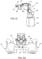
- a robotic surgical assembly 100 comprises a support 104 and one macro-positioning arm 30, connected to said support 104 and having a plurality of degrees of freedom.
- Said macro-positioning arm 30 comprises a support member 38.
- Said robotic surgical assembly 100 comprises at least two micro-positioning devices 41, 141, 241, 341, so as to comprise at least a first micro-positioning device 141 and at least a second micro-positioning device 241, wherein each of said at least two micro-positioning devices 41, 141, 241, 341 has a plurality of motorized degrees of freedom, connected in cascade to said support member 38 of said macro-positioning arm 30.
- motorized degrees of freedom means the provision of motor-driven actuators which determine the movement along a certain degree of freedom.
- said micro-positioning devices 41, 141, 241, 341 provide a plurality of translational degrees of freedom.
- Said robotic surgical assembly 100 comprises at least two medical instruments 60, 160, 260, 360 comprising a first medical instrument 160 and a second medical instrument 260, each of said at least two medical instruments 60, 160, 260, 360 is connected in cascade to each of said micro-positioning device 41, 141, 241, 341.
- a single support member 38 of a macro-positioning arm 30 is connected to at least two medical instruments, by means of at least two micro-positioning devices, and thus it is possible to adjust the orientation of both said two medical instruments 60, 160, 260, 360 by acting on said support member 38 only.
- Each of said at least two medical instruments 60, 160, 260, 360 comprises a shaft 65, suitable for distancing said jointed device 70 from said micro-positioning devices 41, 141, 241, 341 by a predetermined distance in a shaft direction X-X.
- a predetermined distance said jointed device having rotational degrees of freedom from the micro-positioning devices having motorized degrees of freedom.
- the thermal influence of said motor compartment is kept relatively far from the jointed devices. This allows also to miniaturize the dimensions of said jointed device.
- robotic surgical assembly 100 rigidly couples said shaft direction X-X of the shaft 65 of said first medical instrument 160 and said shaft direction X-X of the shaft 65 of said second medical instrument 260;. In this way, it is possible to control the relative orientation of the shaft 65 of said first medical instrument 160 and of the shaft 65 of said second medical instrument 260.
- Said first micro-positioning device 141 provides at least three motorized degrees of freedom of translational motion to said shaft 65 of said first medical instrument 160
- said second micro-positioning device 241 provides at least three motorized degrees of freedom of translational motion to said shaft 65 of said second medical instrument 260. In this way, it is possible to adjust the relative position of said at least two shafts 65 while keeping a predefined relative orientation of said at least two shafts 65.
- the angle between the shaft direction X-X of the shaft 65 of said first medical instrument 160 and the shaft direction X-X of the shaft 65 of said second medical instrument 260 is constant during any motion of any of said plurality of motorized degrees of freedom of said micro-positioning devices 41, 141, 241, 341.
- said at least two micro-positioning devices 41, 141, 241, 341 are rigidly attached to said support member 38.
- said first micro-positioning device 41, 141 rigidly blocks the shaft direction X-X of said first medical instrument 160 and said second micro-positioning device 41, 241 rigidly blocks the shaft direction X-X of said first medical instrument 260.
- said macro-positioning arm 30 includes motorized degrees of freedom.
- the end portions 77 of said first medical instrument 160 and said second medical instrument 260 reach a common workspace volume 7 of a predetermined fixed size, and wherein said macro-positioning arm 30 allows to reposition said common workspace volume 7 in a desired position over the patient anatomy.
- said robotic surgical assembly 100 is suitable to cooperate with a vision system 103, associated with said robotic surgical assembly 100.
- a shaft angle ⁇ is defined as the angle between the shaft direction X-X of the shaft 65 of said first medical instrument 160 and the shaft direction X-X of the shaft 65 of said second medical instrument 260.
- said robotic assembly 100 comprises a support 104 and at least one macro-positioning arm 30, connected to said support 104, with respect to which said macro-positioning arm 30 provides multiple degrees of freedom of macro positioning.
- said micro-positioning device 41, 141, 241 and 341 is connected in cascade, that is in series, to said macro-positioning arm 30.
- a kinematic chain comprising a macro-positioning arm 30 connected in series to at least one micro-positioning device 41 comprising multiple degrees of freedom at least in translation, connected in series with a medical instrument 60, allows to decouple the positioning movements in translationof the terminal portion 77 of said medical instrument 60 within said work volume 7, and the positioning movements in orientation of the terminal portion 77 of said medical instrument 60 within said work volume 7.
- said micro-positioning device 41 comprises degrees of freedom exclusively of translation.
- said at least two micro-positioning devices 141, 241 are placed parallel to each other. According to an embodiment, said at least two micro-positioning devices are placed side-by-side to move one medical instrument on the right and one medical instrument on the left.
- said macro-positioning arm 30 has three degrees of freedom.
- said macro-positioning arm 30 is a passive mechanism.
- said macro-positioning arm 30 is meant to be manually moved by an operator.
- said macro-positioning arm 30 comprises at least one release button 35, or unlocking button, which can be switched between a brake (or lock) and a release (or unlock) position.
- said third sliding direction h-h is substantially orthogonal with respect to both said first sliding direction f-f and said second sliding direction g-g. According to an embodiment, the third sliding direction h-h is aligned with the shaft 65.
- a robotic assembly 100 comprises at least one control device 20, suitable to determine the movement of at least one portion of said medical instrument 60, 160, 260, by a master-slave type communication system.
- said assembly comprises a further control device 20, such that it comprises at least two input devices 20.
- said control device 20 is suitable to determine the motion of said jointed device 70 of said medical instrument 60.
- said control device 20 is suitable to determine the movement of said micro-positioning device 41. The provision of said characteristic allows a translational movement of said control instrument 21 as registered by said detection device 22 to be associated to a translational movement of said terminal device 77 within its workspace 7, 17.
- said vision system 103 is a microscope 103.
- a microscope 103 associable to said robotic assembly allows for retrofitting with pre-existing microscopes, making said robotic assembly 100 more versatile.
- said robotic assembly 100 can be used in cooperation with microscopes that have a focusing distance between 100mm and 500mm, depending on the focal length of the objective lens used.
- it allows the swept volume of the robotic assembly 100 to be reduced, during the surgical operation given that it lacks as many parts as possible that require relatively large movements during the movement of the terminal portion of the instrument.
- said microscope 103 is an optical microscope 103.
- said microscope 103 is suitable to frame in its field of view said terminal portion 77 of said first medical instrument 160 and /or said terminal portion 77 of said second medical instrument 260 and/or said terminal portion of said third medical instrument 360.
- said video-camera 45 is suitable to cooperate with said macro-positioning arm 30 to permit the correct positioning of said at least one medical instrument 60.
- the provision of this characteristic facilitates the positioning process of at least one portion of said at least one medical instrument 60 within the work volume 7.
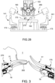
- said first medical instrument 160, said second medical instrument 260 and said support member 38 are disposed in such a way that they substantially form a triangle. Such provision allows to reproduce of the same triangulation existing between the eyes and the arms of the surgeon by means of said robotic assembly 100.
- said support 104 is at least one of: a mobile cart, a support structure of a microscope, an operating bed, an operating table.
- said control instrument 21 comprises at least one forceps articulation 69, effective in a tip portion 68 of said control instrument 21, such as to allow said tip portion 68 a grasping or cutting movement.
- At least one tip sensor 29 measures an opening angle of said forceps articulation 69.
- said ergonomic support element 27 comprises at least one portion made of soft material or foam.
- said control instrument 21 is connected to said detection device 22 by at least one system of electromagnetic communication.
- said position sensor is an electromagnetic position sensor with micro-bobbins and said sensor device comprises a generator of a magnetic field and an electric circuit that reads the circuit induced in said micro-bobbins by said magnetic field. The provision of this characteristic allows the control instrument 21 to preserve its functioning as a traditional surgical instrument, without affecting a response time for said detection device 22.
- control instrument 21 is connected to said detection device 22 by a wireless connection.
- a robotic assembly 100 comprises:
- said terminal portion 77 is suitable to operate on at least one portion of the patient 201.
- said terminal portion 77 is suitable to handle a surgical needle 202, as shown for example in figure 3A-3B.
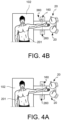
- said control instrument 21 has the same dimensions and offers the same handling experience of a traditional surgical instrument, that is to say a surgical instrument that can be used to operate directly on at least one portion of a patient 201, and said surgical micro-instrument 60 is suitable to replicate the same entire movement capability of said control instrument 21.
- said robotic assembly 100 is suitable to decouple the movements of said control instrument 21 and said surgical micro-instrument 60 in such a way that when the movements of said control instrument 21 are large and comprise vibrations, while the movements of said surgical micro-instrument 60 are filtered of vibrations and reduce the movement to a millimeter or to a micron scale.
- the provision of scaled movement introduced between the master interface and the slave interface allows for the reduction of tremor as well as an improvement of precision of said surgical micro-instrument without decreasing the ease of operation of the surgeon 200.
- said control instrument 21 is suitable to cooperate with said surgical micro-instrument 60 in such a way that, when in operating conditions, at a first 3D movement of said control instrument 21 with respect to said detection device, corresponds to a second 3D movement of said surgical micro-instrument 60.
- said control instrument 21 is suitable to cooperate with said surgical micro-instrument 60, 160, 260, in such a way that, when in operating conditions, a first translational movement of said control instrument 21 corresponds to a second translational movement of said surgical micro-instrument 60, 160, 260 equal to a fraction of the amplitude of said first movement of said control instrument 21. In this way, it is possible to limit the transmission of tremor or vibration of the control instrument 21 to the surgical micro-instrument 60.
- said control instrument 21 is suitable to cooperate with said surgical micro-instrument 60, 160, 260 in such a way that, when in operating conditions, a first translational movement of said control instrument 21 corresponds to a second translational movement of said surgical micro-instrument 60, 160, 260 of an amplitude that is substantially equal to one tenth of the amplitude of said first movement of said control instrument 21.
- said control instrument 21 is suitable to cooperate with said surgical micro-instrument 60, 160, 260 such that, when in operating conditions, a first translational movement of said control instrument 21 corresponds to a second translational movement of said surgical microinstrument 60, 160, 260 of an amplitude substantially equal to one thirtieth of the amplitude of said first movement of said control instrument 21.
- said control instrument 21 is suitable to cooperate with said surgical micro-instrument 60, 160, 260 in such a way that, when in operating conditions, a first angular movement of said control instrument 21 corresponds to a second angular movement of said surgical micro-instrument 60, 160, 260, said second angular movement of the micro-instrument being of an amplitude that is substantially equal to the amplitude of said first movement of the control instrument 21.
- a first angular movement of said control instrument 21 corresponds to a second angular movement of said surgical micro-instrument 60, 160, 260
- said second angular movement of the micro-instrument being of an amplitude that is substantially equal to the amplitude of said first movement of the control instrument 21.
- said control instrument 21 is suitable to cooperate with said surgical micro-instrument 60, such that, when in operating conditions, a first angular movement of said forceps articulation 69 of said control instrument 21 corresponds to a second angular movement of an articulation, situated on said terminal portion 77 of said surgical micro-instrument 60, the amplitude of said second movement being substantially equal to said first angular movement of said forceps articulation of said control instrument 21.
- control instrument 21 is of a shape that substantially reproduces the shape of said terminal portion 77 of said surgical microinstrument 60, 160, 260.
- said at least one control device 20 is connected to at least one portion of said microsurgical robotic assembly 100.
- said surgical micro-instrument 60, 160, 260 comprises at least one micro-instrument sensor, suitable to cooperate with said detection device 22, such that the position in space of at least one portion of the surgical micro-instrument 60, 160, 260 can be detected with respect to said detection device 22.
- said micro-positioning device 41, 141, 241 comprises at least one micro-manipulator sensor, suitable to cooperate with a detection device 22, such as to detect the position in space of at least one portion of said micro-positioning device 41, 141, 241 with respect to said detection device 22.
- said macro-positioning arm 30 comprises at least one macro-positioning arm sensor, suitable to cooperate with said detection device 22, such as to detect the position in space of at least one portion of said macro-positioning arm 30 with respect to said detection device 22.
- said microsurgical robotic assembly 100 is suitable to cooperate with a sensor, suitable to detect the position in space with respect to a single reference system of at least one of: said position sensor 28, said tip sensor 29, said macro-positioning arm sensor, said micro-positioning device sensor, said micro-instrument sensor.
- said microsurgical robotic assembly 100 is suitable to cooperate with a sensor, suitable to detect the position in space with respect to a single reference system of at least two of: said position sensor 28, said tip sensor 29, said macro-positioning arm sensor, said micro-positioning device sensor, said micro-instrument sensor.
- said second control instrument 221 is suitable to cooperate with said second surgical micro-instrument 260, such that, when in operating conditions, a first movement of said second control instrument 221 with respect to said detection device 22, corresponds to a second movement of said surgical micro-instrument 260.
- said first control instrument 121 is suitable to form the master interface of said robotic assembly 100 for one first hand of the surgeon 200.
- said second control instrument 221 is suitable to for the master interface of said robotic assembly 100 for one second hand of the surgeon 200, different from said first hand.
- said first and second control instruments 121, 221 are of substantially mirrored in shapes and location, such as to form the master interface of said robotic assembly 100 for both hands of the surgeon. In this way, the interface has improved ergonomics and is more familiar to the surgeon.
- said first control device 120 is suitable to form the master interface of said robotic assembly 100 for the first hand of the surgeon 200.
- said first and second control devices 120, 220 are of substantially mirrored shapes, such as to form the master interface of said robotic assembly 100 for both hands of the surgeon. In this way, the interface has improved ergonomics and is more familiar to the surgeon.
- a medical instrument 60, 160, 260, 360 comprises at least one frame 57 and one jointed device 70.
- said axes of joint movement can be fixed or mobile with respect to a base reference system.
- said wrist member 78 comprises at least one jointing portion 172, suitable to form at least one portion of a second rotational joint 171 having a second joint axis of movement, not parallel to said first joint axis of movement.
- said first joint axis of movement and said second joint axis of movement are substantially orthogonal to each other.
- said first joint axis of movement is a pitch axis P-P.
- said medical instrument 60, 160, 260 has at least one terminal member 77.
- said jointed device 70 comprises said first member 71, connected to said elbow member 75 by a rotational joint 171, connected to said wrist member 78 by a rotation joint 171, itself connected to said terminal member 77 by a rotational joint 171. It should be apparent to those skilled in the art that making use of joint members similar to 71,72,73, a jointed device 70 can be assembled to include a serial sequence of members, of which from zero to a plurality of elbow joint members 75, a plurality of, preferably orthogonal, pairs of wrist joint members 78 and at least one terminal joint member 77.
- said tendon 90 and said opposite tendon 190 wind their distal portions around at least one portion of said at least one winding surface 86 of terminal member 77.
- said at least one tendon 90, 190 describes a path around said first joint member 71, such as to at least partially wind itself over said joint sliding surface 40, 140 of said first joint member 71.
- said at least one tendon 90, 190 describes a path around said distal second joint member 72, such as to at least partially wind itself over said joint sliding surface 80, 180 of said second joint member 72.
- said medical instrument 60 is suitable for being used for a biopsy. According to an embodiment, said medical instrument 60 is suitable to be used for an endoscopic procedure.
- said tendon drive system 50 comprises at least one further pusher assembly 94, or opposite pusher assembly 194, opposed to said pusher assembly 94 and suitable to push on at least one portion of tendon deflectable portion 93 of said opposite tendon 190, along a transversal pushing direction of tendon T-T such as to deflect the tendon path T-T and to induce an increased tensile load in said opposite tendon 190 and said tendon 90.
- said tendon 90 and said opposite tendon are suitable to work opposed to each other like antagonistic muscles of the human body that cooperate to determine the adduction and abduction movements of a joint.
- said opposite tendon 190 comprises a second endpoint 92, or distal endpoint 92, suitable to pull a mobile element associable to said second tendon endpoint 92 of said opposite tendon 190.
- said tendon 90 and said opposite tendon 190 are two portions of a single tendon 90.
- said second tendon endpoint 92 of said tendon 90 and said second endpoint 92 of said opposite tendon 190 coincide and are suitable for pulling a common mobile element, which can be associated both to said second endpoint 92 of said tendon 90 and to said second tendon endpoint 92 of said opposite tendon 190.
- said opposite tendon 190 comprises at least a longitudinal portion 19, in which the tendon path T-T is substantially parallel to the longitudinal direction of the shaft X-X, such as to move at least said longitudinal portion 19 of said opposite tendon 190 with respect to said shaft 65, at least along the longitudinal direction of the shaft X-X.
- said tendon drive system 50 comprises at least a pair of tendons 90, 190 for each degree of freedom, in which said tendon pair comprises a tendon 90 and an opposite tendon 190.
- said tendon 90 and said opposite tendon 190 are suitable to be simultaneously pulled with substantially the same amount of force.
- said tendon 90 and said opposite tendon 190 are suitable to be simultaneously pulled, retrieving substantially the same tendon length from their proximal portion.
- said tendon 90 is suitable to be pulled, retrieving a first tendon length from its proximal section and simultaneously said opposite tendon 190 is suitable to be released by its proximal portion, releasing a second tendon length from the opposite tendon, substantially equal to said first tendon length.
- said tendon drive system 50 comprises an opposite .pretensioning element 199, suitable for maintaining said opposite tendon 190 pretensioned.
- said pretensioning element 99 and said opposite pretensioning element 199 allows said tendon 90 and said opposite tendon 190 to be kept in their pretensioned state, with a pretension value suitable to counterbalance the weight of said common mobile element attached to them. In this way, the gravitational force has no role in the drive system.
- said tendon drive system 50 comprises a plurality of tendons 90 and a plurality of opposite tendons 190.
- said plurality of tendons 90 and said plurality of tendons 190 are positioned substantially radially, or as rays, on said drum 59.
- said plurality of tendons 90 and said plurality of opposite tendons 190 are configured one said drum 59 like a cylinder of a radial engine, and in which the paths of said tendon 90 and said opposite tendon 190 do not cross each other on said drum 59.
- said tendon 90 of said plurality of tendons 90 is suitable to be engaged by its respective pusher assembly 94 independently of an associated opposite tendon 190.
- a drive system assembly for a medical instrument 60, 160, 260 comprises:
- said tendon 90 and said opposite tendon 190 are both fastened to a same portion of said jointed device 70, 170, 270, mobile with respect to said frame 57, in their respective second endpoints 92, such that said opposite tendon190 is suitable to pull at least a portion of said jointed device 70, 170, 270, moving it with respect to said frame 57 by a movement which is opposite to the movement determined by said tendon 90.
- said drive system assembly comprises a tendon pair 90, 190, and said tendon pair comprises a tendon 90 and an opposite tendon 190, for every degree of freedom of movement of said jointed device 70, 170, 270.
- said medical instrument 60, 160, 260 is at least one of: a surgical instrument, a microsurgical instrument, an instrument for laparoscopic surgery, an endoscopic instrument, an instrument for biopsies.
- a tendon 90, 190 for a medical instrument 60 is suitable to move at least a portion of said jointed device 70 with respect to said frame 57.
- Said jointed device 70 has at least on degree of freedom of movement with respect to said frame 57.
- Said tendon 90 is exclusively suitable for working under tensile load.
- Said tendon 90 is fabricated in a material that is less hard than the material of said jointed device 70.
- this characteristic allows the fabrication of a medical instrument 60 comprising a jointed device 70 with greater resistance to wear, caused by the sliding of tendon 90 over at least a portion of said jointed device 70. Furthermore, this characteristic avoids any wear and loss of material of the surface of the jointed device 70 over which the tendon slides. In other words, the provision of this characteristic avoids said jointed device 70 from becoming scratched due to the effects of the tendon 90 sliding over it, when in operating conditions.
- said tendon 90 slides over at least one portion of said jointed device 70, when in operating conditions.
- said tendon 90 is made of a construction that is not suitable for transmitting pushing.
- said tendon 90 is fabricated of a softer material than the material of said jointed device 70.
- said tendon 90 is fabricated in a polymeric material.
- a tendon that is at least partially fabricated in a polymeric material allows the wear of the surface over which it slides to be reduced, with respect to a tendon made of metal for example, and helps to preserve the geometric tolerances established during the design phase and subsequently prolongs the life of said tendon 90, 190 as well as the life of said medical instrument 60, 160, 260.
- said tendon 90, 190 is made of polyethylene.
- said tendon 90, 190 is made of high molecular weight polyethylene, or UHMWPE.
- said tendon 90, 190 is made of Kevlar.
- said tendon 90, 190 is made of Vectran.
- said tendon 90, 190 is made of Zylon, or PBO.
- said tendon 90, 190 is made of a combination of the above materials.
- said tendon 90, 190 is made of polymer fibers.
- said jointed device 70 is made of a metallic material.
- said jointed device 70 is made of at least one of: INOX steel or stainless steel; super-fast steel; widia; hardened steel; tempered steel; titanium.
- said jointed device 70 is made of a ceramic conductive material.
- said tendon 90 comprises at least one tendon endpoint 91, suitable to be glued to said frame 57.
- said tendon 90 is unraveled into strands around its first tendon endpoint 91 such as to maximize the glued surface.
- said tendon 90 comprises at least a second tendon endpoint 92, suitable to connect to at least a portion of said jointed device 70.
- said second endpoint 92 is a boss. According to an embodiment, said second tendon endpoint is a loop. According to an embodiment, said second tendon endpoint 92 is a knot.
- said second tendon endpoint 92 is glued to at least one portion of said jointed device 70.
- said first tendon endpoint 91 is terminated by wrapping said tendon around a portion of said medical instrument 60 multiple times.
- said second endpoint 92 is terminated by wrapping said tendon around a portion of said medical instrument 60 multiple times.
- said tendon is wrapped around with a curvature radius that is substantially equal to its diameter.
- said tendon 90, 190 has a diameter between 0.05mm and 0.3mm.
- said tendon 90, 190 has an elastic module between 50GPa and 100GPa.
- said tendon 90, 190 is fabricated such as to have a curvature radius inferior or substantially equal to one millimeter.
- said tendon 90 is exclusively suitable to work under tensile load applied at the endpoints, avoiding said tendon to be pinched, to be laterally guided in a channel or to comprise a sheath.
- said tendon 90, 190 is suitable to be pre-lengthened with a load cycle comprising at least two loads of an entity equal to at least half of the tensile breaking strenght of said tendon 90, 190.
- said tendon 90 has a transverse dimension, that is a dimension that is substantially orthogonal with respect to said tendon path T-T, variable in different tendon portions.
- said tendon 90, 190 has a substantially circular cross section.
- the diameter of said tendon 90 is variable in different portions of said tendon 90.
- said tendon 90 is thinner at said second tendon endpoint 92.
- said tendon 90 is thicker in said longitudinal portion 19. This way, the tendon 90, 190 is suitable to be more flexible close to or at the tendon fastening point 82, as well as being stiffer close to or on the inside of said shaft 65.
- the mechanical properties of said tendon 90 are variable in different portions of said tendon 90.
- said tendon 90, 190 is obtained by joining or juxtaposing tendon portions with different characteristics.
- the composition of said tendon 90, 190 is variable in different portions of said tendon 90, 190.
- said tendon 90, 190 has a diameter between 0.1mm and 0.3mm.
- said tendon 90 is suitable to cooperate with an opposite tendon 190 to move at least a portion of said jointed device 70, 170, 270.
- a tendon pair 90, 190 in which every pair comprises a tendon 90 and an opposite tendon 190 is foreseen for every degree of freedom of movement for said jointed device 70.
- a driving method of a surgical robotic assembly comprises the following phases:
- a driving method of a surgical robotic assembly comprises at least one of the following further phases, listed in a preferred, but not necessary order:
- a control method for a control device for microsurgery for a microsurgical robotic assembly comprises the following phase, listed in a preferred but not necessary order.
- one method comprises at least one of the following further phases:
- said portion of the patient 201 is comprised in said work volume 7.
- a method comprises the following further phases:
- one method comprises the following further phases:
- a fabrication method for the medical instrument 60, 160, 260 comprises a phase of fabrication of a medical instrument 60, 160, 260 according to one of any embodiments previously described,. by at least one additive manufacturing technique.
- a fabrication method of a medical instrument 60, 160, 260 comprises a phase of fabrication a medical instrument by micro-injection molding.
- a fabrication method for the medical instrument 60, 160, 260 comprises a phase of fabrication of a medical instrument by means of micromolding.
- a driving method of a tendon 90 for a medical instrument 60, 160, 260 comprises the following phases, listed in a preferred, but not necessary order of execution:
- a method comprises the further phase of providing a drive system assembly according to one of any of the embodiments previously described.
- one method comprises at least one of the following further phases:
- one method comprises the further phases of:
- a method comprises the further phases of:
- one method comprises the following phases instead of the phases I'), J'), K'):
- one method comprises the further phases of:
- a method for replacing a tendon 90, 190 comprises the following phases:
- the tendon 90 is attached first at said second tendon endpoint 92 and then at said first tendon endpoint 91.
- a method comprises the following further phases:
- said plunger (96) is locked by the use of a pin inserted in the plunger locking hole 48.
- one method comprises the following further phases:
- phase D comprises a further sub-phase, which entails the immersion of said medical instrument 60 in a bath of organic solvents.
- said phase A") comprises a further sub-phase of dissolving said any remain of tendon 90.
- said phase A") comprises a further sub-phase of introducing said medical instrument 60 in an autoclave or other sterilization system.
- said phase A") comprises a further sub-phase of introducing said medical instrument 60 in an oven at a temperature between 25°C and 150°C.
- phase A" comprises a sub-phase of immerging of said medical instrument 60 in a chemical organic solvent bath.
- one method comprises the following further phase:
- one fabrication method of a jointed device 70, 170, 270 comprises at least the following phases, in the preferred order indicated below:
- the machining method described above allows the machining of ruled surfaces characterized by parallel generatices on said workpieces 117.
- one machining method as described above allows the cutting of workpieces of very small dimension, for example of millimetric or sub-millimetric dimensions.
- said machining method is suitable to fabricate at least one jointed device 70 that comprises a plurality of joint members 71,72, 73,74, 75, 76, 77, 78.
- said machining method is suitable to machine parallel cuts on said workpieces 117 such as to form joint members comprising surfaces parallel to each other.
- said machining method is suitable for machining parallel cuts on said workpieces 117 such as to form joint members suitable to be assembled in a complementary fashion because they comprise surfaces that are parallel to each other.
- said EDM machine is suitable to perform wire EDM and comprises a cutting wire 115.
- said cutting wire 115, or EDM wire 115, or electrical discharge machine wire 115 is of a diameter between 30 microns and 100 microns, and is preferably of 50 microns.
- said machining method is suitable to fabricate at least one jointed device for applications in the medical-surgical sector.
- said machining method is suitable to fabricate at least one jointed device, suitable for applications in precision mechanics, for example suitable for use in watchmaking. According to an embodiment, said machining method is suitable to fabricate at least one jointed device, suitable for applications in the jewelry and/or fashion jewelry sector. According to an embodiment, said machining method is suitable for the fabrication of at least one jointed device, suitable for applications in the assembly of electromechanical products.
- phase (A′′′) comprises the following sub-phases:
- a sub-phase is first carried out during said phase (A′′′):
- one method comprises the following further phase between the sub-phase (A1′′′) and the sub-phase (A2'”):
- one method comprises the following further phase between the phase (A′′′) and the phase (B′′′):
- one method comprises the following further phases after the phase (B′′′).
- said phase of rotating said machining fixture 112 comprises a further phase of using a rotary table to rotate said machining fixture 112, avoiding to dismount said machining fixture 112 from the cutting machine to carry out the following phases:
- phase (C′′′) carry out a calibration, comprises the following sub-phases:
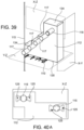
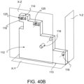
- said machining fixture 112 is suitable to perform at least two cuts on different cutting planes on workpieces 117 by using a single cutting profile 110 per cutting plane.
- said machining fixture 112 comprises a second pair of fixing surfaces 134, 135, which are rectified, opposite and substantially parallel to each other and substantially orthogonal to a second plane of cutting Y-Z.
- each pair of locating surfaces comprises at least one base fixing surface 113, 135 and at least one fixture fixing surface 114, 134.
- said plurality of member seat 116 are sequentially arranged such that a translating straight line, substantially orthogonal to said first cutting plane X-Y, or substantially orthogonal to said second cutting plane Y-Z, would intersect at most only one of said workpieces 117 at a time, when said workpieces are mounted in respective member seats 116.
- said member seats 116 are susbstantially parallel to each other.
- said machining fixture 112 also comprises a pair of locating surfaces, opposite and substantially parallel to each other and substantially orthogonal to a third cutting plane X-Z.
- said third pair of locating surfaces comprises at least a guide hole 125, and the EDM wire 115 of said EDM machine is inserted in at least one said guide hole 125, to avoid the EDM wire coming into contact with at least one machining fixture 112, during the cut.
- said machining fixture 112 also comprises: . a plurality of member seats 116, each suitable to receive at least one workpiece 117, said workpiece 117 being suitable to realize at least one portion of said jointed device 70, 170, 270.
- said machining fixture 112 also comprises at least one reference rod 118, suitable to allow for the cut calibration.
- said machining fixture 112 comprises at least one fixing element, or fastening element, suitable to firmly connect said at least one workpiece 117 in its respective member seat 116.
- said at least one fastening element is conductive glue.
- said grub screw is suitable to be mounted in a threaded hole supplied in said at least one fastening surface.
- said fastening grub screw is suitable to penetrate in said threaded hole of said fastening surface.
- said machining fixture 112 comprises four member seats 116 and a reference rod 118.
- each member seat 116 is substantially positioned at the same distance from its respective fastening surface.
- said fastening surfaces are positioned in a stepwise manner, such as to form a stair shape in profile.
- said fastening surfaces are positioned in a stepwise manner, such as to form a stair shape in profile with respect to at least one cutting plane X-Y, Y-Z, X-Z.
- said machining fixture 112 has a surface facing towards any cutting plane X-Y, Y-Z, X-Z inferior to 10000 square millimeters.
- said machining fixture 112 has a surface facing towards any cutting plane X-Y, Y-Z, X-Z inferior to 5000 square millimeters.
- a medical instrument 60, 160, 260, 360 includes:
- said pushing element 95 pushes on a plunger 96 in a pushing direction directed towards the inside of said frame 57, to move said plunger 96 along its degree of freedom with respect to said frame 57.
- said pushing element 95 exchanges with said plunger 96 a force that is always directed in said pushing direction.
- said pushing element 95 is not suitable to exchange with said plunger 96 a pulling force, in other words said pushing element 95 cannot pull said plunger 96.
- said pushing element 95 includes a lead screw and nut type actuator.
- said actuator includes a ball screw.
- said pushing element 95 includes a piston.
- said plunger 96 has two portions one first portion of plunger 145 suitable to be in contact with said pushing element 95 and one second portion of plunger 146 to suitable to be in contact with said tendon 90, 190.
- said first portion of plunger 145 is exposed from the frame 57 to be pushed by said pushing element 95.
- said first portion of plunger 145 extends outside of frame 57 to be accessible by said pushing element 95.
- said first portion of plunger 145 is flush with said frame 57 to be accessible by said pushing element 95.
- said first portion of plunger 145 includes a pushing surface 147 suitable to be engaged with said pushing element 95.
- said pushing elements 95 has a reciprocal pushing surface 148
- said pushing element 95 pushes said plunger 96 transmitting a linear force through said a reciprocal pushing surface 148.
- said pushing element 95 pushes said plunger 96 transmitting a linear force through said one pushing element idle pulley.
- said pushing surface 147 and reciprocal pushing surface 148 are flat.
- said pushing surface 147 and reciprocal pushing surface 148 are curved surface that mate with each other.
- said pushing surface 147 and reciprocal pushing surface 148 are sliding surfaces that slide with respect to each other as said pushing element 95 moves along a linear trajectory.
- said second portion of plunger 96 in contact with said tendon 90,190.
- said medical instrument 60, 160, 260, 360 includes at least one tensioning element 99, suitable for impose a preload on said tendon 90.
- said tensioning element 99 is a spring.
- said tensioning element 99 is suitable to apply a force between the frame 57 and the plunger 96, in the direction of moving said plunger 96 away from said pushing element 95.
- said preload is substantially proportional to the compression movement of said spring 99.
- said second portion of plunger 146 pushes on at least one tendon deflectable portion 93 of said tendon 90.
- said tendon deflectable portion 93 of said tendon 90 extends from a first guiding pulley 197 and second guiding pulley 297.
- said tendon 90 has a first tendon endpoint 91 fastened to said joint member 71, 72, 73, 74.
- said tendon 90 has a second tendon endpoint 91 fastened to said frame 57.
- said frame 57 includes a upper frame portion 58 and a lower frame portion 59 the latter including a shaft 65.
- said plunger 96 is jointed to said lower frame portion 58 with a rotational joint not represented.
- said plunger 96 moves linearly along a degree of freedom with respect to said frame57.
- said plunger 96 is maintained in a proper alignment by means of linear bushings not represented inserted in the first frame section 58.
- said plunger 96 is maintained in a proper alignment with upper frame 58 by means of respective shoulder surfaces 88.
- said plungers 96 is a rocker that rotates around a pivot of said frame 57.
- said sterile barrier 87 is of a form and material suitable to transmit the push of said pushing element 95 to said plunger 96.
- said sterile barrier 87 is a flexible continuous layer of material.
- said sterile barrier 87 lays in between said pushing element 95.
- said sterile barrier 87 is trapped between said pushing surface 147 and said reciprocal pushing surface 148.
- said medical instrument 60, 160, 260, 360 includes a plurality of tendons 90 and of pairs of plungers 96 and associated pushing element 95.
- said sterile barrier 87 is a flexible continuous layer of material.
- said sterile barrier 87 is made of a streachable material that streaches as said plungers 96 move with respect to said frame 57 exerting forces that do not substantially impede the motion of said plungers 96.
- said sterile barrier 87 is a drape.
- said sterile barrier 87 is a loose fitting drape that streaches as said plungers 96 move with respect to said frame 57 exerting forces that do not substantially impede the motion of said plungers 96.
- a sterile barrier 87 of a medical instrument 60, 160, 260, 360 it is possible to provide a sterile barrier that is not attached to pushing element and so it is easier to deploy for the surgical staff.
- said pushing element 95 includes a sensor 150 suitable to detect contact between said pushing element 95 and said plunger 96 through said sterile barrier 87.
- said force sensor 151 is a mono-axial load sensor measuring a component of pushing force along the linear trajectory of motion of said pushing element 95.
- a sensor 150 of a medical instrument 60, 160, 260, 360 it is possible to sense through a sterile barrier a sensed quantity related to the interaction between said jointed device 70 and patient 201 anatomy.
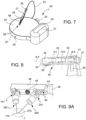
- a possible configuration of the surgical robotic assembly 100 is composed of: a support 104 which allows for the support of the surgical robotic assembly 100 and for its transfer into the operating room to a position adjacent to the mobile operating table 102 on which the patient 201 is lying, one passive, articulated macro-positioning arm 30 that extends from the support 104 and allows the active part of the surgical robotic assembly 100 to reach the anatomical site involved in the procedure.
- Said foot platform 105 allows the foot of an operator responsible for the movement of said robotic assembly 100 to rest on it, such that the robotic assembly 100 can also be pushed from the base, eliminating the risk of its tipping over while it is moved.
- a power and communication tendon 24 connects the magnetic field generator to the external power source at the cart 104 of the robotic assembly, transferring the data relative to the position and orientation of the control instrument as well as the aperture angle of the forceps of the control instrument 21.
- a further marker for the detection of the six spatial coordinates of the cart with respect to the base structure 67 is present on the support 104 and connected by the power and communication tendon 24 to the base structure 67.
- Status signal lights 26 are integrated in the base structure 67 and communicate the activity of the control device to the user.
- a soft, dedicated, ergonomic operator support 27 is made to allow an ergonomic use of the control device 20, while the control instrument 21 reproduces the geometry of traditional micro-instruments such as the forceps and needle holder to make their handling more intuitive and familiar to the surgeon.
- the first member 31 of the macro-positioning arm 30 is connected to a cart 104 by a rack and pinion mechanism that allows to manually control the movement of said macro-positioning arm 30 within a dedicated linear sliding guide36 along a preferably vertical linear displacement axis, when a manual knob 37 is turned.
- the macro-positioning arm 30 is connected to the support member 38 via the rotational joint, which is manually activated via the movement of said rotational dial nut 43.
- a pair of micro-positioning devices 41, 141, 241 is connected to the two extremities of said support member 38 that also carries a video camera 45 in its middle section, which can display enlarged images of the work volume 7 in which the microsurgery is carried out.
- the medical instruments 60, 160, 260 are rigidly attached to a distal portion of the micro-positioning devices 41, 141, 241.
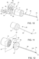
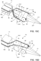
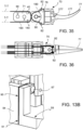
- the medical instrument 60 is made of a motor box 61 containing the actuators for driving the medical instrument 60, the associated electronic control boards and motor driver boards.
- the mechanical transmission box 62 which contains the mechanisms dedicated to transmit the motor motion via said shaft 65 along the longitudinal shaft direction X-X, to the jointed device and the terminal device 77, is connected to said motor box 61.
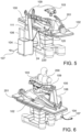
- the motor box 61 contains six pushing elements 95 associated to three degrees of freedom of the medical instrument 60.
- said pushing elements are moved by at least one pusher assembly 94, which comprises electric micro-motors with a linear transmission system lead screws.
- Actuation pistons 95 come out of the wall of motor box 61 facing the transmission box 62 and actuate the transmission mechanism integrated into the mechanical transmission box 62.
- the motor box 61 and the mechanical transmission box 62 are separated by a sterile barrier 87 and can be integrally connected with each other by connecting features, for example via a bayonet connection, as shown in figure 12 .
- the shaft 65 is hollow, fabricated in metal, extends itself along the longitudinal shaft direction X-X and inserts itself into the mechanical transmission box 62.
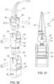
- the jointed device 70, 170, 270 with the terminal device 77 at the tip is inserted at the other shaft end or tip.
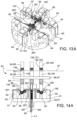
- the six pushing elements 95 implemented as actuation pistons connected to motors, couple with the respective plungers 96 of the mechanical transmission box 62 thus connecting the motor box 61 with the mechanical transmission box 62,
- said pushing element 95 and said plungers 96 are separated by a sterile barrier 87.
- the plungers 96 can move linearly along the piston movement axis and are maintained in a proper alignment by means of linear bushings not represented inserted in the first frame section 58, or upper frame 58, and by means of respective shoulder surfaces 88.
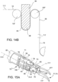
- the actuation of the jointed device 70 is assigned to six tendons 90, or actuation cables 90, which are independent and run from a tendon fastening surface 84 in the mechanical transmission box 62, to the jointed device 70 of the medical instrument 60, via the mechanical transmission box 62, the tendon passage hole and the hollow shaft 65.
- the movement of the plunger 96 and hence of the plunger idle pulley 98 induced by the actuation piston 95 pushes the tendon 90 and hence varies its path length between said first guiding pulley 197 and said second guiding pulley 297.
- This change in length is transmitted by means of said transmission mechanism to the distal articulation of the medical instrument 60, 160, 260, resulting in its actuation.
- a tendon guide element 89 maintains each tendon 90 in position and impedes its derailing, even in cases of anomalies such as a loss of tension in the tendons 90.
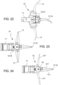
- the jointed device 70 uses six low-friction, low minimum curvature radius and high stiffness polymeric tendons as movement transmission means for actuation of the three degrees of freedom of motion which the jointed device 70, 170, 270 is capable of.
- all holes, being machined by wire EDM such as the pin holes 79, have extra machining grooves 49 resulting from the passage of the cutting wire 115.
- the first member 71 presents two opposite tendon sliding surfaces 40, 140 each having rounded shapes that are symmetrically opposite i.e. mirrored with respect to said section plane.
- each sliding surface 80, 180, 40, 140 is resulting from the sweeping motion of parallel straight generatrices that move directly along a cutting profile 110.
- the third member 73 is characterized by a pin hole 79 located around the second axis of joint movement Y-Y.
- the third member 73 is mated to the second member 72 by a seat for a joint pin and an associated lateral shoulder surface.
- a winding surface 86 of the actuation cables 90, 190 allows the winding of the actuation cables 90, 190 around that winding surface 86 that is concentric to the second axis of joint movement Y-Y.
- a terminal member 77 can be individually jointed to said second member 72, only if the terminal device 77 is itself a medical instrument 60 of a surgical or microsurgical type similar for example to a scalpel blade or to a fiber-optic tendon carrier for laser light treatments.
- the jointed device 70 will only comprise two degrees of freedom of movement, in particular of pitch and yaw, losing the degree of freedom for grasping.
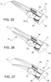
- the first portion of terminal member 177 and the second portion of terminal member 277 can mate with each defining different terminal devices 77, such as a micro device for cutting, a terminal micro device providing a straight grasp, a micro device providing angled grasping, a needle holder and other traditional microsurgical instruments as illustrated in figures 25-27 .
- the terminal devices reproduce the form, proportions and functionalities of traditional microsurgical instruments tips, in order to facilitate their recognition and use by the microsurgeon 200.
- fastening pins 76 are inserted in the pin holes 79 of the members of the jointed device 70.
- the fastening pins 76 are preferentially made of hard metal, rectified and polished to reduce sliding friction.
- the fastening pins 76 have lee way, or clearance, in the pin holes 79 associated to the winding surfaces 86.
- connection by fastening pins 76 between the first member 71 and the second member 72 forms a rotational joint, suitable to rotate around the second axis of joint movement P-P, with an associated actuation angle substantially comprised between +90° and -90°.
- connection by a single fastening pin between the second joint member 72, the first portion of terminal member 177 and the second portion of terminal member 277 creates a rotational joint between said three members 72, 177, 277 with an associated actuation angular range substantially between +90°and -90°.
- Said joint defines two degrees of freedom, characterizing both the yaw and the grasp of the medical instrument 60.
- the polymeric tendons 90, 190 can be terminated in several ways, provided that, as a result of strong fastening, they can be tensioned and such a tension is also transmitted to the joint member, or to the part to which they are connected, driving its motion.
- the tendons 90 run through a tendon termination feature 82 and are locked by a knot formed by the tendon 90 itself, located at said tendon fastening point 82.
- a second method for fastening the tendon 90 used for example for the actuation of the second member 72, provisions the passage of a loop of the tendon 90 around a tendon fastening point 82 and the application of tension to both the extremities of the tendon 90, such that the two sides of the tendon 90 act as a single tendon 90, halving the loads to which it is subject.
- a third fastening method of the tendons 90 provisions the insertion of tendon portions in tendon fastening points 82, intended for this use, and the use of glues specific for the polymer of which the tendons 90 are made, such as those used for example for glueing the first endpoint 91 to the lower frame 59 of the mechanical transmission box 62 of the tendon drive system 50.
- the jointed device 70 is characterized by three degrees of freedom of movement, and in particular by one degree of freedom of pitch between the first member 71 and the second member 72, one degree of freedom of yaw between the second member 72 and the third member 73, one degree of freedom of gripping, or grasping, between the first portion of terminal member 177 and the second portion of terminal member 277.
- the second joint member 72, the first portion of the terminal member 177 and the second portion of the terminal member 277 can move around respectively said first axis of joint movement P-P and said second axis of joint movement Y-Y independently.
- the movement of the medical instrument 60 is carried out by the actuation cables 90, which run over the members jointed to each other by rotational joints.
- one of the two tendons 90, 190 When one of the two tendons 90, 190 is tensioned or released, it slides on a sliding surface 40 of the first joint member 71 and over sliding surface 80 of the second joint member 72, while it winds itself or unwinds over the winding surface 86 of the fourth joint member like over a fixed pulley.
- a further tendon pair 90, 190 consisting of a tendon 90 and an opposite tendon 190, actuates the first portion of terminal member 177 in a similar fashion to the way the second portion of terminal member 277 is actuated.
- a yet further tendon pair 90, 190 consisting of a tendon 90 and an opposite tendon 190, suitable to work as a pair of agonistic and antagonistic tendons, move second joint member 72 around first axis of joint movement P-P, running over the lateral sliding surface 40, 140 of the first member 71, on one side with respect to said section plane of the medical instrument 60, intersecting said section plane, winding themselves in the opposite directions on the joint sliding surface 80 of the second joint member 72, and terminating at tendon fastening points 82.
- each actuation tendon 90, 190 of the second joint member 72 is formed in a loop that passes around respective tendon fastening point 82 and comes back doubled up, passing over the winding surface 86, joint sliding surface 80 and lateral sliding surface 40 along a path analogous to that followed by the opposite tendon.
- both the end of the tendons 90, 190 are subject to tension. Furthermore, differently from the two tendon pairs 90, 190 that actuate the first portion of terminal member 177 and the second portion of terminal member 277 respectively, in the case of tendons 90 of the second joint member 72, the tendons 90, when moving, do not slide over the sliding surface of the second joint member 72, but wrap or unwrap around said joint sliding surface 80, as though it were a pulley.
- tendons 90 are used for the actuation of the threes degrees of freedom of movement of the jointed device 70, but eight cables intersect on said section plane between the lateral sliding surface 40 of the first joint member and the lateral sliding surface 80 of the second joint member 72, because both loop ends of the actuation cables 90, 190 of the second member 72 are tensioned during the movement in one direction around the first axis of joint movement P-P.
- the sliding surfaces 80, 180 between the actuation cables 90 and members of the jointed device 70 are reduced to a minimum surface area, such as to reduce friction.
- the tendons 90, 190 are terminated at their second tendon end points 92 such a way that their tendon path T-T remains parallel to the instrument axis X-X as much as possible, avoiding transversal forces.
- the intersection of the tendons 90 and their crossing of said section plane between the joint sliding surface 40 and the first axis of rotation P-P prevents the tendon 90 from leaving the joint sliding surface 80 during its movement and guarantees a constant length and angle of the tendons 90, 190.
- EDM is a subtractive fabrication process in which material is removed by a conductive piece with a series of current discharges between the piece itself and an electrode kept at an electrical voltage difference, separated by a dielectric liquid such as water or oil, until the desired shape is obtained.
- a metal cutting wire 115 made of copper or brass for example, and of a diameter varying between 0.5mm and 0.02mm, continuously runs between two bobbins.
- the cutting wire 115 is sustained by an upper guide and a lower guide, which being driven by a computer numeric control system in the horizontal plane, carry out two-dimensional cutting profiles.
- the movement of the guides is very precise, and the overall machining resolution is close to 1micron ( ⁇ m), nevertheless, the planar cut substantially limits the fabrication of three-dimensional parts.
- some advanced machines have an upper guide, which can move independently in the horizontal plane, the ability to produce complex 3D parts has not substantially increased.
- wire EDM The primary advantages of wire EDM comprise:
- a machining fixture 112 in order to substantially decrease the fabrication time and guarantee the precision required for the correct mating of the fabricated micro-parts, a machining fixture 112 is provided, which intended specifically for this use. It provides a mechanical support, which allows the simultaneous fastening and machining of all the workpieces 117, simplifying assembly of at least a portion of a jointed device 70 on one or more difference planes, with a single cutting profile 110 and a single calibration step.
- the frontal plane of the machining fixture 112 has member holes 116, suitable to hold the workpieces 117 with very tight tolerance, that is to say at least H6h5.
- the frontal plane of the machining fixture 112 has a "stepped" profile to allow threading short through holes on the stepped lateral planes.
- grub screws M2 fasten the workpieces 117 to the machining fixture 112 and guarantee a perfect electrical conductivity with said machining fixture 112, which fundamental for a successful EDM process.
- an alternative to the grub screws and to the threaded holes associated to the grub screws is the use of conductive glue, to fasten the workpieces 117 to the machining fixture 112 and guarantee a perfect electrical conductivity with said machining fixture 112.
- the gap, or non-overlapping section, between two adjacent workpieces is minimized such as to keep the dimensions of the machining fixture 112 as compact as possible. In this way it is possible to minimize the distance between the upper and lower guides, improving the machining precision.
- a metallic reference rod 118 is inserted in the machining fixture 112 and is used for calibration of the EDM machine once the machining fixture 112 and the workpieces 117 are mounted on the machine.
- a first calibration is provisioned, which is carried out only once for a given machining fixture 112, loaded with all the workpieces 117 and a given EDM machine being used for the machining.
- Said first calibration is capable to identify and compensate all errors related to the EDM machine and to the geometric errors of the machining fixture 112, such as for example those related to the relative position between the reference rod 118 and the workpieces 117.
- the cutting profiles 110 are generated, taking into account of any differences of the actual positions with the nominal ones.
- said first calibration will be repeated only if the EDM machine is changed or a new machining fixture 112 is being used.
- This cut calibration process eliminates geometric offset and errors related to the manual fastening of the fixture and identifies the origin of the machine reference system with respect to the axis of the reference rod.
- said machining fixture 112 has at least a pair of fastening or fixing surfaces 113, 114, opposite and parallele to each other, and rectified, meant to be gripped by the jaws of the vise, and a flat posterior X-Z surface, rectified and orthogonal to the fixing surfaces 113, 114, meant to be flush with an reference surface of the machine, orthogonal to the vise's clamp.
- the machining fixture 112 have a pair of fixing surfaces 113, 114 that are flat, parallel and rectified, opposite to each other for each cut plane provisioned for the fabrication of the micro-components.
- the fabrication process used for the fabrication of parts of a jointed device 70 provisions the insertion of four workpieces 117 composed of metallic cylinders made of tool steel, into member holes 116 on the front side of said machining fixture 112 and then their fastening with grub screws of M2 size.
- all three-dimensional micro-part that form the jointed device 70 for micro-medical applications are machined from metallic workpieces 117, in particular steel cylinders of 3 millimeter outer diameter and 12 millimeter length, that are machined by wire EDM on two planes, X-Y and Y-Z.
- the machining fixture 112 loaded with the workpieces 117 is secured on the vise of the EDM machine by using the fixing surfaces 113, 114 as reference planes for the fastening and then the calibration in the X-Y plane is performed using the axis of the reference rod 118, rigidly attached to the machining fixture 112, as a reference.
- the first cutting profile 110 is performed, machining all the workpieces 117 fastened to the machining fixture 112, in the X-Y plane.
- the machining fixture 112 is then removed from the machine and remounted, rotated by 90° to machine along said second plane Y-Z of the machining fixture 112.
- a second calibration for the second work plane Y-Z is performed and then the cut of the second cut profile 210 is carried out.
- the components produced are completely detached from the workpiece and can be collected in the EDM machine bath.
- a robotic assembly having as few moving parts as possible that require a large range of movement during the movement of the terminal portion of the medical instrument, it is possible to provide a microsurgical robotic assembly of low encumbrance, improving the comfort of the micro-surgeon, who can, for example, tele-operate while being in the immediate vicinity of the operating table and hence can see and directly access the operating field, as well as improving the overall working conditions of the surgical team, by, for example, avoiding collisions with mobile parts of the robot while accessing the operating field, as well as simplifying the transport of the robotic assembly, or the flow of people or air around the robotic assembly. Equally, it becomes possible to use two or more robotic assemblies simultaneously on one patient.
- control instrument is also suitable to replicate the functionality of traditional surgical or microsurgical instruments, while allowing a complete freedom of movement in the three dimensions of space and allowing easy repositioning of the control device, for example between the operating table and the microscope, still guaranteeing good performance of the robotic system in terms of response time.
- a control instrument which replicates the shape of a traditional microsurgical instrument having at least one joint at its tip, such as for example tweezers of forceps, equipped with at least one aperture sensor, it is possible to control the opening and closing, as well as grip movements of a jointed medical device in a familiar and precise manner.
- a tendon according to an embodiment, produced of non-metallic material, for example polymeric material, it is possible to reduce the curvature radius of said tendon, as well as the friction coefficient of said tendon, and consequently increase the miniaturization of the medical instrument that comprises said tendon.
- the shaft 65 of said medical instrument can measure 3 millimeter in outer diameter.
- a robotic assembly comprising a macro-positioning arm having a mechanical structure of arm members, as well as highly rigid joints, it is possible to avoid structural mechanical vibrations at the terminal portion of the instrument, and hence facilitate the surgeon's work.
Landscapes
- Health & Medical Sciences (AREA)
- Engineering & Computer Science (AREA)
- Life Sciences & Earth Sciences (AREA)
- Surgery (AREA)
- Veterinary Medicine (AREA)
- Animal Behavior & Ethology (AREA)
- Nuclear Medicine, Radiotherapy & Molecular Imaging (AREA)
- Biomedical Technology (AREA)
- Heart & Thoracic Surgery (AREA)
- Medical Informatics (AREA)
- Molecular Biology (AREA)
- Public Health (AREA)
- General Health & Medical Sciences (AREA)
- Robotics (AREA)
- Mechanical Engineering (AREA)
- Pathology (AREA)
- Oral & Maxillofacial Surgery (AREA)
- Physics & Mathematics (AREA)
- Radiology & Medical Imaging (AREA)
- Biophysics (AREA)
- Manufacturing & Machinery (AREA)
- General Physics & Mathematics (AREA)
- Automation & Control Theory (AREA)
- Human Computer Interaction (AREA)
- Optics & Photonics (AREA)
- Ophthalmology & Optometry (AREA)
- Chemical & Material Sciences (AREA)
- Chemical Kinetics & Catalysis (AREA)
- Electrochemistry (AREA)
- Manipulator (AREA)
- Surgical Instruments (AREA)
Applications Claiming Priority (4)
| Application Number | Priority Date | Filing Date | Title |
|---|---|---|---|
| ITMI201562500 | 2015-10-16 | ||
| ITUB2015A005057A ITUB20155057A1 (it) | 2015-10-16 | 2015-10-16 | Assieme robotico di chirurgia |
| PCT/EP2016/074805 WO2017064301A1 (en) | 2015-10-16 | 2016-10-14 | Robotic surgical assembly |
| EP16781489.6A EP3361980B1 (de) | 2015-10-16 | 2016-10-14 | Chirurgische roboteranordnung |
Related Parent Applications (2)
| Application Number | Title | Priority Date | Filing Date |
|---|---|---|---|
| EP16781489.6A Division EP3361980B1 (de) | 2015-10-16 | 2016-10-14 | Chirurgische roboteranordnung |
| EP16781489.6A Division-Into EP3361980B1 (de) | 2015-10-16 | 2016-10-14 | Chirurgische roboteranordnung |
Publications (2)
| Publication Number | Publication Date |
|---|---|
| EP4393653A2 true EP4393653A2 (de) | 2024-07-03 |
| EP4393653A3 EP4393653A3 (de) | 2024-09-25 |
Family
ID=55237855
Family Applications (6)
| Application Number | Title | Priority Date | Filing Date |
|---|---|---|---|
| EP21210393.1A Pending EP3977957A3 (de) | 2015-10-16 | 2016-10-14 | Chirurgisches instrument für die roboterchirurgie und roboterchirurgische anordnung |
| EP25158176.5A Pending EP4530024A3 (de) | 2015-10-16 | 2016-10-14 | Robotische chirurgische anordnung |
| EP16781489.6A Active EP3361980B1 (de) | 2015-10-16 | 2016-10-14 | Chirurgische roboteranordnung |
| EP16781490.4A Active EP3361981B1 (de) | 2015-10-16 | 2016-10-14 | Chirurgisches instrument für die roboterchirurgie und roboterchirurgische anordnung |
| EP22216898.1A Pending EP4218650A3 (de) | 2015-10-16 | 2016-10-14 | Medizinisches instrument und robotische chirurgische anordnung |
| EP24176173.3A Pending EP4393653A3 (de) | 2015-10-16 | 2016-10-14 | Robotische chirurgische anordnung |
Family Applications Before (5)
| Application Number | Title | Priority Date | Filing Date |
|---|---|---|---|
| EP21210393.1A Pending EP3977957A3 (de) | 2015-10-16 | 2016-10-14 | Chirurgisches instrument für die roboterchirurgie und roboterchirurgische anordnung |
| EP25158176.5A Pending EP4530024A3 (de) | 2015-10-16 | 2016-10-14 | Robotische chirurgische anordnung |
| EP16781489.6A Active EP3361980B1 (de) | 2015-10-16 | 2016-10-14 | Chirurgische roboteranordnung |
| EP16781490.4A Active EP3361981B1 (de) | 2015-10-16 | 2016-10-14 | Chirurgisches instrument für die roboterchirurgie und roboterchirurgische anordnung |
| EP22216898.1A Pending EP4218650A3 (de) | 2015-10-16 | 2016-10-14 | Medizinisches instrument und robotische chirurgische anordnung |
Country Status (11)
| Country | Link |
|---|---|
| US (8) | US10864051B2 (de) |
| EP (6) | EP3977957A3 (de) |
| JP (4) | JP6942360B2 (de) |
| KR (3) | KR102657020B1 (de) |
| CN (3) | CN113768629B (de) |
| AU (3) | AU2016337026B2 (de) |
| BR (2) | BR112018007640B1 (de) |
| CA (2) | CA3001934C (de) |
| ES (2) | ES3031441T3 (de) |
| IT (1) | ITUB20155057A1 (de) |
| WO (2) | WO2017064301A1 (de) |
Families Citing this family (229)
| Publication number | Priority date | Publication date | Assignee | Title |
|---|---|---|---|---|
| US8496647B2 (en) | 2007-12-18 | 2013-07-30 | Intuitive Surgical Operations, Inc. | Ribbed force sensor |
| US8628518B2 (en) | 2005-12-30 | 2014-01-14 | Intuitive Surgical Operations, Inc. | Wireless force sensor on a distal portion of a surgical instrument and method |
| US9232959B2 (en) | 2007-01-02 | 2016-01-12 | Aquabeam, Llc | Multi fluid tissue resection methods and devices |
| US12290277B2 (en) | 2007-01-02 | 2025-05-06 | Aquabeam, Llc | Tissue resection with pressure sensing |
| US8561473B2 (en) | 2007-12-18 | 2013-10-22 | Intuitive Surgical Operations, Inc. | Force sensor temperature compensation |
| JP5506702B2 (ja) | 2008-03-06 | 2014-05-28 | アクアビーム エルエルシー | 流体流れ内を伝達される光学エネルギーによる組織切除および焼灼 |
| WO2012049623A1 (en) | 2010-10-11 | 2012-04-19 | Ecole Polytechnique Federale De Lausanne (Epfl) | Mechanical manipulator for surgical instruments |
| US12402960B2 (en) | 2010-10-11 | 2025-09-02 | Ecole Polytechnique Federale De Lausanne (Epfl) | Mechanical manipulator for surgical instruments |
| EP3588217A1 (de) | 2011-07-11 | 2020-01-01 | Board of Regents of the University of Nebraska | Robotische chirurgische vorrichtungen, systeme und entsprechende verfahren |
| JP5715304B2 (ja) | 2011-07-27 | 2015-05-07 | エコール ポリテクニーク フェデラル デ ローザンヌ (イーピーエフエル) | 遠隔操作のための機械的遠隔操作装置 |
| EP3730031A1 (de) | 2011-10-03 | 2020-10-28 | Board of Regents of the University of Nebraska | Robotische chirurgische vorrichtungen und systeme |
| CN108606773B (zh) | 2012-02-29 | 2020-08-11 | 普罗赛普特生物机器人公司 | 自动化图像引导的组织切除和处理 |
| WO2014011238A2 (en) | 2012-05-01 | 2014-01-16 | Board Of Regents Of The University Of Nebraska | Single site robotic device and related systems and methods |
| EP4234185A3 (de) | 2012-06-22 | 2023-09-20 | Board of Regents of the University of Nebraska | Robotische chirurgische vorrichtungen mit lokaler steuerung |
| CA2880622C (en) | 2012-08-08 | 2021-01-12 | Board Of Regents Of The University Of Nebraska | Robotic surgical devices, systems and related methods |
| US12295680B2 (en) | 2012-08-08 | 2025-05-13 | Board Of Regents Of The University Of Nebraska | Robotic surgical devices, systems and related methods |
| US10231867B2 (en) | 2013-01-18 | 2019-03-19 | Auris Health, Inc. | Method, apparatus and system for a water jet |
| WO2014152418A1 (en) | 2013-03-14 | 2014-09-25 | Board Of Regents Of The University Of Nebraska | Methods, systems, and devices relating to force control surgical systems |
| US10744035B2 (en) | 2013-06-11 | 2020-08-18 | Auris Health, Inc. | Methods for robotic assisted cataract surgery |
| CA2918531A1 (en) | 2013-07-17 | 2015-01-22 | Board Of Regents Of The University Of Nebraska | Robotic surgical devices, systems and related methods |
| US10426661B2 (en) | 2013-08-13 | 2019-10-01 | Auris Health, Inc. | Method and apparatus for laser assisted cataract surgery |
| US10550918B2 (en) | 2013-08-15 | 2020-02-04 | Intuitive Surgical Operations, Inc. | Lever actuated gimbal plate |
| US10076348B2 (en) | 2013-08-15 | 2018-09-18 | Intuitive Surgical Operations, Inc. | Rotary input for lever actuation |
| JP6220085B2 (ja) | 2014-02-03 | 2017-10-25 | ディスタルモーション エスエーDistalmotion Sa | 交換可能な遠位装置を備える機械的遠隔操作デバイス |
| EP3182951A1 (de) * | 2014-08-18 | 2017-06-28 | Ondal Medical Systems GmbH | Kraft- oder bewegungsreaktive stativvorrichtung, steuerungseinrichtung sowie verfahren zum positionieren der stativvorrichtung |
| EP3185808B1 (de) | 2014-08-27 | 2022-02-23 | DistalMotion SA | Chirurgisches system für mikrochirurgische verfahren |
| EP3689257B1 (de) | 2014-11-11 | 2024-01-03 | Board of Regents of the University of Nebraska | Robotische vorrichtung mit kompaktem gelenkentwurf sowie zugehörige systeme und verfahren |
| US11039820B2 (en) | 2014-12-19 | 2021-06-22 | Distalmotion Sa | Sterile interface for articulated surgical instruments |
| US10864049B2 (en) | 2014-12-19 | 2020-12-15 | Distalmotion Sa | Docking system for mechanical telemanipulator |
| WO2016097868A1 (en) | 2014-12-19 | 2016-06-23 | Distalmotion Sa | Reusable surgical instrument for minimally invasive procedures |
| EP3232951B1 (de) | 2014-12-19 | 2023-10-25 | DistalMotion SA | Chirurgisches instrument mit gelenkigem endeffektor |
| EP3232974B1 (de) | 2014-12-19 | 2018-10-24 | DistalMotion SA | Beweglicher griff für mechanischen telemanipulator |
| US12094595B2 (en) | 2015-03-17 | 2024-09-17 | Raytrx, Llc | AR/XR headset for military medical telemedicine and target acquisition |
| US12062430B2 (en) | 2015-03-17 | 2024-08-13 | Raytrx, Llc | Surgery visualization theatre |
| US20160287279A1 (en) | 2015-04-01 | 2016-10-06 | Auris Surgical Robotics, Inc. | Microsurgical tool for robotic applications |
| EP3280343B1 (de) | 2015-04-09 | 2024-08-21 | DistalMotion SA | Mechanische ferngesteuerte vorrichtung zur fernmanipulation |
| WO2016164824A1 (en) | 2015-04-09 | 2016-10-13 | Auris Surgical Robotics, Inc. | Surgical system with configurable rail-mounted mechanical arms |
| EP3280337B1 (de) | 2015-04-09 | 2019-11-13 | DistalMotion SA | Gelenkiges tragbares instrument |
| CA2994823A1 (en) | 2015-08-03 | 2017-02-09 | Board Of Regents Of The University Of Nebraska | Robotic surgical devices, systems and related methods |
| EP3340897B1 (de) | 2015-08-28 | 2024-10-09 | DistalMotion SA | Chirurgisches instrument mit erhöhter betätigungskraft |
| ITUB20155057A1 (it) | 2015-10-16 | 2017-04-16 | Medical Microinstruments S R L | Assieme robotico di chirurgia |
| US10639108B2 (en) | 2015-10-30 | 2020-05-05 | Auris Health, Inc. | Process for percutaneous operations |
| US9955986B2 (en) | 2015-10-30 | 2018-05-01 | Auris Surgical Robotics, Inc. | Basket apparatus |
| US9949749B2 (en) | 2015-10-30 | 2018-04-24 | Auris Surgical Robotics, Inc. | Object capture with a basket |
| US10675442B2 (en) | 2016-02-08 | 2020-06-09 | Nextern, Inc. | Robotically augmented catheter manipulation handle |
| EP3457951B1 (de) | 2016-05-18 | 2024-03-06 | Virtual Incision Corporation | Robotische chirurgische vorrichtungen und systeme |
| WO2018013313A1 (en) | 2016-07-14 | 2018-01-18 | Intuitive Surgical Operations, Inc. | Multi-cable medical instrument |
| EP4523648B1 (de) | 2016-08-30 | 2026-02-25 | Board of Regents of the University of Nebraska | Robotische vorrichtung mit kompaktem gelenkentwurf und zusätzlichem freiheitsgrad |
| GB2554363B (en) | 2016-09-21 | 2021-12-08 | Cmr Surgical Ltd | User interface device |
| CN115349951A (zh) | 2016-11-21 | 2022-11-18 | 直观外科手术操作公司 | 线缆长度持恒的医疗器械 |
| CN110325098A (zh) | 2016-11-28 | 2019-10-11 | 适内有限责任公司 | 具有可分离一次性轴的内窥镜 |
| US11213364B2 (en) * | 2016-12-07 | 2022-01-04 | Koninklijke Philips N.V. | Image guided motion scaling for robot control |
| US10675769B2 (en) * | 2017-01-27 | 2020-06-09 | The Boeing Company | Cable carrier crossover supplying four non-static locations |
| US10745251B2 (en) | 2017-01-27 | 2020-08-18 | The Boeing Company | Belt drive dual robot gantry |
| US10815679B2 (en) | 2017-01-27 | 2020-10-27 | The Boeing Company | System for four collaborative robots and humans in a narrowing work envelope |
| CN108934160B (zh) | 2017-03-28 | 2021-08-31 | 奥瑞斯健康公司 | 轴致动手柄 |
| JP7314052B2 (ja) | 2017-04-07 | 2023-07-25 | オーリス ヘルス インコーポレイテッド | 患者イントロデューサのアライメント |
| US11058503B2 (en) | 2017-05-11 | 2021-07-13 | Distalmotion Sa | Translational instrument interface for surgical robot and surgical robot systems comprising the same |
| CA3067459A1 (en) * | 2017-06-26 | 2019-01-03 | The Hospital For Sick Children | Dexterous 4-dof surgical tool for compact articulation |
| US10258418B2 (en) * | 2017-06-29 | 2019-04-16 | Ethicon Llc | System for controlling articulation forces |
| CN107320195B (zh) * | 2017-08-18 | 2019-10-18 | 深圳先进技术研究院 | 一种串联型微创手术用主操作手 |
| CA3076625A1 (en) | 2017-09-27 | 2019-04-04 | Virtual Incision Corporation | Robotic surgical devices with tracking camera technology and related systems and methods |
| US10675107B2 (en) | 2017-11-15 | 2020-06-09 | Intuitive Surgical Operations, Inc. | Surgical instrument end effector with integral FBG |
| WO2019118336A1 (en) | 2017-12-14 | 2019-06-20 | Intuitive Surgical Operations, Inc. | Medical tools having tension bands |
| US11013564B2 (en) | 2018-01-05 | 2021-05-25 | Board Of Regents Of The University Of Nebraska | Single-arm robotic device with compact joint design and related systems and methods |
| KR102264368B1 (ko) | 2018-01-17 | 2021-06-17 | 아우리스 헬스, 인코포레이티드 | 조절가능 아암 지지부를 갖는 수술 플랫폼 |
| US12376927B2 (en) | 2018-02-07 | 2025-08-05 | Distalmotion Sa | Surgical robot systems comprising robotic telemanipulators and integrated laparoscopy |
| CA3089681A1 (en) | 2018-02-07 | 2019-08-15 | Distalmotion Sa | Surgical robot systems comprising robotic telemanipulators and integrated laparoscopy |
| EP3761898B1 (de) * | 2018-03-07 | 2025-11-05 | Intuitive Surgical Operations, Inc. | Reibungsarme medizinische werkzeuge mit kleinem profil und montagefreundlichen bauteilen |
| WO2019173266A1 (en) | 2018-03-07 | 2019-09-12 | Intuitive Surgical Operations, Inc. | Low-friction medical tools having roller-assisted tension members |
| WO2019173267A1 (en) | 2018-03-07 | 2019-09-12 | Intuitive Surgical Operations, Inc. | Low-friction, small profile medical tools having easy-to-assemble components |
| CN108498175A (zh) * | 2018-03-12 | 2018-09-07 | 深圳市精锋医疗科技有限公司 | 从操作设备及手术机器人 |
| CN108742852B (zh) * | 2018-03-12 | 2020-04-28 | 深圳市精锋医疗科技有限公司 | 手术机器人的从操作设备及手术机器人 |
| CN108498174A (zh) * | 2018-03-12 | 2018-09-07 | 深圳市精锋医疗科技有限公司 | 驱动机构、操作臂、从操作设备及手术机器人 |
| CN108338839A (zh) * | 2018-03-12 | 2018-07-31 | 深圳市精锋医疗科技有限公司 | 驱动机构、操作臂、从操作设备及手术机器人 |
| CN110269691B (zh) * | 2018-03-14 | 2020-12-22 | 深圳市精锋医疗科技有限公司 | 丝驱动连接组件、操作臂及手术机器人 |
| EP3773302B1 (de) | 2018-04-10 | 2025-06-04 | Intuitive Surgical Operations, Inc. | Gelenkige medizinprodukte mit flexibler drahtführung |
| IT201800005471A1 (it) | 2018-05-17 | 2019-11-17 | Sistema robotico per chirurgia, particolarmente microchirurgia | |
| IT201800005468A1 (it) | 2018-05-17 | 2019-11-17 | Sistema robotico per chirurgia, particolarmente microchirurgia | |
| WO2019220407A1 (en) | 2018-05-17 | 2019-11-21 | Medical Microinstruments S.p.A. | Master controller assembly for a robotic surgery system, particularly for microsurgery |
| US11980504B2 (en) | 2018-05-25 | 2024-05-14 | Intuitive Surgical Operations, Inc. | Fiber Bragg grating end effector force sensor |
| CN112218596B (zh) | 2018-06-07 | 2025-05-16 | 奥瑞斯健康公司 | 具有高力器械的机器人医疗系统 |
| KR102817263B1 (ko) | 2018-06-28 | 2025-06-10 | 아우리스 헬스, 인코포레이티드 | 풀리 공유를 통합한 의료 시스템 |
| US11259798B2 (en) | 2018-07-16 | 2022-03-01 | Intuitive Surgical Operations, Inc. | Medical devices having tissue grasping surfaces and features for manipulating surgical needles |
| US11612447B2 (en) | 2018-07-19 | 2023-03-28 | Intuitive Surgical Operations, Inc. | Medical devices having three tool members |
| CN210185692U (zh) * | 2018-07-31 | 2020-03-27 | 深圳市精锋医疗科技有限公司 | 可调节从操作设备组件及手术机器人 |
| CN112566584A (zh) * | 2018-08-15 | 2021-03-26 | 奥瑞斯健康公司 | 用于组织烧灼的医疗器械 |
| CN112566567B (zh) | 2018-08-17 | 2024-10-29 | 奥瑞斯健康公司 | 双极医疗器械 |
| CN109806011B (zh) * | 2018-09-12 | 2024-01-12 | 苏州铸正机器人有限公司 | 辅助手术装置 |
| US10878681B2 (en) | 2018-09-22 | 2020-12-29 | Fedex Corporate Services, Inc. | Systems, apparatus, and methods for detecting an environmental anomaly and initiating an enhanced automatic response using elements of a wireless node network including a command node environmental sensor |
| WO2020068303A1 (en) | 2018-09-26 | 2020-04-02 | Auris Health, Inc. | Systems and instruments for suction and irrigation |
| WO2020076447A1 (en) | 2018-10-08 | 2020-04-16 | Auris Health, Inc. | Systems and instruments for tissue sealing |
| EP3646839A1 (de) | 2018-11-05 | 2020-05-06 | Ondal Medical Systems GmbH | Tragarmsystem für ein medizinisches gerät, verfahren zum betreiben eines tragarmsystem sowie verfahren zum gestalten eines tragarmsystems |
| CN113015498B (zh) | 2018-11-15 | 2025-03-18 | 直观外科手术操作公司 | 将工具轴与缆绳驱动负载解除联接 |
| US11815412B2 (en) | 2018-11-15 | 2023-11-14 | Intuitive Surgical Operations, Inc. | Strain sensor with contoured deflection surface |
| WO2020102780A1 (en) | 2018-11-15 | 2020-05-22 | Intuitive Surgical Operations, Inc. | Cable drive limited slip capstan and shaft |
| EP3880102A1 (de) | 2018-11-15 | 2021-09-22 | Intuitive Surgical Operations, Inc. | Chirurgisches instrument mit sensorausgerichteter kabelführung |
| WO2020131529A1 (en) | 2018-12-20 | 2020-06-25 | Auris Health, Inc. | Shielding for wristed instruments |
| KR102118720B1 (ko) | 2018-12-31 | 2020-06-04 | 주식회사 리브스메드 | 잠금 장치 |
| KR102118721B1 (ko) * | 2018-12-31 | 2020-06-04 | 주식회사 리브스메드 | 수술용 인스트루먼트 |
| KR102502753B1 (ko) * | 2018-12-31 | 2023-02-23 | 주식회사 리브스메드 | 잠금 장치 |
| JP7546926B2 (ja) | 2019-01-07 | 2024-09-09 | バーチャル インシジョン コーポレイション | ロボット支援手術システムと関連する装置と方法 |
| IT201900000671A1 (it) * | 2019-01-16 | 2020-07-16 | Surgica Robotica S P A | Testa attuata agonista-antagonista per un utensile e robot provvisto di tale testa |
| CN109549713A (zh) * | 2019-01-24 | 2019-04-02 | 上海交通大学医学院附属第九人民医院 | 内窥镜固定装置 |
| CN113347938A (zh) | 2019-01-25 | 2021-09-03 | 奥瑞斯健康公司 | 具有加热和冷却能力的血管密封器 |
| JP7000368B2 (ja) * | 2019-02-08 | 2022-01-19 | ファナック株式会社 | ロボットキャリブレーション方法及びロボットキャリブレーション装置 |
| CN109828568B (zh) * | 2019-02-15 | 2022-04-15 | 武汉理工大学 | 对RoboCup比赛的NAO机器人寻球步态优化方法 |
| US11202683B2 (en) | 2019-02-22 | 2021-12-21 | Auris Health, Inc. | Surgical platform with motorized arms for adjustable arm supports |
| NL2022662B1 (en) * | 2019-03-01 | 2020-09-15 | Ihb B V | Improved suspension system and brake device and rotation limiting device for use in the suspension system |
| WO2020185516A1 (en) | 2019-03-08 | 2020-09-17 | Auris Health, Inc. | Tilt mechanisms for medical systems and applications tilt mechanisms for medical systems and applications tilt mechanisms for medical systems and applications tilt mechanisms for medical systems and applications tilt mechanisms for medical systems and |
| WO2020197625A1 (en) | 2019-03-25 | 2020-10-01 | Auris Health, Inc. | Systems and methods for medical stapling |
| WO2020221356A1 (zh) * | 2019-05-01 | 2020-11-05 | 江苏风和医疗器材股份有限公司 | 外科器械的控制装置、外科器械及其控制方法 |
| US11478312B2 (en) * | 2019-05-10 | 2022-10-25 | Verb Surgical Inc. | Unmatching/matching UID to robot grasper for engaging teleoperation |
| CN121041038A (zh) | 2019-06-13 | 2025-12-02 | 直观外科手术操作公司 | 用于致动张力带的带有长度守恒机构的医疗工具 |
| CN121101759A (zh) * | 2019-06-25 | 2025-12-12 | 奥瑞斯健康公司 | 包括具有混合重定向表面的腕部的医疗器械 |
| US11376082B2 (en) * | 2019-06-27 | 2022-07-05 | Cilag Gmbh International | Robotic surgical system with local sensing of functional parameters based on measurements of multiple physical inputs |
| US11369386B2 (en) | 2019-06-27 | 2022-06-28 | Auris Health, Inc. | Systems and methods for a medical clip applier |
| EP3989863A4 (de) | 2019-06-28 | 2023-10-11 | Auris Health, Inc. | Medizinische instrumente mit handgelenken mit hybriden umleitungsoberflächen |
| CN114051403B (zh) | 2019-06-28 | 2026-03-17 | 奥瑞斯健康公司 | 用于机器人系统的患者导引器 |
| CN110384561B (zh) * | 2019-07-05 | 2024-07-19 | 北京万特福医疗器械有限公司 | 一种无框架定位仪定位支架 |
| US11896330B2 (en) | 2019-08-15 | 2024-02-13 | Auris Health, Inc. | Robotic medical system having multiple medical instruments |
| CN114340519B (zh) | 2019-09-13 | 2025-10-24 | 索尼集团公司 | 手术工具、手术支持系统和手术操作单元 |
| WO2021048165A1 (en) | 2019-09-13 | 2021-03-18 | Bobst Lyon | Device for measuring a width of a slot in a product |
| JP2021041038A (ja) | 2019-09-13 | 2021-03-18 | ソニー株式会社 | 術具、手術支援システム、並びに手術用操作ユニット |
| JP2021041037A (ja) | 2019-09-13 | 2021-03-18 | ソニー株式会社 | 術具、手術支援システム、並びに手術用操作ユニット |
| CN120053088A (zh) | 2019-09-17 | 2025-05-30 | 直观外科手术操作公司 | 紧凑型差分同轴感应力传感器 |
| FR3100970B1 (fr) * | 2019-09-24 | 2021-08-27 | Collin | Dispositif robotisé d’intervention chirurgicale à bras articulé porteur d’un instrument |
| EP4034350A1 (de) | 2019-09-26 | 2022-08-03 | Auris Health, Inc. | Systeme und verfahren zur kollisionsvermeidung unter verwendung von objektmodellen |
| EP4034349A1 (de) | 2019-09-26 | 2022-08-03 | Auris Health, Inc. | Systeme und verfahren zur kollisionserkennung und -vermeidung |
| US11737845B2 (en) | 2019-09-30 | 2023-08-29 | Auris Inc. | Medical instrument with a capstan |
| CN110720984A (zh) * | 2019-10-11 | 2020-01-24 | 西人马(厦门)科技有限公司 | 定位系统模拟装置和定位模拟系统 |
| US12185974B2 (en) | 2019-10-17 | 2025-01-07 | Intuitive Surgical Operations, Inc. | Surgical tool with nested shaft tubes |
| US11737835B2 (en) | 2019-10-29 | 2023-08-29 | Auris Health, Inc. | Braid-reinforced insulation sheath |
| WO2021099888A1 (en) | 2019-11-21 | 2021-05-27 | Auris Health, Inc. | Systems and methods for draping a surgical system |
| CN110883785B (zh) * | 2019-12-13 | 2024-12-06 | 江苏瑞雪海洋科技股份有限公司 | 定姿移动机械臂 |
| CN111012504B (zh) * | 2019-12-23 | 2023-09-15 | 山东中科先进技术有限公司 | 一种绳驱动关节解耦机构 |
| CN113040905B (zh) * | 2019-12-27 | 2025-06-27 | 重庆海扶医疗科技股份有限公司 | 用于控制手术器械末端执行器的操作器 |
| KR20220123269A (ko) | 2019-12-31 | 2022-09-06 | 아우리스 헬스, 인코포레이티드 | 고급 바스켓 구동 모드 |
| CN114901188B (zh) | 2019-12-31 | 2026-02-17 | 奥瑞斯健康公司 | 动态滑轮系统 |
| USD1018844S1 (en) | 2020-01-09 | 2024-03-19 | Adaptivendo Llc | Endoscope handle |
| IT202000002554A1 (it) | 2020-02-10 | 2021-08-10 | Medical Microinstruments Spa | Stazione di comando per chirurgia robotica, campo operatorio sterile, sistema di chirurgia robotica e metodo |
| IT202000002548A1 (it) * | 2020-02-10 | 2021-08-10 | Medical Microinstruments Spa | Assieme di chirurgia robotica, arena operatoria e metodo |
| WO2021161161A1 (en) | 2020-02-10 | 2021-08-19 | Medical Microinstruments S.p.A. | Sterile barrier assembly and robotic surgery system |
| IT202000002536A1 (it) | 2020-02-10 | 2021-08-10 | Medical Microinstruments Spa | Adattatore sterile per un sistema di chirurgia robotica, assieme, sistema e metodo |
| IT202000002545A1 (it) | 2020-02-10 | 2021-08-10 | Medical Microinstruments Spa | Assieme di barriera sterile e sistema di chirurgia robotica |
| IT202000002539A1 (it) | 2020-02-10 | 2021-08-10 | Medical Microinstruments Spa | Assieme di manipolo di comando e sistema di chirurgia robotica |
| IT202000002551A1 (it) | 2020-02-10 | 2021-08-10 | Medical Microinstruments Spa | Dispositivo di protezione della punta per uno strumento chirurgico, assieme e metodo |
| US12142367B2 (en) | 2020-02-21 | 2024-11-12 | Raytrx, Llc | Surgery visualization theatre |
| CN113397710A (zh) * | 2020-03-17 | 2021-09-17 | 上海奥朋医疗科技有限公司 | 适用于血管介入手术的双平面机械臂装置 |
| WO2021186218A1 (en) * | 2020-03-19 | 2021-09-23 | Stryker European Holdings I, Llc | Device for computer-assisted surgery having two arms and method for operating the same |
| TWI756996B (zh) * | 2020-03-30 | 2022-03-01 | 財團法人工業技術研究院 | 生物檢體自動採檢系統及其採檢方法和非揮發性電腦可讀記錄媒體 |
| WO2021198801A1 (en) | 2020-03-30 | 2021-10-07 | Auris Health, Inc. | Workspace optimization for robotic surgery |
| CN111407416B (zh) * | 2020-04-03 | 2021-02-26 | 天津理工大学 | 一种针对血管介入手术机器人系统的震颤消除方法及系统 |
| JP7303775B2 (ja) * | 2020-04-09 | 2023-07-05 | 川崎重工業株式会社 | 手術支援ロボットおよび手術支援ロボットの位置決め方法 |
| JP7068379B2 (ja) * | 2020-04-28 | 2022-05-16 | 川崎重工業株式会社 | 手術支援ロボット |
| CN115697236A (zh) | 2020-05-04 | 2023-02-03 | 直观外科手术操作公司 | 用于驱动多根缆线的具有单输入装置的医疗器械 |
| WO2021226134A1 (en) * | 2020-05-04 | 2021-11-11 | Raytrx, Llc | Surgery visualization theatre |
| CN113648062B (zh) * | 2020-05-12 | 2026-02-03 | 湖州师范学院 | 一种医疗机械臂 |
| US12239393B2 (en) | 2020-05-18 | 2025-03-04 | Intuitive Surgical Operations, Inc. | Hard stop that produces a reactive moment upon engagement for cantilever-based force sensing |
| CN111616818B (zh) * | 2020-05-18 | 2022-02-01 | 哈尔滨工业大学 | 一种用于错位咬合正畸的颌板制作装置与方法 |
| KR102757463B1 (ko) * | 2020-05-27 | 2025-01-21 | 주식회사 리브스메드 | 잠금 장치 |
| WO2022003485A1 (en) | 2020-06-29 | 2022-01-06 | Auris Health, Inc. | Systems and methods for detecting contact between a link and an external object |
| WO2022003493A1 (en) | 2020-06-30 | 2022-01-06 | Auris Health, Inc. | Robotic medical system with collision proximity indicators |
| US11357586B2 (en) | 2020-06-30 | 2022-06-14 | Auris Health, Inc. | Systems and methods for saturated robotic movement |
| EP4360581A3 (de) * | 2020-07-28 | 2024-07-31 | Forsight Robotics Ltd. | Robotersysteme für mikrochirurgische eingriffe |
| US11793599B2 (en) * | 2020-08-04 | 2023-10-24 | Mazor Robotics Ltd. | Surgical cleaning tool, systems, and methods |
| WO2022034488A1 (en) | 2020-08-13 | 2022-02-17 | Forsight Robotics Ltd. | Capsulorhexis apparatus and method |
| CN114102613B (zh) * | 2020-08-26 | 2025-01-14 | 中国科学院沈阳自动化研究所 | 一种模块化鼻口咽拭子采样机器人 |
| CN111923188B (zh) * | 2020-08-31 | 2025-09-09 | 江苏乾度智造高科技有限公司 | 一种具有高稳定性的3d打印平台 |
| KR102530566B1 (ko) * | 2020-09-03 | 2023-05-11 | 전남대학교산학협력단 | 웨이-포인트 기반 생체의 강내 병변부 치료물질 전달 시스템 및 웨이-포인트 경로 데이터 생성 방법 |
| CN114305709A (zh) * | 2020-09-30 | 2022-04-12 | 上海微创医疗机器人(集团)股份有限公司 | 悬吊盘摆位机构及手术机器人 |
| EP3988046B1 (de) * | 2020-10-22 | 2025-07-09 | Cyber Surgery S.L. | Knochenklemme |
| USD1051380S1 (en) | 2020-11-17 | 2024-11-12 | Adaptivendo Llc | Endoscope handle |
| CN115040257B (zh) * | 2020-11-30 | 2025-01-17 | 天津大学医疗机器人与智能系统研究院 | 一种前端执行器及其方法、机械手装置及外科手术器械 |
| US11806099B2 (en) * | 2021-01-21 | 2023-11-07 | Cilag Gmbh International | Articulable wrists for surgical tool end effectors |
| US12599442B2 (en) * | 2021-01-25 | 2026-04-14 | Qatar University | Assistive surgical robot for distal hole localization in intramedullary nail |
| US12029519B2 (en) * | 2021-02-10 | 2024-07-09 | Cilag Gmbh International | Articulation capstan tension retainment using clutch mechanism |
| USD1031035S1 (en) | 2021-04-29 | 2024-06-11 | Adaptivendo Llc | Endoscope handle |
| USD1070082S1 (en) | 2021-04-29 | 2025-04-08 | Adaptivendo Llc | Endoscope handle |
| JP7393383B2 (ja) * | 2021-05-24 | 2023-12-06 | 川崎重工業株式会社 | 手術支援ロボットおよび多関節ロボットの作動方法 |
| US20220378528A1 (en) | 2021-05-26 | 2022-12-01 | Vicarious Surgical Inc. | Systems and methods for controlling a surgical robotic assembly in an internal body cavity |
| EP4203829A1 (de) | 2021-06-01 | 2023-07-05 | Forsight Robotics Ltd. | Kinematische strukturen und sterile abdecktücher für robotische mikrochirurgische eingriffe |
| KR102311513B1 (ko) * | 2021-06-10 | 2021-10-13 | (주)더스탠다드 | 비가역적 전기천공용 전극 제어 장치 |
| IT202100015902A1 (it) * | 2021-06-17 | 2022-12-17 | Medical Microinstruments Inc | Metodo di preparazione alla teleoperazione in un sistema robotico teleoperato per chirurgia |
| IT202100015899A1 (it) | 2021-06-17 | 2022-12-17 | Medical Microinstruments Inc | Metodo di calibrazione di uno strumento microchirurgico di un sistema robotico teleoperato per chirurgia |
| IT202100015896A1 (it) | 2021-06-17 | 2022-12-17 | Medical Microinstruments Inc | Metodo di condizionamento di uno strumento chirurgico di un sistema robotizzato per chirurgia, con cicli di pre-allungamento di tendini di trasmissione di movimenti |
| IT202100016163A1 (it) | 2021-06-21 | 2022-12-21 | Medical Microinstruments Inc | Metodo di fabbricazione per elettroerosione a filo di uno o più corpi affilati, semilavorato, attrezzaggio, nonché metodo di fabbricazione per elettroerosione a filo di uno strumento chirurgico di taglio per microchirurgia robotica |
| IT202100016175A1 (it) | 2021-06-21 | 2022-12-21 | Medical Microinstruments Inc | Strumento chirurgico di taglio, giunto rotazionale e metodo, particolarmente per chirurgia e/o micro-chirurgia robotica |
| IT202100016154A1 (it) | 2021-06-21 | 2022-12-21 | Medical Microinstruments Inc | Strumento chirurgico per chirurgia robotica |
| IT202100016199A1 (it) | 2021-06-21 | 2022-12-21 | Medical Microinstruments Inc | Strumento chirurgico di taglio per chirurgia robotica e metodo |
| US12257014B2 (en) | 2021-06-22 | 2025-03-25 | Intuitive Surgical Operations, Inc. | Devices and methods for crimp interface for cable tension sensor |
| JP7802385B2 (ja) * | 2021-08-16 | 2026-01-20 | F.Med株式会社 | 微細作業用装置 |
| EP4401666A1 (de) | 2021-09-13 | 2024-07-24 | DistalMotion SA | Instrumente für chirurgisches robotersystem und schnittstellen dafür |
| IT202100024434A1 (it) | 2021-09-23 | 2023-03-23 | Medical Microinstruments Inc | Metodo di controllo di un terminale articolato attuato mediante uno o più tendini di attuazione di uno strumento chirurgico di un sistema robotizzato per chirurgia |
| USD1066659S1 (en) | 2021-09-24 | 2025-03-11 | Adaptivendo Llc | Endoscope handle |
| IT202100024554A1 (it) | 2021-09-24 | 2023-03-24 | Medical Microinstruments Inc | Sistema di trasmissione di uno strumento chirurgico per chirurgia robotica |
| KR102495863B1 (ko) * | 2021-10-13 | 2023-02-07 | 주식회사 오대 | 멀티채널 식모기를 장착하는 장착 모듈 및 이를 구비한 자동 식모장치 |
| CN116264821B (zh) * | 2021-10-13 | 2026-01-02 | 株式会社五大 | 一种用于安装多通道植发器安装模块及具有其的自动植发装置 |
| CN114029970B (zh) * | 2021-10-13 | 2023-08-22 | 河钢工业技术服务有限公司 | 一种钢卷端面检测机器人及其路径规划方法 |
| WO2023062470A1 (en) | 2021-10-17 | 2023-04-20 | Forsight Robotics Ltd. | One-sided robotic surgical procedure |
| KR20230066989A (ko) | 2021-11-08 | 2023-05-16 | 현대모비스 주식회사 | 차량용 전동식 브레이크 및 그 제어방법 |
| KR20240152819A (ko) | 2021-11-30 | 2024-10-22 | 엔도퀘스트 로보틱스 인코포레이티드 | 로봇 수술 시스템용 컨트롤러 장치 |
| TWI835436B (zh) | 2021-11-30 | 2024-03-11 | 美商安督奎斯特機器人公司 | 用於機器人手術系統的可轉向套管組件、其控制組件及其方法 |
| TWI876759B (zh) | 2021-11-30 | 2025-03-11 | 美商安督奎斯特機器人公司 | 機器人手術系統及其控制模組 |
| KR20240152820A (ko) | 2021-11-30 | 2024-10-22 | 엔도퀘스트 로보틱스 인코포레이티드 | 로봇 제어 의료 기기용 힘 전달 시스템 |
| WO2023101971A1 (en) | 2021-11-30 | 2023-06-08 | Endoquest Robotics, Inc. | Barrier drape adapters for robotic surgical systems |
| JP2024543764A (ja) * | 2021-11-30 | 2024-11-26 | エンドクエスト ロボティクス インコーポレイテッド | 患者コンソールの5つの自由度での位置決めシステム |
| KR20260041932A (ko) | 2021-11-30 | 2026-03-27 | 엔도퀘스트 로보틱스 인코포레이티드 | 일회용 엔드 이펙터 |
| CN114027982B (zh) * | 2021-12-09 | 2023-07-21 | 合肥工业大学 | 一种基于连续体构型的单杆柔性驱动手术机器人执行器 |
| WO2023128657A1 (ko) * | 2021-12-29 | 2023-07-06 | 주식회사 리브스메드 | 수술용 인스트루먼트 |
| KR20240091276A (ko) | 2022-01-04 | 2024-06-21 | 미쓰이 가가쿠 가부시키가이샤 | 렌즈용 수지 조성물, 렌즈용 경화물 및 렌즈 |
| CN114589691B (zh) * | 2022-01-28 | 2023-04-07 | 苏州大学 | 三自由度纳米机器人操作系统动力学建模方法及系统 |
| EP4265216A1 (de) * | 2022-04-21 | 2023-10-25 | Microsure B.V. | Roboterarm zur verwendung in der chirurgie, mikrochirurgie oder supermikrochirurgie |
| CN114967556A (zh) * | 2022-06-01 | 2022-08-30 | 江苏百宁盈创医疗科技有限公司 | 一种便携式乳腺活组织检查装置的控制系统及方法 |
| IT202200014779A1 (it) | 2022-07-14 | 2024-01-14 | Medical Microinstruments Inc | Strumento chirurgico articolato per chirurgia o micro-chirurgia robotica, metodo di fabbricazione e metodo di assemblaggio |
| CN115462838B (zh) * | 2022-08-04 | 2025-09-02 | 遨博(北京)智能科技股份有限公司 | 一种采样机构及采样机器人 |
| IT202200017592A1 (it) | 2022-08-25 | 2024-02-25 | Medical Microinstruments Inc | Micro-strumento chirurgico articolato per teleoperazione chirurgica |
| CN116115342B (zh) * | 2022-10-08 | 2025-07-29 | 中国科学院自动化研究所 | 柔性连续体引导装置和柔性连续体机器人 |
| CN116175146B (zh) * | 2022-12-21 | 2025-09-30 | 富鼎电子科技(嘉善)有限公司 | 一种组装装置及方法 |
| US11844585B1 (en) | 2023-02-10 | 2023-12-19 | Distalmotion Sa | Surgical robotics systems and devices having a sterile restart, and methods thereof |
| CN116421259B (zh) * | 2023-03-03 | 2025-09-09 | 河南科技大学 | 一种防神经损伤锯片式机械手及其使用方法 |
| CN118789584A (zh) * | 2023-04-14 | 2024-10-18 | 深圳忆海原识科技有限公司 | 一种腱传动的关节驱动装置 |
| CN118924431B (zh) * | 2023-05-12 | 2025-09-16 | 北京术锐机器人股份有限公司 | 集成式定位臂及手术机器人系统 |
| CN117699073B (zh) * | 2023-11-13 | 2026-01-20 | 浙江兴红建设工程检测有限公司 | 基于道路细小裂纹的移动式视觉巡检组件、检测仪及操作方法 |
| WO2025193800A1 (en) * | 2024-03-12 | 2025-09-18 | The Regents Of The University Of California | Cutting needle holder |
| DE102024107841B3 (de) * | 2024-03-19 | 2025-07-10 | Karl Storz Se & Co. Kg | Schnittstelle zur Verbindung einer Antriebseinheit mit einem medizinischen Instrument |
| USD1117774S1 (en) * | 2024-05-30 | 2026-03-10 | Livsmed Inc. | Surgical robot body |
| WO2026036311A1 (zh) * | 2024-08-15 | 2026-02-19 | 乐博智励医疗私人有限公司 | 一种用于手术辅助系统的控制方法及相关装置 |
| EP4725443A1 (de) * | 2024-10-14 | 2026-04-15 | Microsure B.V. | Chirurgisches robotersystem mit einem chirurgischen mikroskop |
Citations (9)
| Publication number | Priority date | Publication date | Assignee | Title |
|---|---|---|---|---|
| US5876325A (en) | 1993-11-02 | 1999-03-02 | Olympus Optical Co., Ltd. | Surgical manipulation system |
| US6385509B2 (en) | 1998-04-16 | 2002-05-07 | California Institute Of Technology | Tool actuation and force feedback on robot-assisted microsurgery system |
| US6731988B1 (en) | 1992-01-21 | 2004-05-04 | Sri International | System and method for remote endoscopic surgery |
| US6963792B1 (en) | 1992-01-21 | 2005-11-08 | Sri International | Surgical method |
| US20060087746A1 (en) | 2004-10-22 | 2006-04-27 | Kenneth Lipow | Remote augmented motor-sensory interface for surgery |
| US7155316B2 (en) | 2002-08-13 | 2006-12-26 | Microbotics Corporation | Microsurgical robot system |
| WO2010009221A2 (en) | 2008-07-16 | 2010-01-21 | Intuitive Surgical, Inc. | Four-cable wrist with solid surface cable channels |
| US8521331B2 (en) | 2009-11-13 | 2013-08-27 | Intuitive Surgical Operations, Inc. | Patient-side surgeon interface for a minimally invasive, teleoperated surgical instrument |
| US20140135794A1 (en) | 2011-07-13 | 2014-05-15 | Technische Universiteit Eindhoven | Microsurgical Robot System |
Family Cites Families (210)
| Publication number | Priority date | Publication date | Assignee | Title |
|---|---|---|---|---|
| US5279309A (en) | 1991-06-13 | 1994-01-18 | International Business Machines Corporation | Signaling device and method for monitoring positions in a surgical operation |
| DE4334069A1 (de) * | 1993-06-21 | 1995-04-13 | Zeiss Carl Fa | Ausbalancierbares Stativ |
| US5710870A (en) | 1995-09-07 | 1998-01-20 | California Institute Of Technology | Decoupled six degree-of-freedom robot manipulator |
| US5810876A (en) * | 1995-10-03 | 1998-09-22 | Akos Biomedical, Inc. | Flexible forceps device |
| US6063095A (en) | 1996-02-20 | 2000-05-16 | Computer Motion, Inc. | Method and apparatus for performing minimally invasive surgical procedures |
| US5792135A (en) | 1996-05-20 | 1998-08-11 | Intuitive Surgical, Inc. | Articulated surgical instrument for performing minimally invasive surgery with enhanced dexterity and sensitivity |
| US6786896B1 (en) | 1997-09-19 | 2004-09-07 | Massachusetts Institute Of Technology | Robotic apparatus |
| US6364888B1 (en) | 1996-09-09 | 2002-04-02 | Intuitive Surgical, Inc. | Alignment of master and slave in a minimally invasive surgical apparatus |
| US6139245A (en) | 1997-07-11 | 2000-10-31 | Brooks Automation Inc. | Robot arm relocation system |
| US20020128662A1 (en) | 1998-02-24 | 2002-09-12 | Brock David L. | Surgical instrument |
| US20080177285A1 (en) | 1998-02-24 | 2008-07-24 | Hansen Medical, Inc. | Surgical instrument |
| US8527094B2 (en) | 1998-11-20 | 2013-09-03 | Intuitive Surgical Operations, Inc. | Multi-user medical robotic system for collaboration or training in minimally invasive surgical procedures |
| US6459926B1 (en) | 1998-11-20 | 2002-10-01 | Intuitive Surgical, Inc. | Repositioning and reorientation of master/slave relationship in minimally invasive telesurgery |
| US6468265B1 (en) * | 1998-11-20 | 2002-10-22 | Intuitive Surgical, Inc. | Performing cardiac surgery without cardioplegia |
| US6394998B1 (en) | 1999-01-22 | 2002-05-28 | Intuitive Surgical, Inc. | Surgical tools for use in minimally invasive telesurgical applications |
| US6594552B1 (en) | 1999-04-07 | 2003-07-15 | Intuitive Surgical, Inc. | Grip strength with tactile feedback for robotic surgery |
| US6424885B1 (en) | 1999-04-07 | 2002-07-23 | Intuitive Surgical, Inc. | Camera referenced control in a minimally invasive surgical apparatus |
| US8004229B2 (en) * | 2005-05-19 | 2011-08-23 | Intuitive Surgical Operations, Inc. | Software center and highly configurable robotic systems for surgery and other uses |
| US9295525B2 (en) | 1999-09-17 | 2016-03-29 | Intuitive Surgical Operations, Inc. | Phantom degrees of freedom for manipulating the movement of surgical systems |
| US6840938B1 (en) * | 2000-12-29 | 2005-01-11 | Intuitive Surgical, Inc. | Bipolar cauterizing instrument |
| US20030135204A1 (en) | 2001-02-15 | 2003-07-17 | Endo Via Medical, Inc. | Robotically controlled medical instrument with a flexible section |
| US6817974B2 (en) | 2001-06-29 | 2004-11-16 | Intuitive Surgical, Inc. | Surgical tool having positively positionable tendon-actuated multi-disk wrist joint |
| US6639371B2 (en) | 2001-08-17 | 2003-10-28 | Delphi Technologies, Inc. | Method and system for controlling start of a permanent magnet machine |
| US6676684B1 (en) | 2001-09-04 | 2004-01-13 | Intuitive Surgical, Inc. | Roll-pitch-roll-yaw surgical tool |
| JP5073895B2 (ja) * | 2001-09-25 | 2012-11-14 | オリンパス株式会社 | 内視鏡用処置具 |
| US6768076B2 (en) * | 2002-05-15 | 2004-07-27 | Joseph M. Walter | Precision base and fixture adapter set-up |
| US20040176751A1 (en) | 2002-08-14 | 2004-09-09 | Endovia Medical, Inc. | Robotic medical instrument system |
| JP3797302B2 (ja) | 2002-09-04 | 2006-07-19 | 株式会社日立製作所 | 医療用マニピュレータシステム及びその操作方法 |
| US7331967B2 (en) | 2002-09-09 | 2008-02-19 | Hansen Medical, Inc. | Surgical instrument coupling mechanism |
| TWI327756B (en) | 2002-11-29 | 2010-07-21 | Apic Yamada Corp | Resin molding machine |
| JP2004209096A (ja) * | 2003-01-07 | 2004-07-29 | Olympus Corp | 医療用器具保持装置 |
| JP4270889B2 (ja) * | 2003-01-15 | 2009-06-03 | オリンパス株式会社 | 医療用器具保持装置 |
| DE502004001930D1 (de) * | 2003-04-23 | 2006-12-21 | Vmt Bildverarbeitungssysteme G | Verfahren zur Einmessung des Koordinatensystems einer Kamera eines Roboters gegenüber dem Koordinatensystem des Roboters oder umgekehrt |
| US20050194507A1 (en) | 2004-03-02 | 2005-09-08 | White Lynn R. | Medical suction nozzle holster |
| US9700334B2 (en) | 2004-11-23 | 2017-07-11 | Intuitive Surgical Operations, Inc. | Articulating mechanisms and link systems with torque transmission in remote manipulation of instruments and tools |
| US7763015B2 (en) | 2005-01-24 | 2010-07-27 | Intuitive Surgical Operations, Inc. | Modular manipulator support for robotic surgery |
| CN100336640C (zh) * | 2005-02-01 | 2007-09-12 | 天津大学 | 外科手术机器人从操作手 |
| US8375808B2 (en) | 2005-12-30 | 2013-02-19 | Intuitive Surgical Operations, Inc. | Force sensing for surgical instruments |
| DE102005031557B4 (de) * | 2005-07-06 | 2021-08-05 | Carl Zeiss Meditec Ag | Operationsmikroskop-Trägersystem |
| US8672922B2 (en) * | 2005-12-20 | 2014-03-18 | Intuitive Surgical Operations, Inc. | Wireless communication in a robotic surgical system |
| EP1965717B1 (de) | 2005-12-30 | 2012-05-16 | Intuitive Surgical Operations, Inc. | Chirurgisches instrument mit modularem kraftsensor |
| EP1815949A1 (de) | 2006-02-03 | 2007-08-08 | The European Atomic Energy Community (EURATOM), represented by the European Commission | Medizinisches Robotersystem mit einem Manipulatorarm mit zylindrischer Kinematik |
| EP2649951A3 (de) * | 2006-02-06 | 2013-12-25 | ConforMIS, Inc. | Vom Patienten auswählbare Gelenkarthroplastie-Vorrichtungen und chirurgische Instrumente |
| US20080064927A1 (en) * | 2006-06-13 | 2008-03-13 | Intuitive Surgical, Inc. | Minimally invasrive surgery guide tube |
| US8679096B2 (en) | 2007-06-21 | 2014-03-25 | Board Of Regents Of The University Of Nebraska | Multifunctional operational component for robotic devices |
| WO2007149559A2 (en) | 2006-06-22 | 2007-12-27 | Board Of Regents Of The University Of Nebraska | Magnetically coupleable robotic devices and related methods |
| US7935130B2 (en) * | 2006-11-16 | 2011-05-03 | Intuitive Surgical Operations, Inc. | Two-piece end-effectors for robotic surgical tools |
| WO2008104082A1 (en) | 2007-03-01 | 2008-09-04 | Titan Medical Inc. | Methods, systems and devices for threedimensional input, and control methods and systems based thereon |
| US8700213B2 (en) | 2007-03-01 | 2014-04-15 | Tokyo Institute Of Technology | Maneuvering system having inner force sense presenting function |
| US11576736B2 (en) | 2007-03-01 | 2023-02-14 | Titan Medical Inc. | Hand controller for robotic surgery system |
| US8620473B2 (en) | 2007-06-13 | 2013-12-31 | Intuitive Surgical Operations, Inc. | Medical robotic system with coupled control modes |
| US8444631B2 (en) | 2007-06-14 | 2013-05-21 | Macdonald Dettwiler & Associates Inc | Surgical manipulator |
| EP2170564A4 (de) | 2007-07-12 | 2015-10-07 | Univ Nebraska | Betätigungsverfahren und -systeme in robotergeräten |
| US8128635B2 (en) | 2007-10-23 | 2012-03-06 | Zimmer Spine S.A.S. | Bone fixation tensioning tool and method |
| JP5128904B2 (ja) | 2007-10-31 | 2013-01-23 | 株式会社東芝 | マニピュレータ |
| US7886743B2 (en) | 2008-03-31 | 2011-02-15 | Intuitive Surgical Operations, Inc. | Sterile drape interface for robotic surgical instrument |
| US7967137B2 (en) | 2008-06-09 | 2011-06-28 | Fulbrook Jason D | Organizer of expendable supplies for medical patients (OESMP) |
| US8540748B2 (en) | 2008-07-07 | 2013-09-24 | Intuitive Surgical Operations, Inc. | Surgical instrument wrist |
| US8368649B2 (en) | 2008-08-29 | 2013-02-05 | Siemens Medical Solutions Usa, Inc. | Control system for use within a sterile environment |
| KR101056232B1 (ko) | 2008-09-12 | 2011-08-11 | 정창욱 | 최소 침습 수술 도구 및 그 사용 방법 |
| US10219898B2 (en) | 2008-10-10 | 2019-03-05 | Peter Forsell | Artificial valve |
| US8245594B2 (en) * | 2008-12-23 | 2012-08-21 | Intuitive Surgical Operations, Inc. | Roll joint and method for a surgical apparatus |
| US20100168721A1 (en) * | 2008-12-30 | 2010-07-01 | Intuitive Surgical, Inc. | Lubricating tendons in a tendon-actuated surgical instrument |
| US8939963B2 (en) | 2008-12-30 | 2015-01-27 | Intuitive Surgical Operations, Inc. | Surgical instruments with sheathed tendons |
| US8602031B2 (en) | 2009-01-12 | 2013-12-10 | Hansen Medical, Inc. | Modular interfaces and drive actuation through barrier |
| US9492927B2 (en) | 2009-08-15 | 2016-11-15 | Intuitive Surgical Operations, Inc. | Application of force feedback on an input device to urge its operator to command an articulated instrument to a preferred pose |
| US8996173B2 (en) | 2010-09-21 | 2015-03-31 | Intuitive Surgical Operations, Inc. | Method and apparatus for hand gesture control in a minimally invasive surgical system |
| US8935003B2 (en) | 2010-09-21 | 2015-01-13 | Intuitive Surgical Operations | Method and system for hand presence detection in a minimally invasive surgical system |
| US9089351B2 (en) * | 2010-02-12 | 2015-07-28 | Intuitive Surgical Operations, Inc. | Sheath for surgical instrument |
| DE102010009065B4 (de) | 2010-02-23 | 2018-05-24 | Deutsches Zentrum für Luft- und Raumfahrt e.V. | Eingabevorrichtung für medizinische minimal-invasive Roboter oder medizinische Simulatoren sowie medizinisches Gerät mit Eingabevorrichtung |
| IT1398238B1 (it) * | 2010-02-25 | 2013-02-22 | Surgica Robotica S P A | Strumento per la chirurgia robotica |
| JP5652026B2 (ja) | 2010-07-15 | 2015-01-14 | ソニー株式会社 | 入力装置 |
| CN102858225B (zh) * | 2010-07-29 | 2015-04-22 | 奥林巴斯医疗株式会社 | 医疗器具保持装置 |
| US9510895B2 (en) * | 2010-11-05 | 2016-12-06 | Ethicon Endo-Surgery, Llc | Surgical instrument with modular shaft and end effector |
| US9101379B2 (en) * | 2010-11-12 | 2015-08-11 | Intuitive Surgical Operations, Inc. | Tension control in actuation of multi-joint medical instruments |
| US9198729B2 (en) | 2010-11-15 | 2015-12-01 | Intuitive Surgical Operations, Inc. | Actuation cable having multiple friction characteristics |
| CN103237633B (zh) * | 2010-11-30 | 2015-07-22 | 奥林巴斯株式会社 | 主操作输入装置以及主-从机械手 |
| US9186219B2 (en) | 2010-12-17 | 2015-11-17 | Ethicon Endo-Surgery, Inc. | Surgical system and methods for mimicked motion |
| WO2012166807A1 (en) | 2011-05-31 | 2012-12-06 | Intuitive Surgical Operations, Inc. | Surgical instrument with motor |
| EP2740434A4 (de) | 2011-08-04 | 2015-03-18 | Olympus Corp | Medizinischer manipulator und steuerungsverfahren dafür |
| US9554866B2 (en) | 2011-08-09 | 2017-01-31 | Covidien Lp | Apparatus and method for using a remote control system in surgical procedures |
| EP2744427B1 (de) * | 2011-08-15 | 2019-06-05 | Intuitive Surgical Operations, Inc. | Medizinisches instrument mit flexiblem spannbackenmechanismus |
| CN202313715U (zh) * | 2011-09-05 | 2012-07-11 | 周宁新 | 微创手术机器人机械臂布置结构 |
| KR101284987B1 (ko) * | 2011-09-09 | 2013-07-10 | 고려대학교 산학협력단 | 토크 프리 로봇 팔 |
| CN106943165B (zh) | 2011-11-23 | 2021-08-17 | 利思梅德株式会社 | 手术用器械的末端器具 |
| WO2013116869A1 (en) * | 2012-02-02 | 2013-08-08 | Transenterix, Inc. | Mechanized multi-instrument surgical system |
| WO2014011238A2 (en) | 2012-05-01 | 2014-01-16 | Board Of Regents Of The University Of Nebraska | Single site robotic device and related systems and methods |
| US9094807B2 (en) | 2012-05-23 | 2015-07-28 | Qualcomm Incorporated | Methods and apparatus for providing an incentivized cooperative system for accessing radio access networks |
| US10013082B2 (en) | 2012-06-05 | 2018-07-03 | Stuart Schecter, LLC | Operating system with haptic interface for minimally invasive, hand-held surgical instrument |
| EP2863827B1 (de) | 2012-06-21 | 2022-11-16 | Globus Medical, Inc. | Chirurgische roboterplattform |
| EP4234185A3 (de) | 2012-06-22 | 2023-09-20 | Board of Regents of the University of Nebraska | Robotische chirurgische vorrichtungen mit lokaler steuerung |
| EP3789164B1 (de) * | 2012-08-15 | 2024-07-31 | Intuitive Surgical Operations, Inc. | Über manuelle bewegung von roboterarmen gesteuerte bewegliche chirurgische montagebühne |
| CN107961076B (zh) * | 2012-08-15 | 2020-07-07 | 直观外科手术操作公司 | 使用者启动的手术安装平台的断开式离合 |
| EP3791822A1 (de) * | 2012-11-02 | 2021-03-17 | Intuitive Surgical Operations, Inc. | Selbstantagonistischer antrieb für medizinische instrumente |
| US8910637B2 (en) | 2012-12-12 | 2014-12-16 | Marilyn Winer | Sterile drape for robotic surgical equipment |
| DE102012025100A1 (de) | 2012-12-20 | 2014-06-26 | avateramedical GmBH | Entkoppeltes Mehrkamerasystem für die minimal-invasive Chirurgie |
| CN104955375B (zh) | 2013-02-08 | 2017-06-30 | 奥林巴斯株式会社 | 操纵器 |
| KR102046373B1 (ko) * | 2013-03-11 | 2019-11-20 | 삼성전자주식회사 | 와이어 감속기를 구비하는 복강경 수술기구 |
| KR20160008169A (ko) | 2013-03-14 | 2016-01-21 | 에스알아이 인터내셔널 | 컴팩트 로봇 리스트 |
| JP6396987B2 (ja) | 2013-03-15 | 2018-09-26 | エスアールアイ インターナショナルSRI International | 超精巧外科システム |
| KR102206198B1 (ko) | 2013-07-10 | 2021-01-22 | 삼성전자주식회사 | 수술 로봇 시스템 및 그 제어 방법 |
| CA2918531A1 (en) * | 2013-07-17 | 2015-01-22 | Board Of Regents Of The University Of Nebraska | Robotic surgical devices, systems and related methods |
| KR102306959B1 (ko) | 2013-09-04 | 2021-10-01 | 삼성전자주식회사 | 수술 로봇 및 수술 로봇 제어 방법 |
| DE102013110215A1 (de) | 2013-09-17 | 2015-03-19 | Rg Mechatronics Gmbh | Vorrichtung zum Positionieren eines Endeffektors eines chirurgischen Instruments, und chirurgisches Instrument mit einem integrierten Manipulator |
| US9283048B2 (en) | 2013-10-04 | 2016-03-15 | KB Medical SA | Apparatus and systems for precise guidance of surgical tools |
| EP3834752B1 (de) * | 2013-12-11 | 2024-03-13 | Covidien LP | Handgelenk- und backenanordnungen für chirurgische robotersysteme |
| WO2015126752A1 (en) | 2014-02-21 | 2015-08-27 | Intuitive Surgical Operations, Inc. | Articulatable members having constrained motion, and related devices and methods |
| EP3107697B1 (de) * | 2014-02-21 | 2022-05-11 | Intuitive Surgical Operations, Inc. | Mechanische handgelenke mit erweitertem bewegungsbereich sowie zugehörige vorrichtungen |
| JP6353665B2 (ja) * | 2014-02-21 | 2018-07-04 | オリンパス株式会社 | マニピュレータの初期化方法、マニピュレータ、およびマニピュレータシステム |
| US10002107B2 (en) | 2014-03-12 | 2018-06-19 | D-Wave Systems Inc. | Systems and methods for removing unwanted interactions in quantum devices |
| EP3119316B1 (de) | 2014-03-17 | 2020-05-27 | Intuitive Surgical Operations, Inc. | Sterile abdeckung mit sterilem adapter mit montagedatum für chirurgisches instrument |
| US9287516B2 (en) | 2014-04-07 | 2016-03-15 | International Business Machines Corporation | Forming pn junction contacts by different dielectrics |
| DE102014006264A1 (de) | 2014-04-30 | 2015-11-05 | gomtec GmbH | Verfahren und Vorrichtung zum Steuern der Bewegung eines Objekts |
| US10259129B2 (en) | 2014-05-06 | 2019-04-16 | The Johns Hopkins University | Adjustable stiffness morphable manipulator |
| JP6284438B2 (ja) * | 2014-06-12 | 2018-02-28 | オリンパス株式会社 | マニピュレータ |
| JP6367018B2 (ja) | 2014-06-20 | 2018-08-01 | ソニー・オリンパスメディカルソリューションズ株式会社 | 滅菌ドレープ |
| EP3185808B1 (de) | 2014-08-27 | 2022-02-23 | DistalMotion SA | Chirurgisches system für mikrochirurgische verfahren |
| WO2016043845A1 (en) | 2014-09-15 | 2016-03-24 | Covidien Lp | Robotically controlling surgical assemblies |
| CN106714722A (zh) | 2014-09-29 | 2017-05-24 | 柯惠Lp公司 | 用于控制机器人手术系统的动态输入缩放 |
| WO2016109886A1 (en) | 2015-01-09 | 2016-07-14 | Titan Medical Inc. | Autonomous correction of alignment error in a master-slave robotic system |
| JP6165365B2 (ja) | 2015-01-16 | 2017-07-19 | オリンパス株式会社 | 操作入力装置および医療用マニピュレータシステム |
| US9569589B1 (en) | 2015-02-06 | 2017-02-14 | David Laborde | System, medical item including RFID chip, data collection engine, server and method for capturing medical data |
| EP4205689B1 (de) | 2015-02-20 | 2025-04-02 | Stryker Corporation | Sterile sperranordnung zur kopplung chirurgischer komponenten dadurch |
| WO2016137527A1 (en) | 2015-02-24 | 2016-09-01 | Sri International | Hyperdexterous system user interface |
| WO2016137611A1 (en) | 2015-02-26 | 2016-09-01 | Covidien Lp | Instrument drive unit including lead screw rails |
| AU2015392228B2 (en) | 2015-04-23 | 2020-04-16 | Sri International | Hyperdexterous surgical system user interface devices |
| CN107735044B (zh) | 2015-05-11 | 2021-02-05 | 柯惠Lp公司 | 耦合器械驱动单元和机器人手术器械 |
| US11457987B2 (en) | 2015-05-15 | 2022-10-04 | The Johns Hopkins University | Manipulator device and therapeutic and diagnostic methods |
| GB201508807D0 (en) | 2015-05-22 | 2015-07-01 | Cambridge Medical Robotics Ltd | Surgical instrument driving mechanism |
| CN113397709B (zh) | 2015-06-10 | 2024-09-20 | 直观外科手术操作公司 | 当错开时的主从取向映射 |
| TWI557321B (zh) | 2015-06-25 | 2016-11-11 | 科際精密股份有限公司 | 壓電泵及其操作方法 |
| US20220184823A1 (en) | 2015-07-23 | 2022-06-16 | Think Surgical, Inc. | Protective drape for robotic systems |
| CN113274140B (zh) | 2015-09-09 | 2022-09-02 | 奥瑞斯健康公司 | 手术覆盖件 |
| PL3146930T3 (pl) | 2015-09-22 | 2018-10-31 | Fundacja Rozwoju Kardiochirurgii Im. Prof. Zbigniewa Religi | Zespół ramion narzędziowych robota chirurgicznego |
| US10085810B2 (en) | 2015-10-02 | 2018-10-02 | Ethicon Llc | User input device for robotic surgical system |
| ITUB20155057A1 (it) * | 2015-10-16 | 2017-04-16 | Medical Microinstruments S R L | Assieme robotico di chirurgia |
| JP2017099820A (ja) | 2015-12-04 | 2017-06-08 | リバーフィールド株式会社 | 操作システム |
| GB201521812D0 (en) * | 2015-12-10 | 2016-01-27 | Cambridge Medical Robotics Ltd | Driving a surgical instrument articulation |
| EP3457951B1 (de) | 2016-05-18 | 2024-03-06 | Virtual Incision Corporation | Robotische chirurgische vorrichtungen und systeme |
| EP3463157A4 (de) | 2016-05-26 | 2020-01-22 | Covidien LP | Robotische chirurgische anordnungen |
| GB2551541B (en) | 2016-06-21 | 2021-09-01 | Cmr Surgical Ltd | Instrument-arm communications in a surgical robotic system |
| KR102604919B1 (ko) | 2016-07-14 | 2023-11-23 | 인튜어티브 서지컬 오퍼레이션즈 인코포레이티드 | 컴퓨터 보조 원격조작 시스템에서의 2차 기구 제어 |
| US11037464B2 (en) | 2016-07-21 | 2021-06-15 | Auris Health, Inc. | System with emulator movement tracking for controlling medical devices |
| US11246670B2 (en) | 2016-08-16 | 2022-02-15 | Cilag Gmbh International | Modular surgical robotic tool |
| US10531929B2 (en) | 2016-08-16 | 2020-01-14 | Ethicon Llc | Control of robotic arm motion based on sensed load on cutting tool |
| CN106175851B (zh) | 2016-08-31 | 2019-04-09 | 北京术锐技术有限公司 | 一种基于柔性臂体的单孔腹腔镜手术系统 |
| CN108472028B (zh) | 2016-09-16 | 2021-04-13 | 威博外科公司 | 机器人臂 |
| US10568703B2 (en) | 2016-09-21 | 2020-02-25 | Verb Surgical Inc. | User arm support for use in a robotic surgical system |
| BR112019004139B1 (pt) | 2016-10-03 | 2023-12-05 | Verb Surgical Inc | Tela tridimensional imersiva para cirurgia robótica |
| US11259881B2 (en) | 2016-11-03 | 2022-03-01 | Verb Surgical Inc. | Tool driver with reaction torque sensor for use in robotic surgery |
| CN206651871U (zh) | 2016-11-23 | 2017-11-21 | 中国人民解放军第二军医大学 | 经尿道的手术机器人系统 |
| US11213364B2 (en) | 2016-12-07 | 2022-01-04 | Koninklijke Philips N.V. | Image guided motion scaling for robot control |
| KR102295241B1 (ko) | 2016-12-09 | 2021-08-30 | 버브 서지컬 인크. | 로봇 수술에 사용하기 위한 사용자 인터페이스 디바이스 |
| US10813713B2 (en) | 2016-12-16 | 2020-10-27 | Ethicon Llc | Methods and systems for coupling a surgical tool to a tool driver of a robotic surgical system |
| CN113349932A (zh) | 2016-12-20 | 2021-09-07 | 威博外科公司 | 用于机器人外科系统的无菌适配器控制系统和通信接口 |
| US10758298B2 (en) | 2017-01-20 | 2020-09-01 | Ethicon Llc | Articulating electrosurgical tools |
| WO2018156522A1 (en) | 2017-02-21 | 2018-08-30 | The Regents Of The University Of California | Magnetic resonance imaging compatible system for imparting motion |
| GB2563234B (en) | 2017-06-06 | 2021-12-08 | Cmr Surgical Ltd | Securing an interface element rail of a robotic surgical instrument interface |
| US11058508B2 (en) | 2017-06-29 | 2021-07-13 | Verb Surgical Inc. | Sterile adapter for a linearly-actuating instrument driver |
| US11850741B2 (en) | 2017-07-12 | 2023-12-26 | Sony Corporation | Control device, control method, and master-slave system |
| US10512515B2 (en) | 2017-07-31 | 2019-12-24 | Intuitive Surgical Operations, Inc. | Systems and methods for steerable elongate device |
| JP2020533061A (ja) | 2017-09-06 | 2020-11-19 | コヴィディエン リミテッド パートナーシップ | 手術ロボットの境界スケーリング |
| US10624708B2 (en) | 2017-10-26 | 2020-04-21 | Ethicon Llc | Auto cable tensioning system |
| WO2019099584A1 (en) | 2017-11-15 | 2019-05-23 | Intuitive Surgical Operations, Inc. | Master control device and methods therefor |
| EP3709927A4 (de) | 2017-11-16 | 2020-12-23 | Intuitive Surgical Operations Inc. | Master/slave-registrierung und steuerung für fernbetrieb |
| CN110709024A (zh) | 2017-11-21 | 2020-01-17 | 直观外科手术操作公司 | 用于直观运动的主/工具配准和控制的系统和方法 |
| MX2020006069A (es) | 2017-12-11 | 2020-11-06 | Auris Health Inc | Sistemas y metodos para arquitecturas de insercion basadas en instrumentos. |
| CN111770737B (zh) | 2017-12-28 | 2024-10-11 | 奥博斯吉科有限公司 | 显微外科手术专用触觉手控制器 |
| CA3089681A1 (en) | 2018-02-07 | 2019-08-15 | Distalmotion Sa | Surgical robot systems comprising robotic telemanipulators and integrated laparoscopy |
| US11135031B2 (en) | 2018-06-15 | 2021-10-05 | Verb Surgical Inc. | User interface device having grip linkages |
| US11534246B2 (en) | 2018-06-15 | 2022-12-27 | Verb Surgical Inc. | User input device for use in robotic surgery |
| EP3787853B1 (de) | 2018-06-15 | 2025-01-01 | Verb Surgical Inc. | Benutzerschnittstellenvorrichtung mit fingerkupplung |
| KR102817263B1 (ko) | 2018-06-28 | 2025-06-10 | 아우리스 헬스, 인코포레이티드 | 풀리 공유를 통합한 의료 시스템 |
| US11583609B2 (en) | 2018-08-08 | 2023-02-21 | Mimedx Group, Inc. | Collagen constructs and methods of making the same |
| US11344374B2 (en) | 2018-08-13 | 2022-05-31 | Verily Life Sciences Llc | Detection of unintentional movement of a user interface device |
| CN112566567B (zh) | 2018-08-17 | 2024-10-29 | 奥瑞斯健康公司 | 双极医疗器械 |
| JP2022501110A (ja) | 2018-09-17 | 2022-01-06 | コヴィディエン リミテッド パートナーシップ | 内部を通る電気信号伝送を含む高関節腹腔鏡関節 |
| CN111134849B (zh) | 2018-11-02 | 2024-05-31 | 威博外科公司 | 手术机器人系统 |
| KR102149008B1 (ko) | 2018-12-13 | 2020-08-31 | (주)미래컴퍼니 | 수술용 로봇의 충돌을 완화시키는 방법 및 시스템 |
| WO2020131529A1 (en) | 2018-12-20 | 2020-06-25 | Auris Health, Inc. | Shielding for wristed instruments |
| US11478318B2 (en) | 2018-12-28 | 2022-10-25 | Verb Surgical Inc. | Methods for actively engaging and disengaging teleoperation of a surgical robotic system |
| EP3886751A1 (de) | 2019-01-23 | 2021-10-06 | Sony Group Corporation | Medizinisches armsystem, steuerungsvorrichtung, steuerungsverfahren und programm |
| US11576733B2 (en) | 2019-02-06 | 2023-02-14 | Covidien Lp | Robotic surgical assemblies including electrosurgical instruments having articulatable wrist assemblies |
| US11690690B2 (en) | 2019-03-15 | 2023-07-04 | Cilag Gmbh International | Segmented control inputs for surgical robotic systems |
| US11284957B2 (en) | 2019-03-15 | 2022-03-29 | Cilag Gmbh International | Robotic surgical controls with force feedback |
| US11666401B2 (en) | 2019-03-15 | 2023-06-06 | Cilag Gmbh International | Input controls for robotic surgery |
| US10881478B1 (en) | 2019-06-26 | 2021-01-05 | Titan Medical Inc. | Methods for protecting robotic surgery systems with sterile barriers |
| US10881477B1 (en) | 2019-06-26 | 2021-01-05 | Titan Medical Inc. | Sterile barrier systems for robotic surgery systems |
| US11723729B2 (en) | 2019-06-27 | 2023-08-15 | Cilag Gmbh International | Robotic surgical assembly coupling safety mechanisms |
| US11684434B2 (en) | 2019-06-28 | 2023-06-27 | Cilag Gmbh International | Surgical RFID assemblies for instrument operational setting control |
| EP4245240A3 (de) | 2019-07-15 | 2023-11-15 | Corindus, Inc. | Systeme und verfahren für eine steuerungsstation für robotische interventionelle eingriffe unter verwendung mehrerer länglicher medizinischer vorrichtungen |
| US11653988B2 (en) | 2019-07-29 | 2023-05-23 | Verb Surgical Inc. | Mitigating electromagnetic field distortion for a surgical robotic system |
| EP3824839A1 (de) | 2019-11-19 | 2021-05-26 | Koninklijke Philips N.V. | Roboterpositionierung einer vorrichtung |
| WO2021099888A1 (en) | 2019-11-21 | 2021-05-27 | Auris Health, Inc. | Systems and methods for draping a surgical system |
| US20210153966A1 (en) | 2019-11-21 | 2021-05-27 | Auris Health, Inc. | Drape for arms of a robotic surgical system |
| EP4076258A4 (de) | 2019-12-19 | 2023-12-27 | Noah Medical Corporation | Systeme und verfahren zur bronchoskopie-roboternavigation |
| US12114951B2 (en) | 2019-12-31 | 2024-10-15 | Auris Health, Inc. | Manual actuator for robotic medical system |
| WO2021137107A1 (en) | 2019-12-31 | 2021-07-08 | Auris Health, Inc. | Tool detection system |
| US12082887B2 (en) | 2020-01-06 | 2024-09-10 | Intuitive Surgical Operations, Inc. | System and method for inter-arm registration |
| TWM594273U (zh) | 2020-01-15 | 2020-04-21 | 嘉強電子股份有限公司 | 無線發射器及接收機內建的電池座機構 |
| US11357597B2 (en) | 2020-02-17 | 2022-06-14 | Verb Surgical Inc. | Method and system for data exchange with robotic surgical tools using near field communication (NFC) |
| US11696807B2 (en) | 2020-03-17 | 2023-07-11 | Verb Surgical Inc. | Drop detection of ungrounded master controller for a surgical robot |
| GB2593913B (en) | 2020-04-08 | 2024-10-02 | Cmr Surgical Ltd | Surgical robot system with operatator configurable instrument control parameters |
| US12514641B2 (en) | 2021-01-11 | 2026-01-06 | Hepius Medical Inc. | Sensor-free force and position control of tendon-driven catheters through interaction modeling |
| US12496156B2 (en) | 2021-01-15 | 2025-12-16 | Covidien Lp | Surgical robotic system with velocity limits |
| US12329486B2 (en) | 2021-01-20 | 2025-06-17 | Cilag Gmbh International | Drive cable accumulation systems for robotic surgical tools |
| JP2024513204A (ja) | 2021-03-31 | 2024-03-22 | ムーン サージカル エスアエス | 腹腔鏡下外科手術を実施するための外科手術用器具と併用するための協調操作式外科手術用システム |
| US20220378533A1 (en) | 2021-05-27 | 2022-12-01 | Titan Medical, Inc. | Control drive assemblies for robotic surgical systems |
| JP7724084B2 (ja) | 2021-06-15 | 2025-08-15 | 株式会社メディカロイド | 滅菌ドレープ、手術支援ロボットおよび手術器具の取付方法 |
| US11975445B2 (en) | 2021-08-06 | 2024-05-07 | DePuy Synthes Products, Inc. | System for connecting end effectors to robot arms that operate under sterile conditions |
-
2015
- 2015-10-16 IT ITUB2015A005057A patent/ITUB20155057A1/it unknown
-
2016
- 2016-10-14 CA CA3001934A patent/CA3001934C/en active Active
- 2016-10-14 ES ES16781489T patent/ES3031441T3/es active Active
- 2016-10-14 EP EP21210393.1A patent/EP3977957A3/de active Pending
- 2016-10-14 EP EP25158176.5A patent/EP4530024A3/de active Pending
- 2016-10-14 JP JP2018538941A patent/JP6942360B2/ja active Active
- 2016-10-14 WO PCT/EP2016/074805 patent/WO2017064301A1/en not_active Ceased
- 2016-10-14 BR BR112018007640-6A patent/BR112018007640B1/pt active IP Right Grant
- 2016-10-14 AU AU2016337026A patent/AU2016337026B2/en active Active
- 2016-10-14 CA CA3001935A patent/CA3001935C/en active Active
- 2016-10-14 US US15/768,519 patent/US10864051B2/en active Active
- 2016-10-14 BR BR112018007606A patent/BR112018007606A2/pt not_active Application Discontinuation
- 2016-10-14 WO PCT/EP2016/074808 patent/WO2017064303A1/en not_active Ceased
- 2016-10-14 ES ES16781490T patent/ES2991821T3/es active Active
- 2016-10-14 JP JP2018538940A patent/JP6865970B2/ja active Active
- 2016-10-14 AU AU2016337029A patent/AU2016337029B2/en active Active
- 2016-10-14 KR KR1020217040175A patent/KR102657020B1/ko active Active
- 2016-10-14 EP EP16781489.6A patent/EP3361980B1/de active Active
- 2016-10-14 EP EP16781490.4A patent/EP3361981B1/de active Active
- 2016-10-14 US US15/768,525 patent/US11141233B2/en active Active
- 2016-10-14 EP EP22216898.1A patent/EP4218650A3/de active Pending
- 2016-10-14 EP EP24176173.3A patent/EP4393653A3/de active Pending
- 2016-10-14 CN CN202111169826.7A patent/CN113768629B/zh active Active
- 2016-10-14 CN CN201680072917.XA patent/CN108366838B/zh active Active
- 2016-10-14 CN CN201680072848.2A patent/CN108366837B/zh active Active
- 2016-10-14 KR KR1020187013792A patent/KR102626630B1/ko active Active
- 2016-10-14 KR KR1020187013810A patent/KR102595871B1/ko active Active
-
2020
- 2020-11-12 US US17/096,234 patent/US12178531B2/en active Active
-
2021
- 2021-03-31 JP JP2021059008A patent/JP7231260B2/ja active Active
- 2021-08-27 US US17/459,372 patent/US12396815B2/en active Active
- 2021-08-27 US US17/459,338 patent/US12472021B2/en active Active
- 2021-09-01 JP JP2021142506A patent/JP7315251B2/ja active Active
- 2021-10-15 AU AU2021250974A patent/AU2021250974B2/en active Active
-
2023
- 2023-07-27 US US18/360,176 patent/US12167902B2/en active Active
- 2023-10-26 US US18/495,436 patent/US20240065788A1/en active Pending
-
2024
- 2024-07-30 US US18/788,785 patent/US20240382278A1/en active Pending
Patent Citations (9)
| Publication number | Priority date | Publication date | Assignee | Title |
|---|---|---|---|---|
| US6731988B1 (en) | 1992-01-21 | 2004-05-04 | Sri International | System and method for remote endoscopic surgery |
| US6963792B1 (en) | 1992-01-21 | 2005-11-08 | Sri International | Surgical method |
| US5876325A (en) | 1993-11-02 | 1999-03-02 | Olympus Optical Co., Ltd. | Surgical manipulation system |
| US6385509B2 (en) | 1998-04-16 | 2002-05-07 | California Institute Of Technology | Tool actuation and force feedback on robot-assisted microsurgery system |
| US7155316B2 (en) | 2002-08-13 | 2006-12-26 | Microbotics Corporation | Microsurgical robot system |
| US20060087746A1 (en) | 2004-10-22 | 2006-04-27 | Kenneth Lipow | Remote augmented motor-sensory interface for surgery |
| WO2010009221A2 (en) | 2008-07-16 | 2010-01-21 | Intuitive Surgical, Inc. | Four-cable wrist with solid surface cable channels |
| US8521331B2 (en) | 2009-11-13 | 2013-08-27 | Intuitive Surgical Operations, Inc. | Patient-side surgeon interface for a minimally invasive, teleoperated surgical instrument |
| US20140135794A1 (en) | 2011-07-13 | 2014-05-15 | Technische Universiteit Eindhoven | Microsurgical Robot System |
Also Published As
Similar Documents
| Publication | Publication Date | Title |
|---|---|---|
| US12167902B2 (en) | Robotic surgical assembly | |
| US11096748B2 (en) | Surgical tool | |
| US12390287B2 (en) | Surgical tool for robotic surgery and robotic surgical assembly | |
| EP4267033A1 (de) | Chirurgisches werkzeug für die roboterchirurgie und robotische chirurgische anordnung |
Legal Events
| Date | Code | Title | Description |
|---|---|---|---|
| PUAI | Public reference made under article 153(3) epc to a published international application that has entered the european phase |
Free format text: ORIGINAL CODE: 0009012 |
|
| STAA | Information on the status of an ep patent application or granted ep patent |
Free format text: STATUS: THE APPLICATION HAS BEEN PUBLISHED |
|
| AC | Divisional application: reference to earlier application |
Ref document number: 3361980 Country of ref document: EP Kind code of ref document: P |
|
| AK | Designated contracting states |
Kind code of ref document: A2 Designated state(s): AL AT BE BG CH CY CZ DE DK EE ES FI FR GB GR HR HU IE IS IT LI LT LU LV MC MK MT NL NO PL PT RO RS SE SI SK SM TR |
|
| REG | Reference to a national code |
Ref country code: DE Ref legal event code: R079 Free format text: PREVIOUS MAIN CLASS: B25J0009000000 Ipc: A61B0034300000 |
|
| PUAL | Search report despatched |
Free format text: ORIGINAL CODE: 0009013 |
|
| AK | Designated contracting states |
Kind code of ref document: A3 Designated state(s): AL AT BE BG CH CY CZ DE DK EE ES FI FR GB GR HR HU IE IS IT LI LT LU LV MC MK MT NL NO PL PT RO RS SE SI SK SM TR |
|
| RIC1 | Information provided on ipc code assigned before grant |
Ipc: B25J 9/16 20060101ALI20240821BHEP Ipc: A61B 90/20 20160101ALI20240821BHEP Ipc: A61B 34/00 20160101ALI20240821BHEP Ipc: A61B 34/37 20160101ALI20240821BHEP Ipc: A61B 34/30 20160101AFI20240821BHEP |
|
| STAA | Information on the status of an ep patent application or granted ep patent |
Free format text: STATUS: REQUEST FOR EXAMINATION WAS MADE |
|
| 17P | Request for examination filed |
Effective date: 20250318 |
|
| STAA | Information on the status of an ep patent application or granted ep patent |
Free format text: STATUS: EXAMINATION IS IN PROGRESS |
|
| 17Q | First examination report despatched |
Effective date: 20260317 |