EP4393854A2 - Dispositif de serrage pour maintenir un récipient - Google Patents
Dispositif de serrage pour maintenir un récipient Download PDFInfo
- Publication number
- EP4393854A2 EP4393854A2 EP24176650.0A EP24176650A EP4393854A2 EP 4393854 A2 EP4393854 A2 EP 4393854A2 EP 24176650 A EP24176650 A EP 24176650A EP 4393854 A2 EP4393854 A2 EP 4393854A2
- Authority
- EP
- European Patent Office
- Prior art keywords
- carrier plate
- carrier
- section
- clamping device
- container
- Prior art date
- Legal status (The legal status is an assumption and is not a legal conclusion. Google has not performed a legal analysis and makes no representation as to the accuracy of the status listed.)
- Pending
Links
Images


Classifications
-
- B—PERFORMING OPERATIONS; TRANSPORTING
- B67—OPENING, CLOSING OR CLEANING BOTTLES, JARS OR SIMILAR CONTAINERS; LIQUID HANDLING
- B67C—CLEANING, FILLING WITH LIQUIDS OR SEMILIQUIDS, OR EMPTYING, OF BOTTLES, JARS, CANS, CASKS, BARRELS, OR SIMILAR CONTAINERS, NOT OTHERWISE PROVIDED FOR; FUNNELS
- B67C3/00—Bottling liquids or semiliquids; Filling jars or cans with liquids or semiliquids using bottling or like apparatus; Filling casks or barrels with liquids or semiliquids
- B67C3/02—Bottling liquids or semiliquids; Filling jars or cans with liquids or semiliquids using bottling or like apparatus
- B67C3/22—Details
- B67C3/24—Devices for supporting or handling bottles
- B67C3/242—Devices for supporting or handling bottles engaging with bottle necks
-
- B—PERFORMING OPERATIONS; TRANSPORTING
- B65—CONVEYING; PACKING; STORING; HANDLING THIN OR FILAMENTARY MATERIAL
- B65G—TRANSPORT OR STORAGE DEVICES, e.g. CONVEYORS FOR LOADING OR TIPPING, SHOP CONVEYOR SYSTEMS OR PNEUMATIC TUBE CONVEYORS
- B65G47/00—Article or material-handling devices associated with conveyors; Methods employing such devices
- B65G47/74—Feeding, transfer, or discharging devices of particular kinds or types
- B65G47/84—Star-shaped wheels or devices having endless travelling belts or chains, the wheels or devices being equipped with article-engaging elements
- B65G47/846—Star-shaped wheels or wheels equipped with article-engaging elements
- B65G47/847—Star-shaped wheels or wheels equipped with article-engaging elements the article-engaging elements being grippers
-
- B—PERFORMING OPERATIONS; TRANSPORTING
- B65—CONVEYING; PACKING; STORING; HANDLING THIN OR FILAMENTARY MATERIAL
- B65G—TRANSPORT OR STORAGE DEVICES, e.g. CONVEYORS FOR LOADING OR TIPPING, SHOP CONVEYOR SYSTEMS OR PNEUMATIC TUBE CONVEYORS
- B65G47/00—Article or material-handling devices associated with conveyors; Methods employing such devices
- B65G47/74—Feeding, transfer, or discharging devices of particular kinds or types
- B65G47/90—Devices for picking-up and depositing articles or materials
-
- B—PERFORMING OPERATIONS; TRANSPORTING
- B25—HAND TOOLS; PORTABLE POWER-DRIVEN TOOLS; MANIPULATORS
- B25J—MANIPULATORS; CHAMBERS PROVIDED WITH MANIPULATION DEVICES
- B25J15/00—Gripping heads and other end effectors
- B25J15/02—Gripping heads and other end effectors servo-actuated
- B25J15/0206—Gripping heads and other end effectors servo-actuated comprising articulated grippers
- B25J15/0226—Gripping heads and other end effectors servo-actuated comprising articulated grippers actuated by cams
-
- B—PERFORMING OPERATIONS; TRANSPORTING
- B65—CONVEYING; PACKING; STORING; HANDLING THIN OR FILAMENTARY MATERIAL
- B65G—TRANSPORT OR STORAGE DEVICES, e.g. CONVEYORS FOR LOADING OR TIPPING, SHOP CONVEYOR SYSTEMS OR PNEUMATIC TUBE CONVEYORS
- B65G2201/00—Indexing codes relating to handling devices, e.g. conveyors, characterised by the type of product or load being conveyed or handled
- B65G2201/02—Articles
- B65G2201/0235—Containers
Definitions
- Active clamping devices are also known in which the respective holding sections of the clamping device are actively opened and closed by means of an actuator. Such active clamping devices are used in particular to enable the respective containers to be safely and gently taken over from a previous clamping device. or to ensure an equally safe and container-friendly transfer of the containers to a subsequent clamping device.
- the active opening and closing of the respective clamping device can prevent increased friction on the respective container, which could, for example, lead to scratching of the container, and on the other hand a predetermined holding force or clamping force can be set, which can be maintained within a predetermined tolerance range of the container dimension.
- Such active clamping devices are made up of a large number of individual parts, for example clamp arms, bushings, spring elements, pre-tensioning elements and corresponding connecting elements for securely connecting the aforementioned parts. Clamping devices constructed in this way are therefore difficult to clean and have a correspondingly high manufacturing outlay.
- clamping devices are mounted on or from below a star clamp carrier with a number of screws, usually four to five screws.
- two screws with a bolt section are used to attach the clamp arms of the clamping device to the carrier and at least two further screws are used to attach a carrier plate of the clamping device to the clamp carrier.
- a clamping device for holding a container in a container treatment device, preferably for holding a beverage container at a neck section, with the features of claim 1.
- the cylindrical pin sections of the swivel axes and the bores of the carrier form a press fit, so that the swivel axes are held on the carrier due to the press fit after insertion.
- the press fit is a slight interference fit, which is designed in such a way that insertion of the Swivel axes can be inserted into the bore without additional tools, for example by means of a pairing H7/m6, H7/n6, H7/p6 or a similar fit.
- the cylinder pin sections are each arranged on a side of the respective pivot axis opposite the carrier plate.
- cylindrical pin sections can also be arranged on a side of the carrier plate opposite the clamp arms.
- the pivot axes therefore extend through the carrier plate and have the cylindrical pin sections beyond the carrier plate.
- the clamp arms are arranged accordingly on the other side of the carrier plate. This means that the clamping device can be easily placed on the carrier by pushing the cylindrical pin sections into the holes in the carrier.
- the pivot axes each have a central section, wherein the central section of the pivot axes, about which the respective clamp arm can be pivoted by means of a hub bore, has a larger diameter than the cylinder pin section and the fitting section of the respective pivot axes, wherein the pivot axes preferably each have a longitudinal shoulder on one side of the central section for striking against the carrier and a further longitudinal shoulder on the other side of the central section for striking against the carrier plate.
- the swivel axes can be used to position the carrier plate relative to the carrier.
- the carrier plate and carrier can be pressed against each other via the longitudinal shoulders, for example by tightening a fastening screw, so that the clamping device can be securely fixed to the carrier.
- At least one support bolt is arranged at a distance from the pivot axes on the carrier plate, wherein the support bolt has a front side section for supporting in the longitudinal direction of the pivot axes against the carrier of the container treatment device and a stop for supporting in the longitudinal direction of the pivot axes against the carrier plate.
- a fastening screw for fastening the clamping device to the carrier of the container treatment device, wherein the fastening screw preferably has a head section on one side, by means of which the fastening screw is supported on a side of the carrier plate opposite the clamp arms, and has a threaded section on its other side for engaging in a threaded hole in the carrier.
- the fastening screw is designed such that a predetermined number of turns is necessary to fasten the clamp device to the carrier, preferably two to ten turns, particularly preferably three to eight turns and most preferably five turns.
- the clamping device can be assembled or disassembled with particularly little effort if only one fastening screw is provided.
- This fastening screw serves as a quick-release fastener for the assembly of the clamping device.
- the at least one fastening screw is arranged between the pivot axes and the at least one support bolt.
- a clamping force transmitted to the clamping device by the fastening screw is transmitted on both sides of the fastening screw, so that tilting of the carrier plate relative to the carrier and/or no clamping of the clamp arms between the carrier plate and the carrier can occur.
- the control cam has a shaft section by means of which it is guided in the axial direction relative to the longitudinal direction of the pivot axes in a cam bore of the carrier plate.
- the control cam has a radial groove, wherein a locking element arranged on the carrier plate is designed to engage in a form-fitting manner in the radial groove to lock the control cam in the axial direction relative to the carrier plate.
- the securing element is attached to the carrier plate by means of a screw in such a way that the securing element can be moved transversely to the axial direction by loosening the screw connection, the carrier plate preferably having a shoulder by means of which the securing element is positioned radially to the axial direction in a securing position in which the securing element is in engagement with the radial groove, a predetermined number of revolutions being preferably necessary in order to be able to move the securing element out of the securing position, preferably half a revolution to three revolutions, particularly preferably one revolution. This means that the securing element does not have to be dismantled from the carrier plate.
- a particularly simple assembly and disassembly of the control cam, as well as a particularly simple construction of the clamping device can be achieved if the securing element is attached to the carrier plate by means of the fastening screw.
- the securing element can be moved out of the securing position by loosening the fastening screw without it being necessary to completely release the carrier plate and thus the clamping device from the carrier.
- Figure 1 shows schematically a perspective side view of a clamping device 1 for holding a container.
- the clamping device 1 comprises a first and a second clamping arm 2, which are each arranged on a carrier plate 4 so as to be pivotable about a corresponding first and a second pivot axis 3.
- the clamping arms 2 each have a holding section 20 for contact with the container to be held.
- the clamp arms 2 also each have a control section 24 for interacting with a control cam 7 for actively moving the respective holding section 20, wherein the control sections 24 each interact with an interaction section 72 of the control cam 7 arranged between them.
- the clamp device 1 is therefore an active clamp device.
- first and second pivot axes 3 each have a cylindrical pin section 30 for forming a positive connection radially to the longitudinal direction 34 of the pivot axes 3 with a bore (not shown here) of a carrier (not shown here) of a container treatment device.
- a longitudinal stop 33 is connected to the cylindrical pin sections 30 in the longitudinal direction 34 at the pivot axes 3, by means of which the pivot axes 3 abut against the carrier of the container treatment device, as described below with regard to Figure 2 explained in more detail.
- the clamping device 1 further comprises optional support bolts 5 which are pressed into corresponding holes in the carrier plate 4.
- the support bolts 5 are arranged at a distance from the pivot axes 3 on the carrier plate 4, wherein the support bolts 5 have an end face section 50 for supporting in the longitudinal direction 34 against the carrier of the container treatment device and a stop for supporting in the longitudinal direction 34 against the carrier plate 4.
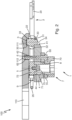
- FIG 2 is a schematic sectional view through the clamping device 1 from Figure 1 shown.
- the reference number 110 indicates a carrier of a container treatment device 100 that can rotate about an axis of rotation not shown here.
- the pivot axis 3 with its cylindrical pin section 30 is inserted into a correspondingly designed bore 111 of the carrier 110 and thus the form fit is formed transversely to the longitudinal direction 34.
- the pivot axis 3 is inserted into the bore 111 up to its longitudinal stop 33.
- the pivot axis 3 has a central section 32, starting from the longitudinal stop 33 that abuts the carrier 110, around which the Clamp arms 2 are each pivotably mounted with a hub bore 22.
- the middle section 32 extends to a further longitudinal shoulder 33 for striking the carrier plate 4.
- the pivot axis 3 has a fitting section 31 which is inserted into a fitting bore 41 of the carrier plate 4.
- the diameter of the central portion 32 is larger than that of the cylindrical pin portion 30 and that of the fitting portion 31, the previously described longitudinal shoulders 33 are present on both sides of the central portion 32.
- the fitting section 31 and the fitting bore 41 form a press fit so that the pivot axes 3 are fastened to the carrier plate 4.
- the fastening screw 6 is screwed into a corresponding threaded hole 112 provided in the carrier 110 by means of a threaded section 62.
- the fastening screw 6 which runs through a through hole 42 in the carrier plate 4
- the carrier plate 4 is supported on the carrier plate 4 by means of a head section 60, with a securing element 8, described in detail later, being arranged between the head section 60 and the carrier plate 4.
- the front side 50 and the stop 52 of the support bolts 5, as well as the longitudinal stops 33 of the pivot axes 3 are spaced apart from one another by a predetermined distance 9 in the longitudinal direction 34.
- the carrier plate 4 when screwed to the carrier 110 by means of the fastening screw 6, is also held at a distance 9 from the carrier 110.
- the fastening screw 6 is arranged between the pivot axes 3 and the support bolts 5.
- the pivot axes 3 are arranged on one side and the support bolts 5 on the other side.
- the tightening force generated by the fastening screw 6 is transmitted to the carrier 110 on both sides of the fastening screw 6 via the carrier plate 4 on the one side via the support bolts 5 and on the other side via the pivot axes 3.
- the fastening screw 6 is designed such that a predetermined number of five turns is necessary to attach the clamping device 1 or to release the clamping device 1.
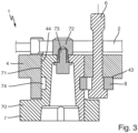
- Figure 3 shows a schematic detailed view of Figure 2 , in which the area of the control cam 7 and the fastening screw 6 is shown in detail, with the carrier 110 hidden.
- the control cam 7 has a shaft section 71, by means of which it is guided in the axial direction relative to the longitudinal direction 34 of the pivot axes 3 in a cam bore 44 of the carrier plate 4.
- the control cam 7 also has a radial groove 74.
- the securing element 8 engages in the radial groove 74 so that the control cam 7 is fixed in the axial direction relative to the carrier plate 4.
- the carrier plate 4 has a recess 43 through which the securing element 8 can be held in a manner as shown in Figure 3 is fixed in the locking position shown.
- the securing element 8 can be moved out of the securing position by pushing the securing element 8 over the stop 34.
- FIG 4 schematically shows a further detailed view of the clamping device 1 according to the Figures 1-3 shows.
- FIG. 5 is a schematic further detailed view of the clamping device 1 according to the Figures 1-4 in which the control cam 7 is shown in a state dismantled from the carrier plate 4.
- the main body 70 and the interaction element 72 can have a metal/plastic pairing or a plastic/metal pairing.
- both parts 70, 72 can be metal or Plastic, wherein the parts 70, 72 are then preferably formed in one piece.
- the control cam z can have a coating, in particular a friction coefficient-reducing coating, preferably made of a plastic, at least partially, preferably in the region of the interaction section 72, the shaft section 70 and/or an engagement region with a switch or a guide of the container treatment device 100.
- the clamping device 1 is designed to be mirror-symmetrical with respect to a longitudinal axis 10.
- the pivot axes 3 and the support bolts 5 are arranged on both sides of the longitudinal axis 10 and are each at the same distance from the longitudinal axis 10 as their respective opposite counterpart. The above description results in a symmetrical loading of the clamping device 1.
Landscapes
- Engineering & Computer Science (AREA)
- Mechanical Engineering (AREA)
- Clamps And Clips (AREA)
- Filling Of Jars Or Cans And Processes For Cleaning And Sealing Jars (AREA)
- Specific Conveyance Elements (AREA)
- Robotics (AREA)
Applications Claiming Priority (2)
| Application Number | Priority Date | Filing Date | Title |
|---|---|---|---|
| DE102019131587.5A DE102019131587A1 (de) | 2019-11-22 | 2019-11-22 | Klammervorrichtung zum Halten eines Behälters |
| EP20209312.6A EP3825265B1 (fr) | 2019-11-22 | 2020-11-23 | Dispositif de serrage permettant de maintenir un récipient |
Related Parent Applications (1)
| Application Number | Title | Priority Date | Filing Date |
|---|---|---|---|
| EP20209312.6A Division EP3825265B1 (fr) | 2019-11-22 | 2020-11-23 | Dispositif de serrage permettant de maintenir un récipient |
Publications (2)
| Publication Number | Publication Date |
|---|---|
| EP4393854A2 true EP4393854A2 (fr) | 2024-07-03 |
| EP4393854A3 EP4393854A3 (fr) | 2024-08-28 |
Family
ID=73544099
Family Applications (2)
| Application Number | Title | Priority Date | Filing Date |
|---|---|---|---|
| EP24176650.0A Pending EP4393854A3 (fr) | 2019-11-22 | 2020-11-23 | Dispositif de serrage pour maintenir un récipient |
| EP20209312.6A Active EP3825265B1 (fr) | 2019-11-22 | 2020-11-23 | Dispositif de serrage permettant de maintenir un récipient |
Family Applications After (1)
| Application Number | Title | Priority Date | Filing Date |
|---|---|---|---|
| EP20209312.6A Active EP3825265B1 (fr) | 2019-11-22 | 2020-11-23 | Dispositif de serrage permettant de maintenir un récipient |
Country Status (4)
| Country | Link |
|---|---|
| US (1) | US11802035B2 (fr) |
| EP (2) | EP4393854A3 (fr) |
| CN (1) | CN112830438B (fr) |
| DE (1) | DE102019131587A1 (fr) |
Families Citing this family (1)
| Publication number | Priority date | Publication date | Assignee | Title |
|---|---|---|---|---|
| DE102021131001A1 (de) * | 2021-11-25 | 2023-05-25 | Krones Aktiengesellschaft | Klammervorrichtung zum Halten eines Behälters |
Citations (1)
| Publication number | Priority date | Publication date | Assignee | Title |
|---|---|---|---|---|
| DE102015218204A1 (de) | 2015-09-22 | 2017-03-23 | Henkel Ag & Co. Kgaa | Hautkosmetikum |
Family Cites Families (15)
| Publication number | Priority date | Publication date | Assignee | Title |
|---|---|---|---|---|
| EP0795500B1 (fr) | 1996-03-13 | 2002-11-13 | Kronseder, Hermann, Dr.-Ing. E.h. | Roue à étoile pour récipients |
| ITRM20020147A1 (it) | 2002-03-18 | 2003-09-18 | Sipa Spa | Dispositivo di presa a pinza per bottiglie e simili. |
| DE202006018379U1 (de) * | 2006-12-05 | 2008-01-10 | Krones Ag | Greifer, insbesondere für Gefäße |
| DE502008001906D1 (de) | 2008-09-02 | 2011-01-05 | Tyrolon Schulnig Gmbh | Transportstern |
| IT1391818B1 (it) * | 2008-11-13 | 2012-01-27 | Mbf Spa | Apparecchiatura per il trasferimento di contenitori |
| DE102009038988B3 (de) * | 2009-08-31 | 2011-03-31 | Khs Gmbh | Greifer zum Halten von Gefäßen wie PET-Flaschen |
| DE102010009364B4 (de) * | 2010-02-25 | 2017-05-18 | Khs Gmbh | Flaschenklammer mit Sperre |
| DE102010052348A1 (de) * | 2010-11-25 | 2012-05-31 | Khs Gmbh | PET-Flaschen-Greifvorrichtung |
| DE102012011367A1 (de) * | 2012-06-11 | 2013-12-12 | Khs Gmbh | Greiferanordnung |
| DE102012218204A1 (de) * | 2012-10-05 | 2014-04-10 | Krones Ag | Klammergreifer für Behälter |
| US8672376B1 (en) * | 2012-11-16 | 2014-03-18 | Morrison Container Handling Solutions, Inc. | Gripping device |
| ES2531199T3 (es) * | 2013-02-20 | 2015-03-11 | Tyrolon Schulnig Gmbh | Brazo de agarre para recipientes y procedimiento para la producción de un brazo de agarre de este tipo |
| EP2769942B1 (fr) * | 2013-02-25 | 2016-09-14 | Tyrolon-Schulnig GmbH | Bras de préhension pour un dispositif de préhension ainsi que la machine pour transporter des récipients au moyen de ces bras de préhension |
| EP3397577B1 (fr) | 2017-01-10 | 2020-08-05 | Tyrolon-Schulnig GmbH | Bras de préhension pour contenants et dispositif de préhension comprenant des bras de préhension de ce type |
| DE102017108926B4 (de) * | 2017-04-26 | 2023-08-03 | Khs Gmbh | Vorrichtung zum Transportieren von Behältern |
-
2019
- 2019-11-22 DE DE102019131587.5A patent/DE102019131587A1/de active Pending
-
2020
- 2020-11-18 CN CN202011295260.8A patent/CN112830438B/zh active Active
- 2020-11-20 US US16/953,624 patent/US11802035B2/en active Active
- 2020-11-23 EP EP24176650.0A patent/EP4393854A3/fr active Pending
- 2020-11-23 EP EP20209312.6A patent/EP3825265B1/fr active Active
Patent Citations (1)
| Publication number | Priority date | Publication date | Assignee | Title |
|---|---|---|---|---|
| DE102015218204A1 (de) | 2015-09-22 | 2017-03-23 | Henkel Ag & Co. Kgaa | Hautkosmetikum |
Also Published As
| Publication number | Publication date |
|---|---|
| US20210154863A1 (en) | 2021-05-27 |
| DE102019131587A1 (de) | 2021-05-27 |
| EP3825265A1 (fr) | 2021-05-26 |
| EP3825265B1 (fr) | 2024-05-22 |
| EP4393854A3 (fr) | 2024-08-28 |
| US11802035B2 (en) | 2023-10-31 |
| CN112830438B (zh) | 2022-11-29 |
| CN112830438A (zh) | 2021-05-25 |
| EP3825265C0 (fr) | 2024-05-22 |
Similar Documents
| Publication | Publication Date | Title |
|---|---|---|
| EP2325502B1 (fr) | Agencement et procédé pour relier un accessoire avec une table d'opération | |
| DE68905723T2 (de) | Vorrichtung zum befestigen einer triebwerkaufhaengungsstange an luftfahrzeugen. | |
| DE102007037242B4 (de) | Befestigungseinrichtung mit Toleranzausgleich | |
| DE10043980C1 (de) | Vorrichtung zum Austauschen von Zahnriemenscheiben an Kraftfahrzeugmotoren | |
| DD284073A5 (de) | Spannsatz | |
| DE19945097A1 (de) | Spannmittel | |
| DE102007059148B4 (de) | Haltenocken für einen Drehverschluss | |
| AT516984B1 (de) | Vorrichtung zur Montage eines Möbelbeschlages | |
| EP0748421A1 (fr) | Systeme de serrage pourvu d'un goujon de serrage conique | |
| EP2241527B1 (fr) | Dispositif de raccordement | |
| EP3132146B1 (fr) | Dispositif de fixation | |
| EP3141639B1 (fr) | Dispositif de fixation pour element de peigne sur un peigne rond | |
| EP0275441B1 (fr) | Dispositif de serrage | |
| DE10056341A1 (de) | Vorrichtung zum Verzurren von Containern | |
| EP3825265B1 (fr) | Dispositif de serrage permettant de maintenir un récipient | |
| EP2602495B1 (fr) | Module de construction pour une transmission modulaire | |
| DE60038654T2 (de) | Klemmhalterung für Stütz- und Verbindungselemente | |
| EP3807012B1 (fr) | Centrifugeuse | |
| DE202018100571U1 (de) | Schraubwerkzeug | |
| DE3220743C2 (de) | Einrichtung zum Verzurren von Containern | |
| DE102019206750B4 (de) | Vorrichtung zum Ausgleichen von Toleranzen zwischen einem ersten Bauteil und einem zweiten Bauteil | |
| DE20212656U1 (de) | Haltebolzenanordnung | |
| DE69922444T2 (de) | Feder- Verriegelungsvorrichtung | |
| DE10148473A1 (de) | Kraftschlüssig selbstsichernde Mutter für eine Schraubverbindung | |
| DE102023103194A1 (de) | Verbindungselement zweier zueinander beabstandeter Bauteile mit Toleranzausgleichsfunktion sowie ein Installationsverfahren dafür |
Legal Events
| Date | Code | Title | Description |
|---|---|---|---|
| PUAI | Public reference made under article 153(3) epc to a published international application that has entered the european phase |
Free format text: ORIGINAL CODE: 0009012 |
|
| STAA | Information on the status of an ep patent application or granted ep patent |
Free format text: STATUS: THE APPLICATION HAS BEEN PUBLISHED |
|
| AC | Divisional application: reference to earlier application |
Ref document number: 3825265 Country of ref document: EP Kind code of ref document: P |
|
| AK | Designated contracting states |
Kind code of ref document: A2 Designated state(s): AL AT BE BG CH CY CZ DE DK EE ES FI FR GB GR HR HU IE IS IT LI LT LU LV MC MK MT NL NO PL PT RO RS SE SI SK SM TR |
|
| PUAL | Search report despatched |
Free format text: ORIGINAL CODE: 0009013 |
|
| AK | Designated contracting states |
Kind code of ref document: A3 Designated state(s): AL AT BE BG CH CY CZ DE DK EE ES FI FR GB GR HR HU IE IS IT LI LT LU LV MC MK MT NL NO PL PT RO RS SE SI SK SM TR |
|
| RIC1 | Information provided on ipc code assigned before grant |
Ipc: B65G 47/86 20060101AFI20240719BHEP |
|
| STAA | Information on the status of an ep patent application or granted ep patent |
Free format text: STATUS: REQUEST FOR EXAMINATION WAS MADE |
|
| 17P | Request for examination filed |
Effective date: 20250228 |
|
| GRAP | Despatch of communication of intention to grant a patent |
Free format text: ORIGINAL CODE: EPIDOSNIGR1 |
|
| STAA | Information on the status of an ep patent application or granted ep patent |
Free format text: STATUS: GRANT OF PATENT IS INTENDED |
|
| INTG | Intention to grant announced |
Effective date: 20250704 |
|
| GRAJ | Information related to disapproval of communication of intention to grant by the applicant or resumption of examination proceedings by the epo deleted |
Free format text: ORIGINAL CODE: EPIDOSDIGR1 |
|
| STAA | Information on the status of an ep patent application or granted ep patent |
Free format text: STATUS: REQUEST FOR EXAMINATION WAS MADE |
|
| INTC | Intention to grant announced (deleted) | ||
| GRAP | Despatch of communication of intention to grant a patent |
Free format text: ORIGINAL CODE: EPIDOSNIGR1 |
|
| STAA | Information on the status of an ep patent application or granted ep patent |
Free format text: STATUS: GRANT OF PATENT IS INTENDED |
|
| INTG | Intention to grant announced |
Effective date: 20251218 |
|
| GRAS | Grant fee paid |
Free format text: ORIGINAL CODE: EPIDOSNIGR3 |
|
| GRAJ | Information related to disapproval of communication of intention to grant by the applicant or resumption of examination proceedings by the epo deleted |
Free format text: ORIGINAL CODE: EPIDOSDIGR1 |
|
| GRAL | Information related to payment of fee for publishing/printing deleted |
Free format text: ORIGINAL CODE: EPIDOSDIGR3 |
|
| STAA | Information on the status of an ep patent application or granted ep patent |
Free format text: STATUS: REQUEST FOR EXAMINATION WAS MADE |