EP4394150A2 - Ensemble porte coupe-fumée pour former une porte coupe-fumée avec élément de fermeture pour fermer de manière étanche à la fumée l'évidement du cylindre de serrure - Google Patents
Ensemble porte coupe-fumée pour former une porte coupe-fumée avec élément de fermeture pour fermer de manière étanche à la fumée l'évidement du cylindre de serrure Download PDFInfo
- Publication number
- EP4394150A2 EP4394150A2 EP24176921.5A EP24176921A EP4394150A2 EP 4394150 A2 EP4394150 A2 EP 4394150A2 EP 24176921 A EP24176921 A EP 24176921A EP 4394150 A2 EP4394150 A2 EP 4394150A2
- Authority
- EP
- European Patent Office
- Prior art keywords
- smoke
- door leaf
- door
- base plate
- smoke protection
- Prior art date
- Legal status (The legal status is an assumption and is not a legal conclusion. Google has not performed a legal analysis and makes no representation as to the accuracy of the status listed.)
- Pending
Links
Images




Classifications
-
- E—FIXED CONSTRUCTIONS
- E06—DOORS, WINDOWS, SHUTTERS, OR ROLLER BLINDS IN GENERAL; LADDERS
- E06B—FIXED OR MOVABLE CLOSURES FOR OPENINGS IN BUILDINGS, VEHICLES, FENCES OR LIKE ENCLOSURES IN GENERAL, e.g. DOORS, WINDOWS, BLINDS, GATES
- E06B5/00—Doors, windows, or like closures for special purposes; Border constructions therefor
- E06B5/10—Doors, windows, or like closures for special purposes; Border constructions therefor for protection against air-raid or other war-like action; for other protective purposes
- E06B5/16—Fireproof doors or similar closures; Adaptations of fixed constructions therefor
-
- E—FIXED CONSTRUCTIONS
- E05—LOCKS; KEYS; WINDOW OR DOOR FITTINGS; SAFES
- E05B—LOCKS; ACCESSORIES THEREFOR; HANDCUFFS
- E05B15/00—Other details of locks; Parts for engagement by bolts of fastening devices
- E05B15/02—Striking-plates; Keepers; Bolt staples; Escutcheons
-
- E—FIXED CONSTRUCTIONS
- E05—LOCKS; KEYS; WINDOW OR DOOR FITTINGS; SAFES
- E05B—LOCKS; ACCESSORIES THEREFOR; HANDCUFFS
- E05B17/00—Accessories in connection with locks
- E05B17/0075—Insulating, e.g. for limiting heat transfer; Increasing fire-resistance of locks
-
- E—FIXED CONSTRUCTIONS
- E05—LOCKS; KEYS; WINDOW OR DOOR FITTINGS; SAFES
- E05B—LOCKS; ACCESSORIES THEREFOR; HANDCUFFS
- E05B63/00—Locks or fastenings with special structural characteristics
- E05B63/0043—Dummy or simulated locks; Cover elements without lock function
-
- E—FIXED CONSTRUCTIONS
- E06—DOORS, WINDOWS, SHUTTERS, OR ROLLER BLINDS IN GENERAL; LADDERS
- E06B—FIXED OR MOVABLE CLOSURES FOR OPENINGS IN BUILDINGS, VEHICLES, FENCES OR LIKE ENCLOSURES IN GENERAL, e.g. DOORS, WINDOWS, BLINDS, GATES
- E06B3/00—Window sashes, door leaves, or like elements for closing wall or like openings; Layout of fixed or moving closures, e.g. windows in wall or like openings; Features of rigidly-mounted outer frames relating to the mounting of wing frames
- E06B3/70—Door leaves
- E06B2003/7046—Door leaves with provisions for locks, hinges or other fittings
Definitions
- the flat cover elements for the door leaf are designed with a cover element contour such that the cover elements are completely covered by the base plate and/or a fitting and/or completely disappear in the base plate and/or in the fitting.
- the cover element hole pattern 14 in the flat cover element 10, as shown in Fig.1 The large cover plate 12 shown must be designed and implemented by providing cover element holes 16 so that the locking cylinder recess 20 can be closed smoke-tight by a sufficiently hole-free area in the flat cover element 10 and at the same time the base plate to be attached above the flat cover element 10 during assembly, which has base plate holes for screwing, can be screwed onto the door leaf 26 through cover element holes 16 in the flat cover element 10.
- a double-sided adhesive tape 22 is also glued to the large cover plate 12. It has a pull-off tab 24 protruding from the left edge and the right edge of the large cover plate 12, with the help of which the protective film on the double-sided adhesive tape 22 can be easily removed.
- Fig.1 further shows an alternative arrangement of the double-sided adhesive tape 22, in which the double-sided adhesive tape 22 with the protruding pull tab 24 is arranged rotated by 90 °.
- the double-sided adhesive tape 22 is an optional feature of the flat cover element 10, such as the large cover plate 12. It serves as an assembly aid and should advantageously be able to be removed without leaving any residue.
- the large cover plate 12 can be fixed precisely to the surface of the door leaf 26 before the base plate 56 is screwed onto the large cover plate 12 and the door leaf 26 to form a sandwich structure. By screwing it on, the large cover plate 12 is pressed by the base plate against the surface of the door leaf 26.
- the smoke-tight seal which must withstand a smoke gas temperature of up to 200 °C at a load pressure of up to 50 Pa after 30 minutes, is essentially achieved by this pressing of the large cover plate 12, but can be further reinforced by the adhesive connection between the large cover plate 12 and the door leaf 26.
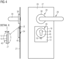
- the handle base plate 56 arranged under the short plate 32 is screwed to the cover plate 27 of the door leaf 26 with two screws 34 through two base plate holes 58 in the base plate 56.
- the large cover plate 12 is fixed in a sandwich structure between the screwed base plate 56 and the door leaf 26.
- the screwed base plate 56 presses the large cover plate 12 against the door leaf 26 or the cover plate 27 and ensures the smoke-tight closure of the cylinder cutout 44 and the locking cylinder recess 20.
- the base plate 56 of the cylinder rosette 40 has two screw holes (not visible) to the left and right of the cylinder hole 36 in the cylinder rosette 40, through which the base plate 56 is screwed to the cover plate 27.
- the same flat cover element 10 or large cover plate 12 can be used for the initial assembly of the smoke protection door using the smoke protection door kit to produce the smoke-tight closure of the locking cylinder recess 20, because the flat cover element 10 has a cover element hole pattern 14 that is compatible with both base plate hole patterns.
- Fig.5 shows a second embodiment of a flat cover element 10 in the form of a small cover plate 42.
- the small cover plate 12 has, as a cover element contour 18, two opposing curved edges in the form of circular arcs 50 of equal size, which are connected to one another by two predominantly parallel and overall mirror-image straight edges 52.
- Semicircular cover element recesses 54 are provided in the middle of the parallel straight edges.
- the drawing of the small cover plate 42 has a dashed line in the shape of an elongated circle in the central position. This area corresponds to the cylinder cutout 44 which is formed in the cover plate of the door leaf 26 to accommodate the locking cylinder and which, when installed, is closed off smoke-tight by the small cover plate 42.
- the base plate 56 and the small cover plate 42 By screwing the base plate 56 and the small cover plate 42 over the cover plate cylinder cutout 44, the locking cylinder recess 20 in the door leaf 26 is closed off smoke-tight without a locking cylinder or a dummy cylinder having to be inserted into the recess.
- the double-sided adhesive tape 22 is formed here without any protruding release film.
- Fig.5 Below the front view of the small cover plate 42 is a perspective view of the small cover plate 42.
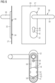
- Fig.6 illustrates the use of the small cover plate 42 according to Fig.5 for a smoke protection door with short plate handle set.
- the use of the small cover plate 42 is the only and essential difference to the Fig.3 All other components and reference symbols correspond to Fig.3 so that in this respect Fig.3 can be referred to.
- the upper illustration shows the front view and the side view of the door leaf in the area of the handle, the lower illustration shows a rear view of the door leaf in the area of the handle without the box sheet that is actually present.
- the small cover plate 42 has such dimensions that it is completely covered by the short plate 32. This gives an aesthetic overall impression while maintaining a good smoke-tight closure of the cylinder cutout 44 and the locking cylinder recess 20.
- the rear view of the door leaf 26 illustrates the precise arrangement of the small cover plate 42 between the base plate 56 and the door leaf 26.
- the small cover plate 42 can be fitted with its parallel vertical edges exactly into the short plate 32 with its vertical parallel edges. It lies flat on the base plate 56. Due to the arrangement of the two base plate holes 58 in the base plate 52 below and above the small cover plate 42, the cover element recesses 54 in the small cover plate 42 are inoperative. Due to the sufficiently large distance between the base plate holes 58 in the base plate 52 and the cylinder hole 36 in the base plate 52 and the sufficiently small dimensions of the small cover plate 42, the screwing of the base plate 56 to the door leaf 26 is not hindered by the small cover plate 42. Thus, in the small cover plate 42, no further cover element holes 16 are provided, as in the embodiment according to Fig.1 and Fig.3 required are.
- the side view of the embodiment according to Fig.6 shows that the small cover plate 42 has such dimensions that it completely disappears in the recess of the short shield 32. Unlike in Fig.3 The small cover plate 42 does not add any bulk at all.
- the small cover plate 42 For the installation of the small cover plate 42, it is advantageous to provide the small cover plate with a double-sided adhesive tape 22 without a pull-off tab. After removing the protective film of the double-sided adhesive tape 22, the small cover plate 42 is glued either over the cylinder cutout 44 onto the door leaf 26 or onto the base plate 56.
- Fig.7 illustrates the use of the small cover plate 42 according to Fig.5 for a smoke protection door with rosette fitting.
- the use of the small cover plate 42 instead of the large cover plate 12 is the only and essential difference to the Fig.4 Since all other components and reference numerals are Fig.4 can be referred to the description of the embodiment according to Fig.4 can be referred to.
- the upper illustration in Fig.7 shows the front view and the side view of the door leaf 26 in the area of the handle.
- the lower illustration shows a rear view of the door leaf 26 in the area of the handle without the box sheet that is actually present.
- FIG.7 shows that the small cover plate 42 has such dimensions that it is completely covered by the cylinder rosette 40. This gives an overall aesthetic impression while maintaining a good smoke-tight closure of the cylinder cutout 44 and the locking cylinder recess 20.
- the rear view of the door leaf 26 illustrates the precise arrangement of the small cover plate 42 between the base plate 56 of the cylinder rosette 40 and the door leaf 26.
- the small cover plate 42 with its basic shape derived from a circle, fits exactly into the recess of the circular and slightly larger cylinder rosette 40. It lies flat on the circular base plate 56.
- the two base plate holes 58 are arranged in the base plate 56 to the left and right of the invisible cylinder hole 36.
- the recesses 54 in the small cover plate 42 enable the base plate 56 to be screwed to the door leaf 26 without hindrance.
- Cover element holes 16 are not required due to the cover element contour 18. This represents a significant difference to the embodiment according to Fig.1 and Fig.4 in which the large cover plate 12 has a cover element hole pattern 14 which enables the base plate to be screwed to the door leaf 26.
- the side view of the embodiment according to Fig.7 shows that the small cover plate 42 has such dimensions that it completely disappears in the recess of the cylinder rosette 40. Unlike in Fig.5 the small cover plate 42 does not add any bulk at all.
- the hole pattern of the base plates 56 and their contour differ considerably in a short plate 32 and a rosette fitting consisting of a handle rosette 38 and a cylinder rosette 40, the same small cover plate 42 can be used to create the smoke-tight closure of the locking cylinder recess 20 during the initial assembly of the smoke protection door using the smoke protection door kit, because the small cover plate 42 has the cover element contour 18 required for this.
- cover element contour 18 By further refining the cover element contour 18 and, if necessary, providing a more universal hole pattern in the flat cover element 10, it is possible to cover the handle hole pattern of other handle sets, such as H8-5. With appropriate design, many different smoke protection door assemblies with different handle sets and different handle hole patterns can be equipped with a single flat cover element 10.
Landscapes
- Engineering & Computer Science (AREA)
- Structural Engineering (AREA)
- Physics & Mathematics (AREA)
- Thermal Sciences (AREA)
- Civil Engineering (AREA)
- Special Wing (AREA)
- Specific Sealing Or Ventilating Devices For Doors And Windows (AREA)
- Casings For Electric Apparatus (AREA)
Applications Claiming Priority (2)
| Application Number | Priority Date | Filing Date | Title |
|---|---|---|---|
| DE102018132985.7A DE102018132985A1 (de) | 2018-12-19 | 2018-12-19 | Rauchschutztür-Bausatz zum Bilden einer Rauchschutztür mit Verschlusselement zum rauchdichten Verschließen der Schließzylinderaussparung |
| EP19216440.8A EP3670812B1 (fr) | 2018-12-19 | 2019-12-16 | Ensemble de porte de protection contre la fumée permettant de fabriquer une porte de protection contre la fumée pourvue d'élément de fermeture permettant de fermer de manière étanche la fente du cylindre de serrure |
Related Parent Applications (2)
| Application Number | Title | Priority Date | Filing Date |
|---|---|---|---|
| EP19216440.8A Division-Into EP3670812B1 (fr) | 2018-12-19 | 2019-12-16 | Ensemble de porte de protection contre la fumée permettant de fabriquer une porte de protection contre la fumée pourvue d'élément de fermeture permettant de fermer de manière étanche la fente du cylindre de serrure |
| EP19216440.8A Division EP3670812B1 (fr) | 2018-12-19 | 2019-12-16 | Ensemble de porte de protection contre la fumée permettant de fabriquer une porte de protection contre la fumée pourvue d'élément de fermeture permettant de fermer de manière étanche la fente du cylindre de serrure |
Publications (2)
| Publication Number | Publication Date |
|---|---|
| EP4394150A2 true EP4394150A2 (fr) | 2024-07-03 |
| EP4394150A3 EP4394150A3 (fr) | 2024-09-04 |
Family
ID=68917542
Family Applications (2)
| Application Number | Title | Priority Date | Filing Date |
|---|---|---|---|
| EP24176921.5A Pending EP4394150A3 (fr) | 2018-12-19 | 2019-12-16 | Ensemble porte coupe-fumée pour former une porte coupe-fumée avec élément de fermeture pour fermer de manière étanche à la fumée l'évidement du cylindre de serrure |
| EP19216440.8A Active EP3670812B1 (fr) | 2018-12-19 | 2019-12-16 | Ensemble de porte de protection contre la fumée permettant de fabriquer une porte de protection contre la fumée pourvue d'élément de fermeture permettant de fermer de manière étanche la fente du cylindre de serrure |
Family Applications After (1)
| Application Number | Title | Priority Date | Filing Date |
|---|---|---|---|
| EP19216440.8A Active EP3670812B1 (fr) | 2018-12-19 | 2019-12-16 | Ensemble de porte de protection contre la fumée permettant de fabriquer une porte de protection contre la fumée pourvue d'élément de fermeture permettant de fermer de manière étanche la fente du cylindre de serrure |
Country Status (4)
| Country | Link |
|---|---|
| EP (2) | EP4394150A3 (fr) |
| DE (1) | DE102018132985A1 (fr) |
| ES (1) | ES2987283T3 (fr) |
| PL (1) | PL3670812T3 (fr) |
Families Citing this family (1)
| Publication number | Priority date | Publication date | Assignee | Title |
|---|---|---|---|---|
| DE102024107606A1 (de) | 2024-03-18 | 2025-09-18 | Eco Schulte Gmbh & Co. Kg | Abdichtelement für einen Beschlag zum flamm- und rauchgasdichten Verschließen einer Schließzylinderausnehmung des Beschlags |
Family Cites Families (8)
| Publication number | Priority date | Publication date | Assignee | Title |
|---|---|---|---|---|
| DE2607248A1 (de) * | 1975-02-26 | 1976-09-09 | Horst Peter Dipl Ing Seiffarth | Anordnung bei einer feuerhemmenden tuere o.dgl. durchgangsoeffnung |
| DE8102621U1 (de) * | 1981-02-03 | 1981-07-09 | Echt & Co, Nachf. Schulte Kg, 5750 Menden | "tuerschild fuer eine feuerschutztuer o.dgl. |
| DE3530876A1 (de) * | 1984-10-19 | 1986-04-24 | Lothar Laflör GmbH & Co, 5620 Velbert | Tuerschloss fuer feuerhemmende tueren |
| DE8700069U1 (de) * | 1987-01-02 | 1988-04-28 | Hörmann KG Freisen, 6699 Freisen | Unterschild einer Türdrückergarnitur für Feuerschutztüren |
| DE8803208U1 (de) * | 1988-03-10 | 1988-04-28 | Paul Schmitz GmbH, 5200 Siegburg | Stahltür |
| CA2177550A1 (fr) * | 1995-05-31 | 1996-12-01 | Khurshid A. Qureshi | Cage modulaire de ressort de rappel, pour poignee de porte |
| FR2807094B1 (fr) * | 2000-03-31 | 2003-07-04 | Claude Vlaeminck | Porte coupe-feu |
| DE102007019883A1 (de) * | 2007-04-27 | 2008-11-06 | Fa. Meusel + Beck | Zier- Steckverschluß für Schlüssellöcher |
-
2018
- 2018-12-19 DE DE102018132985.7A patent/DE102018132985A1/de active Pending
-
2019
- 2019-12-16 PL PL19216440.8T patent/PL3670812T3/pl unknown
- 2019-12-16 ES ES19216440T patent/ES2987283T3/es active Active
- 2019-12-16 EP EP24176921.5A patent/EP4394150A3/fr active Pending
- 2019-12-16 EP EP19216440.8A patent/EP3670812B1/fr active Active
Also Published As
| Publication number | Publication date |
|---|---|
| EP3670812A1 (fr) | 2020-06-24 |
| EP3670812C0 (fr) | 2024-08-14 |
| EP3670812B1 (fr) | 2024-08-14 |
| DE102018132985A1 (de) | 2020-06-25 |
| EP4394150A3 (fr) | 2024-09-04 |
| ES2987283T3 (es) | 2024-11-14 |
| PL3670812T3 (pl) | 2024-12-16 |
Similar Documents
| Publication | Publication Date | Title |
|---|---|---|
| DE2850125A1 (de) | Tuer | |
| DE102020131834A1 (de) | Tür, insbesondere Haustür und Verfahren zur Herstellung eines Türflügels für eine solche Tür | |
| EP1784549B1 (fr) | Chambre de securite | |
| DE19608529C2 (de) | Revisionsabdeckung | |
| EP3670812B1 (fr) | Ensemble de porte de protection contre la fumée permettant de fabriquer une porte de protection contre la fumée pourvue d'élément de fermeture permettant de fermer de manière étanche la fente du cylindre de serrure | |
| EP0078905B1 (fr) | Huisserie d'habillage pour le revêtement d'une ouverture dans une paroi pour une porte ou similaire | |
| EP2372069B1 (fr) | Dormant pare-feu en bois | |
| EP3342970A1 (fr) | Dispositif de garniture arrière ainsi que huisserie enveloppante associée | |
| EP2114200B1 (fr) | Pupitre de commande | |
| DE102018114378B4 (de) | Anordnung zur Sicherung von nach innen zu öffnenden Fenstern und Türen gegen Einbrüche | |
| EP4375472A1 (fr) | Porte, notamment porte de maison, et procédé de fabrication d'un battant de porte pour une telle porte | |
| DE19937835A1 (de) | Feuerschutzsystem | |
| EP1944429A1 (fr) | Porte de visite | |
| DE102013101649A1 (de) | Bauteilanordnung, Profileinheit und Verfahren zum Dämmen einer Einbaueinheit | |
| DE2406562A1 (de) | Feuerhemmende tuer | |
| DE102005001622A1 (de) | Zargenvorrichtung für Öffnungen in Wänden | |
| DE102004040749B4 (de) | Rauchschutzabschlusssystem | |
| EP1491702A1 (fr) | Trappe de visite | |
| DE19838458C2 (de) | Nachrüstzarge für einen Türrahmen und ein Türblatt | |
| DE202006018641U1 (de) | Brandschutztürsystem | |
| DE202016100569U1 (de) | Modularer Wandeinsatz zur Aufnahme eines Klimatisierungsgerätes | |
| EP3789577A1 (fr) | Porte coupe-feu, battant de porte, cadre, procédé de fabrication de la porte coupe-feu | |
| DE202006004425U1 (de) | Rahmenbaugruppe | |
| DE102019005882A1 (de) | Verdeckt liegendes Scharnier für eine Tür oder ein Fenster und damit ausgestattete Tür oder Fenster und Verfahren für die Montage eines festen Fenster- oder Türrahmens | |
| DE102014005329A1 (de) | Fassadensystem |
Legal Events
| Date | Code | Title | Description |
|---|---|---|---|
| PUAI | Public reference made under article 153(3) epc to a published international application that has entered the european phase |
Free format text: ORIGINAL CODE: 0009012 |
|
| STAA | Information on the status of an ep patent application or granted ep patent |
Free format text: STATUS: REQUEST FOR EXAMINATION WAS MADE |
|
| 17P | Request for examination filed |
Effective date: 20240521 |
|
| AC | Divisional application: reference to earlier application |
Ref document number: 3670812 Country of ref document: EP Kind code of ref document: P |
|
| AK | Designated contracting states |
Kind code of ref document: A2 Designated state(s): AL AT BE BG CH CY CZ DE DK EE ES FI FR GB GR HR HU IE IS IT LI LT LU LV MC MK MT NL NO PL PT RO RS SE SI SK SM TR |
|
| REG | Reference to a national code |
Ref country code: DE Ref legal event code: R079 Free format text: PREVIOUS MAIN CLASS: E05B0015020000 Ipc: E06B0005160000 |
|
| PUAL | Search report despatched |
Free format text: ORIGINAL CODE: 0009013 |
|
| AK | Designated contracting states |
Kind code of ref document: A3 Designated state(s): AL AT BE BG CH CY CZ DE DK EE ES FI FR GB GR HR HU IE IS IT LI LT LU LV MC MK MT NL NO PL PT RO RS SE SI SK SM TR |
|
| RIC1 | Information provided on ipc code assigned before grant |
Ipc: E05B 15/02 20060101ALI20240801BHEP Ipc: E06B 3/70 20060101ALI20240801BHEP Ipc: E05B 63/00 20060101ALI20240801BHEP Ipc: E05B 17/00 20060101ALI20240801BHEP Ipc: E06B 5/16 20060101AFI20240801BHEP |