EP4394432A1 - Utilisation de protocoles de nettoyage pour surveiller des défauts associés à des dispositifs de détection et de télémétrie par la lumière (lidar) - Google Patents
Utilisation de protocoles de nettoyage pour surveiller des défauts associés à des dispositifs de détection et de télémétrie par la lumière (lidar) Download PDFInfo
- Publication number
- EP4394432A1 EP4394432A1 EP23219177.5A EP23219177A EP4394432A1 EP 4394432 A1 EP4394432 A1 EP 4394432A1 EP 23219177 A EP23219177 A EP 23219177A EP 4394432 A1 EP4394432 A1 EP 4394432A1
- Authority
- EP
- European Patent Office
- Prior art keywords
- vehicle
- light
- cleaning
- lidar
- defects
- Prior art date
- Legal status (The legal status is an assumption and is not a legal conclusion. Google has not performed a legal analysis and makes no representation as to the accuracy of the status listed.)
- Pending
Links
Images










Classifications
-
- G—PHYSICS
- G01—MEASURING; TESTING
- G01S—RADIO DIRECTION-FINDING; RADIO NAVIGATION; DETERMINING DISTANCE OR VELOCITY BY USE OF RADIO WAVES; LOCATING OR PRESENCE-DETECTING BY USE OF THE REFLECTION OR RERADIATION OF RADIO WAVES; ANALOGOUS ARRANGEMENTS USING OTHER WAVES
- G01S7/00—Details of systems according to groups G01S13/00, G01S15/00, G01S17/00
- G01S7/48—Details of systems according to groups G01S13/00, G01S15/00, G01S17/00 of systems according to group G01S17/00
- G01S7/497—Means for monitoring or calibrating
-
- B—PERFORMING OPERATIONS; TRANSPORTING
- B08—CLEANING
- B08B—CLEANING IN GENERAL; PREVENTION OF FOULING IN GENERAL
- B08B1/00—Cleaning by methods involving the use of tools
- B08B1/10—Cleaning by methods involving the use of tools characterised by the type of cleaning tool
- B08B1/16—Rigid blades, e.g. scrapers; Flexible blades, e.g. wipers
- B08B1/165—Scrapers
-
- B—PERFORMING OPERATIONS; TRANSPORTING
- B08—CLEANING
- B08B—CLEANING IN GENERAL; PREVENTION OF FOULING IN GENERAL
- B08B13/00—Accessories or details of general applicability for machines or apparatus for cleaning
-
- B—PERFORMING OPERATIONS; TRANSPORTING
- B08—CLEANING
- B08B—CLEANING IN GENERAL; PREVENTION OF FOULING IN GENERAL
- B08B3/00—Cleaning by methods involving the use or presence of liquid or steam
- B08B3/02—Cleaning by the force of jets or sprays
-
- B—PERFORMING OPERATIONS; TRANSPORTING
- B08—CLEANING
- B08B—CLEANING IN GENERAL; PREVENTION OF FOULING IN GENERAL
- B08B5/00—Cleaning by methods involving the use of air flow or gas flow
- B08B5/02—Cleaning by the force of jets, e.g. blowing-out cavities
-
- B—PERFORMING OPERATIONS; TRANSPORTING
- B08—CLEANING
- B08B—CLEANING IN GENERAL; PREVENTION OF FOULING IN GENERAL
- B08B7/00—Cleaning by methods not provided for in a single other subclass or a single group in this subclass
- B08B7/04—Cleaning by methods not provided for in a single other subclass or a single group in this subclass by a combination of operations
-
- B—PERFORMING OPERATIONS; TRANSPORTING
- B60—VEHICLES IN GENERAL
- B60S—SERVICING, CLEANING, REPAIRING, SUPPORTING, LIFTING, OR MANOEUVRING OF VEHICLES, NOT OTHERWISE PROVIDED FOR
- B60S1/00—Cleaning of vehicles
- B60S1/02—Cleaning windscreens, windows or optical devices
- B60S1/56—Cleaning windscreens, windows or optical devices specially adapted for cleaning other parts or devices than front windows or windscreens
-
- G—PHYSICS
- G01—MEASURING; TESTING
- G01S—RADIO DIRECTION-FINDING; RADIO NAVIGATION; DETERMINING DISTANCE OR VELOCITY BY USE OF RADIO WAVES; LOCATING OR PRESENCE-DETECTING BY USE OF THE REFLECTION OR RERADIATION OF RADIO WAVES; ANALOGOUS ARRANGEMENTS USING OTHER WAVES
- G01S13/00—Systems using the reflection or reradiation of radio waves, e.g. radar systems; Analogous systems using reflection or reradiation of waves whose nature or wavelength is irrelevant or unspecified
- G01S13/86—Combinations of radar systems with non-radar systems, e.g. sonar, direction finder
- G01S13/865—Combination of radar systems with lidar systems
-
- G—PHYSICS
- G01—MEASURING; TESTING
- G01S—RADIO DIRECTION-FINDING; RADIO NAVIGATION; DETERMINING DISTANCE OR VELOCITY BY USE OF RADIO WAVES; LOCATING OR PRESENCE-DETECTING BY USE OF THE REFLECTION OR RERADIATION OF RADIO WAVES; ANALOGOUS ARRANGEMENTS USING OTHER WAVES
- G01S13/00—Systems using the reflection or reradiation of radio waves, e.g. radar systems; Analogous systems using reflection or reradiation of waves whose nature or wavelength is irrelevant or unspecified
- G01S13/86—Combinations of radar systems with non-radar systems, e.g. sonar, direction finder
- G01S13/867—Combination of radar systems with cameras
-
- G—PHYSICS
- G01—MEASURING; TESTING
- G01S—RADIO DIRECTION-FINDING; RADIO NAVIGATION; DETERMINING DISTANCE OR VELOCITY BY USE OF RADIO WAVES; LOCATING OR PRESENCE-DETECTING BY USE OF THE REFLECTION OR RERADIATION OF RADIO WAVES; ANALOGOUS ARRANGEMENTS USING OTHER WAVES
- G01S17/00—Systems using the reflection or reradiation of electromagnetic waves other than radio waves, e.g. lidar systems
- G01S17/02—Systems using the reflection of electromagnetic waves other than radio waves
- G01S17/06—Systems determining position data of a target
- G01S17/08—Systems determining position data of a target for measuring distance only
- G01S17/10—Systems determining position data of a target for measuring distance only using transmission of interrupted, pulse-modulated waves
-
- G—PHYSICS
- G01—MEASURING; TESTING
- G01S—RADIO DIRECTION-FINDING; RADIO NAVIGATION; DETERMINING DISTANCE OR VELOCITY BY USE OF RADIO WAVES; LOCATING OR PRESENCE-DETECTING BY USE OF THE REFLECTION OR RERADIATION OF RADIO WAVES; ANALOGOUS ARRANGEMENTS USING OTHER WAVES
- G01S17/00—Systems using the reflection or reradiation of electromagnetic waves other than radio waves, e.g. lidar systems
- G01S17/02—Systems using the reflection of electromagnetic waves other than radio waves
- G01S17/06—Systems determining position data of a target
- G01S17/42—Simultaneous measurement of distance and other co-ordinates
-
- G—PHYSICS
- G01—MEASURING; TESTING
- G01S—RADIO DIRECTION-FINDING; RADIO NAVIGATION; DETERMINING DISTANCE OR VELOCITY BY USE OF RADIO WAVES; LOCATING OR PRESENCE-DETECTING BY USE OF THE REFLECTION OR RERADIATION OF RADIO WAVES; ANALOGOUS ARRANGEMENTS USING OTHER WAVES
- G01S17/00—Systems using the reflection or reradiation of electromagnetic waves other than radio waves, e.g. lidar systems
- G01S17/02—Systems using the reflection of electromagnetic waves other than radio waves
- G01S17/50—Systems of measurement based on relative movement of target
- G01S17/58—Velocity or trajectory determination systems; Sense-of-movement determination systems
-
- G—PHYSICS
- G01—MEASURING; TESTING
- G01S—RADIO DIRECTION-FINDING; RADIO NAVIGATION; DETERMINING DISTANCE OR VELOCITY BY USE OF RADIO WAVES; LOCATING OR PRESENCE-DETECTING BY USE OF THE REFLECTION OR RERADIATION OF RADIO WAVES; ANALOGOUS ARRANGEMENTS USING OTHER WAVES
- G01S17/00—Systems using the reflection or reradiation of electromagnetic waves other than radio waves, e.g. lidar systems
- G01S17/86—Combinations of lidar systems with systems other than lidar, radar or sonar, e.g. with direction finders
-
- G—PHYSICS
- G01—MEASURING; TESTING
- G01S—RADIO DIRECTION-FINDING; RADIO NAVIGATION; DETERMINING DISTANCE OR VELOCITY BY USE OF RADIO WAVES; LOCATING OR PRESENCE-DETECTING BY USE OF THE REFLECTION OR RERADIATION OF RADIO WAVES; ANALOGOUS ARRANGEMENTS USING OTHER WAVES
- G01S17/00—Systems using the reflection or reradiation of electromagnetic waves other than radio waves, e.g. lidar systems
- G01S17/88—Lidar systems specially adapted for specific applications
- G01S17/89—Lidar systems specially adapted for specific applications for mapping or imaging
- G01S17/894—Three-dimensional [3D] imaging with simultaneous measurement of time-of-flight at a two-dimensional [2D] array of receiver pixels, e.g. time-of-flight cameras or flash lidar
-
- G—PHYSICS
- G01—MEASURING; TESTING
- G01S—RADIO DIRECTION-FINDING; RADIO NAVIGATION; DETERMINING DISTANCE OR VELOCITY BY USE OF RADIO WAVES; LOCATING OR PRESENCE-DETECTING BY USE OF THE REFLECTION OR RERADIATION OF RADIO WAVES; ANALOGOUS ARRANGEMENTS USING OTHER WAVES
- G01S17/00—Systems using the reflection or reradiation of electromagnetic waves other than radio waves, e.g. lidar systems
- G01S17/88—Lidar systems specially adapted for specific applications
- G01S17/93—Lidar systems specially adapted for specific applications for anti-collision purposes
- G01S17/931—Lidar systems specially adapted for specific applications for anti-collision purposes of land vehicles
-
- G—PHYSICS
- G01—MEASURING; TESTING
- G01S—RADIO DIRECTION-FINDING; RADIO NAVIGATION; DETERMINING DISTANCE OR VELOCITY BY USE OF RADIO WAVES; LOCATING OR PRESENCE-DETECTING BY USE OF THE REFLECTION OR RERADIATION OF RADIO WAVES; ANALOGOUS ARRANGEMENTS USING OTHER WAVES
- G01S7/00—Details of systems according to groups G01S13/00, G01S15/00, G01S17/00
- G01S7/003—Transmission of data between radar, sonar or lidar systems and remote stations
-
- G—PHYSICS
- G01—MEASURING; TESTING
- G01S—RADIO DIRECTION-FINDING; RADIO NAVIGATION; DETERMINING DISTANCE OR VELOCITY BY USE OF RADIO WAVES; LOCATING OR PRESENCE-DETECTING BY USE OF THE REFLECTION OR RERADIATION OF RADIO WAVES; ANALOGOUS ARRANGEMENTS USING OTHER WAVES
- G01S7/00—Details of systems according to groups G01S13/00, G01S15/00, G01S17/00
- G01S7/48—Details of systems according to groups G01S13/00, G01S15/00, G01S17/00 of systems according to group G01S17/00
- G01S7/481—Constructional features, e.g. arrangements of optical elements
- G01S7/4811—Constructional features, e.g. arrangements of optical elements common to transmitter and receiver
- G01S7/4813—Housing arrangements
-
- G—PHYSICS
- G01—MEASURING; TESTING
- G01S—RADIO DIRECTION-FINDING; RADIO NAVIGATION; DETERMINING DISTANCE OR VELOCITY BY USE OF RADIO WAVES; LOCATING OR PRESENCE-DETECTING BY USE OF THE REFLECTION OR RERADIATION OF RADIO WAVES; ANALOGOUS ARRANGEMENTS USING OTHER WAVES
- G01S7/00—Details of systems according to groups G01S13/00, G01S15/00, G01S17/00
- G01S7/48—Details of systems according to groups G01S13/00, G01S15/00, G01S17/00 of systems according to group G01S17/00
- G01S7/481—Constructional features, e.g. arrangements of optical elements
- G01S7/4814—Constructional features, e.g. arrangements of optical elements of transmitters alone
- G01S7/4815—Constructional features, e.g. arrangements of optical elements of transmitters alone using multiple transmitters
-
- G—PHYSICS
- G01—MEASURING; TESTING
- G01S—RADIO DIRECTION-FINDING; RADIO NAVIGATION; DETERMINING DISTANCE OR VELOCITY BY USE OF RADIO WAVES; LOCATING OR PRESENCE-DETECTING BY USE OF THE REFLECTION OR RERADIATION OF RADIO WAVES; ANALOGOUS ARRANGEMENTS USING OTHER WAVES
- G01S7/00—Details of systems according to groups G01S13/00, G01S15/00, G01S17/00
- G01S7/48—Details of systems according to groups G01S13/00, G01S15/00, G01S17/00 of systems according to group G01S17/00
- G01S7/481—Constructional features, e.g. arrangements of optical elements
- G01S7/4816—Constructional features, e.g. arrangements of optical elements of receivers alone
-
- G—PHYSICS
- G01—MEASURING; TESTING
- G01S—RADIO DIRECTION-FINDING; RADIO NAVIGATION; DETERMINING DISTANCE OR VELOCITY BY USE OF RADIO WAVES; LOCATING OR PRESENCE-DETECTING BY USE OF THE REFLECTION OR RERADIATION OF RADIO WAVES; ANALOGOUS ARRANGEMENTS USING OTHER WAVES
- G01S7/00—Details of systems according to groups G01S13/00, G01S15/00, G01S17/00
- G01S7/48—Details of systems according to groups G01S13/00, G01S15/00, G01S17/00 of systems according to group G01S17/00
- G01S7/481—Constructional features, e.g. arrangements of optical elements
- G01S7/4817—Constructional features, e.g. arrangements of optical elements relating to scanning
-
- G—PHYSICS
- G01—MEASURING; TESTING
- G01S—RADIO DIRECTION-FINDING; RADIO NAVIGATION; DETERMINING DISTANCE OR VELOCITY BY USE OF RADIO WAVES; LOCATING OR PRESENCE-DETECTING BY USE OF THE REFLECTION OR RERADIATION OF RADIO WAVES; ANALOGOUS ARRANGEMENTS USING OTHER WAVES
- G01S7/00—Details of systems according to groups G01S13/00, G01S15/00, G01S17/00
- G01S7/48—Details of systems according to groups G01S13/00, G01S15/00, G01S17/00 of systems according to group G01S17/00
- G01S7/483—Details of pulse systems
- G01S7/486—Receivers
- G01S7/4861—Circuits for detection, sampling, integration or read-out
- G01S7/4863—Detector arrays, e.g. charge-transfer gates
-
- G—PHYSICS
- G02—OPTICS
- G02B—OPTICAL ELEMENTS, SYSTEMS OR APPARATUS
- G02B27/00—Optical systems or apparatus not provided for by any of the groups G02B1/00 - G02B26/00, G02B30/00
- G02B27/0006—Optical systems or apparatus not provided for by any of the groups G02B1/00 - G02B26/00, G02B30/00 with means to keep optical surfaces clean, e.g. by preventing or removing dirt, stains, contamination, condensation
-
- B—PERFORMING OPERATIONS; TRANSPORTING
- B60—VEHICLES IN GENERAL
- B60S—SERVICING, CLEANING, REPAIRING, SUPPORTING, LIFTING, OR MANOEUVRING OF VEHICLES, NOT OTHERWISE PROVIDED FOR
- B60S1/00—Cleaning of vehicles
- B60S1/02—Cleaning windscreens, windows or optical devices
- B60S1/46—Cleaning windscreens, windows or optical devices using liquid; Windscreen washers
- B60S1/48—Liquid supply therefor
- B60S1/481—Liquid supply therefor the operation of at least part of the liquid supply being controlled by electric means
- B60S1/485—Liquid supply therefor the operation of at least part of the liquid supply being controlled by electric means including control systems responsive to external conditions, e.g. by detection of moisture, dirt or the like
-
- G—PHYSICS
- G01—MEASURING; TESTING
- G01S—RADIO DIRECTION-FINDING; RADIO NAVIGATION; DETERMINING DISTANCE OR VELOCITY BY USE OF RADIO WAVES; LOCATING OR PRESENCE-DETECTING BY USE OF THE REFLECTION OR RERADIATION OF RADIO WAVES; ANALOGOUS ARRANGEMENTS USING OTHER WAVES
- G01S7/00—Details of systems according to groups G01S13/00, G01S15/00, G01S17/00
- G01S7/48—Details of systems according to groups G01S13/00, G01S15/00, G01S17/00 of systems according to group G01S17/00
- G01S7/497—Means for monitoring or calibrating
- G01S2007/4975—Means for monitoring or calibrating of sensor obstruction by, e.g. dirt- or ice-coating, e.g. by reflection measurement on front-screen
-
- G—PHYSICS
- G01—MEASURING; TESTING
- G01S—RADIO DIRECTION-FINDING; RADIO NAVIGATION; DETERMINING DISTANCE OR VELOCITY BY USE OF RADIO WAVES; LOCATING OR PRESENCE-DETECTING BY USE OF THE REFLECTION OR RERADIATION OF RADIO WAVES; ANALOGOUS ARRANGEMENTS USING OTHER WAVES
- G01S7/00—Details of systems according to groups G01S13/00, G01S15/00, G01S17/00
- G01S7/48—Details of systems according to groups G01S13/00, G01S15/00, G01S17/00 of systems according to group G01S17/00
- G01S7/497—Means for monitoring or calibrating
- G01S2007/4975—Means for monitoring or calibrating of sensor obstruction by, e.g. dirt- or ice-coating, e.g. by reflection measurement on front-screen
- G01S2007/4977—Means for monitoring or calibrating of sensor obstruction by, e.g. dirt- or ice-coating, e.g. by reflection measurement on front-screen including means to prevent or remove the obstruction
Definitions
- light emitted from the one or more light emitters could interact with a housing of the lidar and/or surfaces or structures coupled to the lidar.
- the lidar could be mounted to a vehicle, in which case the one or more light emitters could be configured to emit light that interacts with objects within a vicinity of the vehicle.
- the light emitters could include optical fiber amplifiers, laser diodes, light-emitting diodes (LEDs), among other possibilities.
- captured images / generated point clouds can be adversely affected as a result of one or more defects on or in optical components within a camera or a lidar device (e.g., as a result of aperture fouling and/or aperture deterioration over time). For example, a scratch, a crack, a smudge, a deformation, an air bubble, an impurity, a degradation, a discoloration, an imperfect transparency, a warping, condensation, dirt, dust, mud, leaves, rain, snow, sleet, hail, ice, etc.
- improper object identification / distance detection may cause light emitted by the light emitters of the lidar to be directed to unintended / improper regions of an image sensor / light detector, may prevent light emitted by the light emitters of the lidar from ever reaching an image sensor / light detector, may result in undesirable crosstalk or internal reflections, or may otherwise modify light emitted by the light emitters of the lidar (e.g., modify polarization or wavelength) prior to the light reaching an image sensor / light detector.
- Such defects can result in improper object identification / distance detection.
- improper object identification / distance detection can result in transportation slowdowns or even collisions.
- Example embodiments described herein provide techniques for identifying the presence of one or more defects. Further, example embodiments allow for the detection of debris without additional detection components (e.g., additional optics, emitters, and sensors). For example, in order to detect the presence of debris (e.g., condensation, snow, and rain) on and/or monitor the state of one or more components (e.g., the state of degradation of a hydrophobic coating on a surface on an exterior window) over time, one or more cleaning components may be used to apply moisture to the one or more components. For instance, a sprayer may be used to apply water or a cleaning solution to a hydrophobic coating of a surface of an exterior window.
- additional detection components e.g., additional optics, emitters, and sensors.
- one or more cleaning components may be used to apply moisture to the one or more components.
- a sprayer may be used to apply water or a cleaning solution to a hydrophobic coating of a surface of an exterior window.
- light signals e.g., crossfeedback signals, crosstalk signals, and signals that interact with objects outside of the lidar device
- the water / cleaning solution and/or internal components of the lidar device may be analyzed to determine the health (e.g., amount of degradation) of the hydrophobic coating.
- one or more light signals emitted by a light emitter, reflected (or partially reflected) from the water / cleaning solution, and then detected by a light detector may be compared to a calibration measurement (e.g., made when the lidar device was on the manufacturing line or being assembled) to determine the present state of the hydrophobic coating (e.g., how well droplets bead on the surface of the hydrophobic coating and/or how rapidly droplets are shed from the hydrophobic coating).
- the detection of the light signals may occur while one or more additional cleaning techniques are performed (e.g., while one or more applications of pressurized air, i.e., "air puffs," are occurring).
- Analyzing the reflected light signals may include monitoring the intensity of reflected light signals over time. For example, upon spraying a cleaning solution onto an optical window of the lidar device, light signals emitted toward the optical window may be substantially reflected back toward the detectors of the lidar device. This may result in relatively high-intensity detected light signals with short transit times (e.g., based on reflections from the droplets of cleaning solution on the window).
- the intensity of the light signals that are detected within short time windows may decrease (e.g., as fewer droplets of cleaning solution are present on the optical window).
- Such a decrease may be observed in data corresponding to all the light detectors of the lidar device or only a subset of light detectors, in various embodiments.
- a trend can be observed. This trend can be fitted to one or more curves / functions.
- a controller of the lidar device may fit the trend to an exponential decay function.
- Such a fitted exponential decay function may possess one or more figures of merit.
- an initial value / peak value and a time constant associated with the exponential decay may be used as figures of merit.
- These figures of merit can be tracked over time and/or compared to one or more calibration measurements to determine the state of the lidar device (e.g., the health of the optical window, and the health of the cleaning device itself).
- the initial value of the exponential decay function is too low compared with calibration measurements, it may be an indication that a sprayer of the cleaning device is not providing sufficient liquid to the surface of the optical component (e.g., that the cleaning solution in the cleaning device needs to be refilled).
- the time constant is too high compared with calibration measurements, it may be an indication that an associated hydrophobic coating has been degraded (e.g., resulting in decreased hydrophobicity).
- Other types of fitted functions and/or other figures of merit are also possible and are contemplated herein.
- the analysis of the detected signals may take additional factors into account when determining the state of the hydrophobic coating. For example, if the sprayer applies water / a cleaning solution to the hydrophobic coating, but it is additionally raining / snowing in the surrounding environment (e.g., as determined by an auxiliary sensor, such as a radar device), the series of detected light signals may be artificially modified to simulate a series of signals where there was no rain / snow present (e.g., an offset may be applied to the intensity of the series of detected light signals), and then that simulated series of signals may be compared to the calibration measurement. Alternatively, there may be a bank of calibration measurements made in various environmental conditions against which runtime measurements can be compared (e.g., based on the environmental conditions when the runtime measurement was made) in order to determine the state of the hydrophobic coating.
- such cleaning techniques may be performed (and the corresponding light signals analyzed) at regular intervals. For example, once a month, once a week, once a day, once an hour, once every fifteen minutes, once a minute, etc. the lidar device may perform a cleaning protocol and a study of the characteristics of the reflected light signal(s) may be carried out. Additionally or alternatively, the cleaning techniques may be performed (and the corresponding light signals analyzed) in response to a trigger event.
- a user may transmit one or more signals to the lidar device (e.g., via a user interface in the vehicle or using a mobile application on a mobile device) to request a cleaning or to indicate that a component reliability analysis should be performed.
- the lidar device may initiate a cleaning protocol.
- a remedial action may be initiated. For example, an additional cleaning protocol may be performed (e.g., an escalated cleaning protocol may be performed, such as a longer cleaning protocol or a cleaning protocol using a higher concentration solution or enhanced pressurized airflow).
- an additional cleaning protocol may be performed (e.g., an escalated cleaning protocol may be performed, such as a longer cleaning protocol or a cleaning protocol using a higher concentration solution or enhanced pressurized airflow).
- the one or more optical components associated with the one or more defects may be repaired or replaced.
- data captured via the one or more optical components associated with the one or more defects may be flagged for possible review and/or flagged as potentially unreliable.
- post-processing may be performed on the data captured via the one or more optical components to account for the effects of the defects present within the one or more optical components. For example, if the defects result in a decreased apparent range to objects in the surrounding environment, an offset to range may be applied to correct the data. Likewise, if the defects result in a decreased apparent intensity of light signals reflected by objects in the surrounding environment, an offset to intensity may be applied to correct the data.
- An example system may be implemented in or may take the form of an automobile. Additionally, an example system may also be implemented in or take the form of various vehicles, such as cars, trucks (e.g., pickup trucks, vans, tractors, and tractor trailers), motorcycles, buses, airplanes, helicopters, drones, lawn mowers, earth movers, boats, submarines, all-terrain vehicles, snowmobiles, aircraft, recreational vehicles, amusement park vehicles, farm equipment or vehicles, construction equipment or vehicles, warehouse equipment or vehicles, factory equipment or vehicles, trams, golf carts, trains, trolleys, sidewalk delivery vehicles, and robot devices. Other vehicles are possible as well. Further, in some embodiments, example systems might not include a vehicle.
- trucks e.g., pickup trucks, vans, tractors, and tractor trailers
- motorcycles buses, airplanes, helicopters, drones, lawn mowers, earth movers, boats, submarines, all-terrain vehicles, snowmobiles, aircraft, recreational vehicles, amusement park vehicles, farm equipment or vehicles, construction equipment or vehicles, warehouse equipment or vehicles,
- FIG. 1 is a functional block diagram illustrating example vehicle 100, which may be configured to operate fully or partially in an autonomous mode. More specifically, vehicle 100 may operate in an autonomous mode without human interaction through receiving control instructions from a computing system. As part of operating in the autonomous mode, vehicle 100 may use sensors to detect and possibly identify objects of the surrounding environment to enable safe navigation. Additionally, example vehicle 100 may operate in a partially autonomous (i.e., semi-autonomous) mode in which some functions of the vehicle 100 are controlled by a human driver of the vehicle 100 and some functions of the vehicle 100 are controlled by the computing system.
- a partially autonomous i.e., semi-autonomous
- vehicle 100 may also include subsystems that enable the driver to control operations of vehicle 100 such as steering, acceleration, and braking, while the computing system performs assistive functions such as lane-departure warnings / lane-keeping assist or adaptive cruise control based on other objects (e.g., vehicles) in the surrounding environment.
- assistive functions such as lane-departure warnings / lane-keeping assist or adaptive cruise control based on other objects (e.g., vehicles) in the surrounding environment.
- the human driver in a partially autonomous driving mode, even though the vehicle assists with one or more driving operations (e.g., steering, braking and/or accelerating to perform lane centering, adaptive cruise control, advanced driver assistance systems (ADAS), and emergency braking), the human driver is expected to be situationally aware of the vehicle's surroundings and supervise the assisted driving operations.
- driving operations e.g., steering, braking and/or accelerating to perform lane centering, adaptive cruise control, advanced driver assistance systems (ADAS), and emergency braking
- ADAS advanced driver assistance systems
- emergency braking the human driver is expected to be situationally aware of the vehicle's surroundings and supervise the assisted driving operations.
- the human driver is expected to be responsible for taking control as needed.
- SAE Society of Automotive Engineers
- SAE Level 2 driver assistance systems that implement steering, braking, acceleration, lane centering, adaptive cruise control, etc., as well as other driver support.
- the disclosed systems and methods can be used in SAE Level 3 driving assistance systems capable of autonomous driving under limited (e.g., highway) conditions.
- the disclosed systems and methods can be used in vehicles that use SAE Level 4 self-driving systems that operate autonomously under most regular driving situations and require only occasional attention of the human operator.
- accurate lane estimation can be performed automatically without a driver input or control (e.g., while the vehicle is in motion) and result in improved reliability of vehicle positioning and navigation and the overall safety of autonomous, semi-autonomous, and other driver assistance systems.
- other organizations in the United States or in other countries, may categorize levels of automated driving operations differently.
- the disclosed systems and methods herein can be used in driving assistance systems defined by these other organizations' levels of automated driving operations.
- vehicle 100 may include various subsystems, such as propulsion system 102, sensor system 104, control system 106, one or more peripherals 108, power supply 110, computer system 112 (which could also be referred to as a computing system) with data storage 114, and user interface 116.
- vehicle 100 may include more or fewer subsystems, which can each include multiple elements.
- the subsystems and components of vehicle 100 may be interconnected in various ways.
- functions of vehicle 100 described herein can be divided into additional functional or physical components, or combined into fewer functional or physical components within embodiments.
- the control system 106 and the computer system 112 may be combined into a single system that operates the vehicle 100 in accordance with various operations.
- Propulsion system 102 may include one or more components operable to provide powered motion for vehicle 100 and can include an engine/motor 118, an energy source 119, a transmission 120, and wheels/tires 121, among other possible components.
- engine/motor 118 may be configured to convert energy source 119 into mechanical energy and can correspond to one or a combination of an internal combustion engine, an electric motor, steam engine, or Stirling engine, among other possible options.
- propulsion system 102 may include multiple types of engines and/or motors, such as a gasoline engine and an electric motor.
- Energy source 119 represents a source of energy that may, in full or in part, power one or more systems of vehicle 100 (e.g., engine/motor 118).
- energy source 119 can correspond to gasoline, diesel, other petroleum-based fuels, propane, other compressed gas-based fuels, ethanol, solar panels, batteries, and/or other sources of electrical power.
- energy source 119 may include a combination of fuel tanks, batteries, capacitors, and/or flywheels.
- Wheels/tires 121 of vehicle 100 may have various configurations within example embodiments.
- vehicle 100 may exist in a unicycle, bicycle/motorcycle, tricycle, or car/truck four-wheel format, among other possible configurations.
- wheels/tires 121 may connect to vehicle 100 in various ways and can exist in different materials, such as metal and rubber.
- Sensor system 104 can include various types of sensors, such as Global Positioning System (GPS) 122, inertial measurement unit (IMU) 124, radar 126, lidar 128, camera 130, steering sensor 123, and throttle/brake sensor 125, among other possible sensors.
- GPS Global Positioning System
- IMU inertial measurement unit
- radar 126 radar 126
- lidar 1208 camera 130
- steering sensor 123 lidar 128, camera 130
- steering sensor 123 e.g., a Bosch Sensor system 104
- throttle/brake sensor 125 e.g., a Bosch Sensor system 104
- sensor system 104 may also include sensors configured to monitor internal systems of the vehicle 100 (e.g., O 2 monitor, fuel gauge, engine oil temperature, and brake wear).
- Camera 130 may include one or more devices (e.g., still camera, video camera, a thermal imaging camera, a stereo camera, and a night vision camera) configured to capture images of the surrounding environment of vehicle 100.
- devices e.g., still camera, video camera, a thermal imaging camera, a stereo camera, and a night vision camera
- Throttle/brake sensor 125 may detect the position of either the throttle position or brake position of vehicle 100. For instance, throttle/brake sensor 125 may measure the angle of both the gas pedal (throttle) and brake pedal or may measure an electrical signal that could represent, for instance, an angle of a gas pedal (throttle) and/or an angle of a brake pedal. Throttle/brake sensor 125 may also measure an angle of a throttle body of vehicle 100, which may include part of the physical mechanism that provides modulation of energy source 119 to engine/motor 118 (e.g., a butterfly valve and a carburetor).
- throttle/brake sensor 125 may measure a pressure of one or more brake pads on a rotor of vehicle 100 or a combination (or a subset) of the angle of the gas pedal (throttle) and brake pedal, electrical signal representing the angle of the gas pedal (throttle) and brake pedal, the angle of the throttle body, and the pressure that at least one brake pad is applying to a rotor of vehicle 100.
- throttle/brake sensor 125 may be configured to measure a pressure applied to a pedal of the vehicle, such as a throttle or brake pedal.
- Control system 106 may include components configured to assist in navigating vehicle 100, such as steering unit 132, throttle 134, brake unit 136, sensor fusion algorithm 138, computer vision system 140, navigation/pathing system 142, and obstacle avoidance system 144. More specifically, steering unit 132 may be operable to adjust the heading of vehicle 100, and throttle 134 may control the operating speed of engine/motor 118 to control the acceleration of vehicle 100. Brake unit 136 may decelerate vehicle 100, which may involve using friction to decelerate wheels/tires 121. In some embodiments, brake unit 136 may convert kinetic energy of wheels/tires 121 to electric current for subsequent use by a system or systems of vehicle 100.
- Computer vision system 140 may include hardware and software (e.g., a general purpose processor such as a central processing unit (CPU), a specialized processor such as a graphical processing unit (GPU) or a tensor processing unit (TPU), an application-specific integrated circuit (ASIC), a field programmable gate array (FPGA), a volatile memory, a non-volatile memory, or one or more machine-learned models) operable to process and analyze images in an effort to determine objects that are in motion (e.g., other vehicles, pedestrians, bicyclists, or animals) and objects that are not in motion (e.g., traffic lights, roadway boundaries, speedbumps, or potholes).
- computer vision system 140 may use object recognition, Structure From Motion (SFM), video tracking, and other algorithms used in computer vision, for instance, to recognize objects, map an environment, track objects, estimate the speed of objects, etc.
- SFM Structure From Motion
- data storage 114 may contain instructions 115 (e.g., program logic) executable by processor 113 to execute various functions of vehicle 100, including those described above in connection with Figure 1 .
- Data storage 114 may contain additional instructions as well, including instructions to transmit data to, receive data from, interact with, and/or control one or more of propulsion system 102, sensor system 104, control system 106, and peripherals 108.
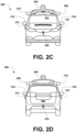
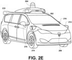
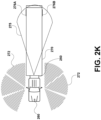
- FIGS 2A-2E show an example vehicle 200 (e.g., a fully autonomous vehicle or semi-autonomous vehicle) that can include some or all of the functions described in connection with vehicle 100 in reference to Figure 1 .
- vehicle 200 is illustrated in Figures 2A-2E as a van with side view mirrors for illustrative purposes, the present disclosure is not so limited.
- the vehicle 200 can represent a truck, a car, a semi-trailer truck, a motorcycle, a golf cart, an off-road vehicle, a farm vehicle, or any other vehicle that is described elsewhere herein (e.g., buses, boats, airplanes, helicopters, drones, lawn mowers, earth movers, submarines, all-terrain vehicles, snowmobiles, aircraft, recreational vehicles, amusement park vehicles, farm equipment, construction equipment or vehicles, warehouse equipment or vehicles, factory equipment or vehicles, trams, trains, trolleys, sidewalk delivery vehicles, and robot devices).
- a truck a car, a semi-trailer truck, a motorcycle, a golf cart, an off-road vehicle, a farm vehicle, or any other vehicle that is described elsewhere herein (e.g., buses, boats, airplanes, helicopters, drones, lawn mowers, earth movers, submarines, all-terrain vehicles, snowmobiles, aircraft, recreational vehicles, amusement park vehicles, farm equipment, construction equipment or vehicles, warehouse equipment or vehicles, factory equipment or vehicles, trams
- a lidar could be utilized in self-driving or other types of navigation, planning, perception, and/or mapping operations of the vehicle 200.
- sensor systems 202, 204, 206, 208, 210, 212, 214, and/or 218 could represent a combination of sensors described herein (e.g., one or more lidars and radars; one or more lidars and cameras; one or more cameras and radars; or one or more lidars, cameras, and radars).
- the sensor system 202 may be mounted atop the vehicle 200 and may include one or more sensors configured to detect information about an environment surrounding the vehicle 200, and output indications of the information.
- sensor system 202 can include any combination of cameras, radars, lidars, inertial sensors, humidity sensors, and acoustic sensors (e.g., microphones and sonar devices).
- the sensor system 202 can include one or more movable mounts that could be operable to adjust the orientation of one or more sensors in the sensor system 202.
- the movable mount could include a rotating platform that could scan sensors so as to obtain information from each direction around the vehicle 200.
- each sensor of sensor system 202 could be distributed in different locations and need not be collocated in a single location.
- each sensor of sensor system 202 can be configured to be moved or scanned independently of other sensors of sensor system 202.
- multiple sensors may be mounted at one or more of the sensor locations 202, 204, 206, 208, 210, 212, 214, and/or 218.
- the one or more sensor systems 202, 204, 206, 208, 210, 212, 214, and/or 218 could include one or more lidar sensors.
- the lidar sensors could include a plurality of light-emitter devices arranged over a range of angles with respect to a given plane (e.g., the x-y plane).
- one or more of the sensor systems 202, 204, 206, 208, 210, 212, 214, and/or 218 may be configured to rotate or pivot about an axis (e.g., the z-axis) perpendicular to the given plane so as to illuminate an environment surrounding the vehicle 200 with light pulses. Based on detecting various aspects of reflected light pulses (e.g., the elapsed time of flight, polarization, and intensity), information about the surrounding environment may be determined.
- sensor systems 202, 204, 206, 208, 210, 212, 214, and/or 218 may be configured to provide respective point cloud information that may relate to physical objects within the surrounding environment of the vehicle 200. While vehicle 200 and sensor systems 202, 204, 206, 208, 210, 212, 214, and 218 are illustrated as including certain features, it will be understood that other types of sensor systems are contemplated within the scope of the present disclosure. Further, the example vehicle 200 can include any of the components described in connection with vehicle 100 of Figure 1 .
- one or more radars can be located near the front of the vehicle 200 (e.g., sensor systems 212 or 214) to actively scan the environment near the front of the vehicle 200.
- a radar can be situated, for example, in a location suitable to illuminate a region including a forward-moving path of the vehicle 200 without occlusion by other features of the vehicle 200.
- a radar can be embedded in and/or mounted in or near the front bumper, front headlights, cowl, and/or hood, etc.
- one or more additional radars can be located to actively scan the side and/or rear of the vehicle 200 for the presence of radio-reflective objects, such as by including such devices in or near the rear bumper, side panels, rocker panels, and/or undercarriage, etc.
- Remote computing system 302 may represent any type of device related to remote assistance techniques, including but not limited to those described herein.
- remote computing system 302 may represent any type of device configured to (i) receive information related to vehicle 200, (ii) provide an interface through which a human operator can in turn perceive the information and input a response related to the information, and (iii) transmit the response to vehicle 200 or to other devices.
- Remote computing system 302 may take various forms, such as a workstation, a desktop computer, a laptop, a tablet, a mobile phone (e.g., a smart phone), and/or a server.
- remote computing system 302 may include multiple computing devices operating together in a network configuration.
- Server computing system 306 may include one or more subsystems and components similar or identical to the subsystems and components of remote computing system 302 and/or vehicle 200, such as a processor configured for performing various operations described herein, and a wireless communication interface for receiving information from, and providing information to, remote computing system 302 and vehicle 200.
- a vehicle may receive data representing objects in an environment surrounding the vehicle (also referred to herein as "environment data") in a variety of ways.
- a sensor system on the vehicle may provide the environment data representing objects of the surrounding environment.
- the vehicle may have various sensors, including a camera, a radar, a lidar, a microphone, a radio unit, and other sensors. Each of these sensors may communicate environment data to a processor in the vehicle about information each respective sensor receives.
- a camera may be configured to capture still images and/or video.
- the vehicle may have more than one camera positioned in different orientations.
- the camera may be able to move to capture images and/or video in different directions.
- the camera may be configured to store captured images and video to a memory for later processing by a processing system of the vehicle.
- the captured images and/or video may be the environment data.
- the camera may include an image sensor as described herein.
- the vehicle can request a human operator (or a more powerful computer) to perform one or more remote assistance tasks, such as (i) confirm whether the object is in fact present in the surrounding environment (e.g., if there is actually a stop sign or if there is actually no stop sign present), (ii) confirm whether the vehicle's identification of the object is correct, (iii) correct the identification if the identification was incorrect, and/or (iv) provide a supplemental instruction (or modify a present instruction) for the autonomous or semi-autonomous vehicle.
- a human operator or a more powerful computer
- the vehicle may detect objects of the surrounding environment in various ways depending on the source of the environment data.
- the environment data may come from a camera and be image or video data.
- the environment data may come from a lidar.
- the vehicle may analyze the captured image or video data to identify objects in the image or video data.
- the methods and apparatuses may be configured to monitor image and/or video data for the presence of objects of the surrounding environment.
- the environment data may be radar, audio, or other data.
- the vehicle may be configured to identify objects of the surrounding environment based on the radar, audio, or other data.
- the techniques the vehicle uses to detect objects may be based on a set of known data. For example, data related to environmental objects may be stored to a memory located in the vehicle. The vehicle may compare received data to the stored data to determine objects. In other embodiments, the vehicle may be configured to determine objects based on the context of the data. For example, street signs related to construction may generally have an orange color. Accordingly, the vehicle may be configured to detect objects that are orange, and located near the side of roadways as construction-related street signs. Additionally, when the processing system of the vehicle detects objects in the captured data, it also may calculate a confidence for each object.
- the actions that the vehicle takes may vary. In some embodiments, the vehicle may react as if the detected object is present despite the low confidence level. In other embodiments, the vehicle may react as if the detected object is not present.
- the vehicle When the vehicle detects an object of the surrounding environment, it may also calculate a confidence associated with the specific detected object.
- the confidence may be calculated in various ways depending on the embodiment. In one example, when detecting objects of the surrounding environment, the vehicle may compare environment data to predetermined data relating to known objects. The closer the match between the environment data and the predetermined data, the higher the confidence. In other embodiments, the vehicle may use mathematical analysis of the environment data to determine the confidence associated with the objects.
- the vehicle may transmit, to the remote computing system, a request for remote assistance with the identification of the object.
- the remote computing system may take various forms.
- the remote computing system may be a computing device within the vehicle that is separate from the vehicle, but with which a human operator can interact while a passenger or driver of the vehicle, such as a touchscreen interface for displaying remote assistance information.
- the remote computing system may be a remote computer terminal or other device that is located at a location that is not near the vehicle.
- the object when the object is detected as having a confidence below the confidence threshold, the object may be given a preliminary identification, and the vehicle may be configured to adjust the operation of the vehicle in response to the preliminary identification.
- Such an adjustment of operation may take the form of stopping the vehicle, switching the vehicle to a human-controlled mode, changing a velocity of the vehicle (e.g., a speed and/or direction), among other possible adjustments.
- the vehicle may operate in accordance with the detected object (e.g., come to a stop if the object is identified with high confidence as a stop sign), but may be configured to request remote assistance at the same time as (or at a later time from) when the vehicle operates in accordance with the detected object.
- Figure 4A is a block diagram of a system, according to example embodiments.
- Figure 4A shows a system 400 that includes a system controller 402, a lidar device 410, a plurality of sensors 412, and a plurality of controllable components 414.
- System controller 402 includes processor(s) 404, a memory 406, and instructions 408 stored on the memory 406 and executable by the processor(s) 404 to perform functions.
- the processor(s) 404 can include one or more processors, such as one or more general-purpose microprocessors (e.g., having a single core or multiple cores) and/or one or more special purpose microprocessors.
- the one or more processors may include, for instance, one or more central processing units (CPUs), one or more microcontrollers, one or more graphical processing units (GPUs), one or more tensor processing units (TPUs), one or more ASICs, and/or one or more field-programmable gate arrays (FPGAs).
- CPUs central processing units
- GPUs graphical processing units
- TPUs tensor processing units
- ASICs application-programmable gate arrays
- FPGAs field-programmable gate arrays
- the lidar device 410 includes a plurality of light emitters configured to emit light (e.g., in light pulses) and one or more light detectors configured to detect light (e.g., reflected portions of the light pulses).
- the lidar device 410 may generate three-dimensional (3D) point cloud data from outputs of the light detector(s), and provide the 3D point cloud data to the system controller 402.
- the system controller 402 may perform operations on the 3D point cloud data to determine the characteristics of a surrounding environment (e.g., relative positions of objects within a surrounding environment, edge detection, object detection, and proximity sensing).
- the system controller 402 may use outputs from the plurality of sensors 412 to determine the characteristics of the system 400 and/or characteristics of the surrounding environment.
- the sensors 412 may include one or more of a GPS, an IMU, an image capture device (e.g., a camera), a light sensor, a heat sensor, and other sensors indicative of parameters relevant to the system 400 and/or the surrounding environment.
- the lidar device 410 is depicted as separate from the sensors 412 for purposes of example, and may be considered as part of or as the sensors 412 in some examples.
- the system controller 402 may control the controllable components 414 to perform one or more actions.
- the system 400 may correspond to a vehicle, in which case the controllable components 414 may include a braking system, a turning system, and/or an accelerating system of the vehicle, and the system controller 402 may change aspects of these controllable components based on characteristics determined from the lidar device 410 and/or sensors 412 (e.g., when the system controller 402 controls the vehicle in an autonomous or semi-autonomous mode).
- the lidar device 410 and the sensors 412 are also controllable by the system controller 402.
- Figure 4B is a block diagram of a lidar device, according to an example embodiment.
- Figure 4B shows a lidar device 410, having a controller 416 configured to control a plurality of light emitters 424 and one or more light detector(s), e.g., a plurality of light detectors 426, etc.
- the lidar device 410 further includes a firing circuit 428 configured to select and provide power to respective light emitters of the plurality of light emitters 424 and may include a selector circuit 430 configured to select respective light detectors of the plurality of light detectors 426.
- the controller 416 includes processor(s) 418, a memory 420, and instructions 422 stored on the memory 420.
- the processor(s) 418 can include one or more processors, such as one or more general-purpose microprocessors and/or one or more special purpose microprocessors.
- the one or more processors may include, for instance, one or more CPUs, one or more microcontrollers, one or more GPUs, one or more TPUs, one or more ASICs, and/or one or more FPGAs.
- Other types of processors, computers, or devices configured to carry out software instructions are also contemplated herein.
- the controller 416 can determine 3D point cloud data by using the light emitters 424 to emit pulses of light.
- a time of emission is established for each light emitter and a relative location at the time of emission is also tracked.
- Aspects of a surrounding environment of the lidar device 410 such as various objects, reflect the pulses of light.
- objects may include vehicles, signs, pedestrians, road surfaces, or construction cones. Some objects may be more reflective than others, such that an intensity of reflected light may indicate a type of object that reflects the light pulses.
- the controller 416 may track a detection time at which a reflected light pulse is detected by a light detector and a relative position of the light detector at the detection time. By measuring time differences between emission times and detection times, the controller 416 can determine how far the light pulses travel prior to being received, and thus a relative distance of a corresponding object. By tracking relative positions at the emission times and detection times the controller 416 can determine an orientation of the light pulse and reflected light pulse relative to the lidar device 410, and thus a relative orientation of the object.
- the controller 416 can determine how reflective the object is.
- the 3D point cloud data determined based on this information may thus indicate relative positions of detected reflected light pulses (e.g., within a coordinate system, such as a Cartesian coordinate system) and intensities of each reflected light pulse.
- the firing circuit 428 is used for selecting light emitters for emitting light pulses.
- the selector circuit 430 similarly is used for sampling outputs from light detectors.
- some sensing devices may include one or more optical components (e.g., lenses, mirrors, waveguides, optical coatings, and/or windows), and one or more defects in or on portions of such optical components can result in improper detections of the surrounding environment.
- optical components e.g., lenses, mirrors, waveguides, optical coatings, and/or windows
- an optical window e.g., an optical element through which a camera or lidar detects the surrounding environment
- an optical window may suffer from one or more scratches, cracks, smudges, deformations, air bubbles, impurities (e.g., chemical impurities within the glass or plastic of the optical window), degradations (e.g., decreased optical properties over time), discolorations, imperfect transparencies, or warpings within (e.g., inside a body of) one or more portions of the optical window.
- such an optical window may suffer from condensation, dirt, dust, mud, leaves, rain snow, sleet, hail, ice, or insect residue (i.e., the remains of dead insects) on one or more portions of the optical window (e.g., on one or more portions of the optical window that interfaces with the surrounding environment, i.e., on one or more exterior portions of the optical window).
- defects is understood to broadly encompass both debris (e.g., from an external environment or from internal to the lidar device) that is present on a surface of one or more components, as well as imperfections within one or more components, themselves (e.g., fabrication imperfections, and degradations)
- the optical component 502 may suffer from defects (e.g., degradations and debris) that degrade performance of the lidar device 410 (e.g., result in internal reflections of light signals from the light emitters 424 that are detected by the light detector(s) 426, as illustrated in Figure 5 ).
- defects may be visible to the naked eye (e.g., a leaf) or invisible to the naked eye (e.g., small debris or minor cracks, deformations, and changes in refractive index).
- single defects may be present on an exterior of the optical component 502, it is understood that any number and/or type of defect(s) are also possible (e.g., on or within the optical component 502).
- the second light detector 426B may detect crosstalk (i.e., detect a crosstalk signal resulting from the emitted signal of the first light emitter 424A) meaning that the second light detector 426B may be undesirably influenced by light from the first channel (e.g., which may result in noise or improper detection events based on the detections of the second light detector 426B).
- crosstalk i.e., detect a crosstalk signal resulting from the emitted signal of the first light emitter 424A
- light signals detected by the light detectors 426A, 426B may have been emitted by the light emitters 424A, 424B and then reflected by something other than target objects in the surrounding environment.
- a defect 622 e.g., debris, such as mud or condensation; a degradation; and a bend / warp present within or on the optical component 502.
- the defect 622 may reflect light signals transmitted by the light emitters 424A, 424B that were intended to probe the surrounding environment and then redirect the light signals to the light detectors 426A, 426B.
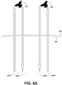
- a first light emitter 424A may emit light signals that are intended for a first light detector 426A when reflected from objects in the surrounding environment (e.g., as illustrated in Figure 6A ) and a second light emitter 424B may emit light signals that are intended for a second light detector 426B when reflected from objects in the surrounding environment (e.g., as illustrated in Figure 6A ).
- emitted light signals when reflected from the defect 622, they may be directed to unintended light detectors.
- a light signal emitted by the first light emitter 424A may be directed to and detected by the second light detector 426B and a light signal emitted by the second light emitter 426B may be directed to and detected by the first light detector 426A (e.g., as illustrated in Figure 6C ).
- such redirected light signals may be partially diffused or otherwise dispersed after interacting with the defect 622. Because such light signals are redirected by the defect 622 to light detectors for which those light signals might not have been originally intended, such redirected light signals may be referred to as "crossfeedback signals" herein.
- an image sensor 632 e.g., a charge-coupled device (CCD)
- CCD charge-coupled device
- the image sensor 632 may be configured to capture an image of the optical window 604 and/or of interior portions of the lidar device.
- the image sensor 632 may be positioned at a focal plane associated with the light detectors 426A, 426B.
- FIG. 6D While not illustrated in Figure 6D , it is understood that additional components may be used to assist the image sensor 632 in capturing an image of the optical component 502 or other portion of the system.
- additional components may be used to assist the image sensor 632 in capturing an image of the optical component 502 or other portion of the system.
- one or more lenses, photographic flashes, mirrors, apertures, etc. may be used in association with the image sensor 632 to capture an image.
- the image may be analyzed (e.g., by a computing device) in order to determine what percentage of the optical component 502 (or other portion of the system), if any, is occluded by one or more defects 622 (e.g., by mud, condensation, cracks, and deformations).
- a machine-learned model e.g., a classifier that was trained on one or more labeled training images, which had known occlusion percentages.
- the percentage of occlusion that is determined may represent an additional metric (e.g., in addition to the intensity, location, timing, etc.
- techniques described herein may include intentionally introducing one or more defects into a system (e.g., into or onto the optical component 502) and then monitoring various metrics (e.g., metrics based on crosstalk signals, crossfeedback signals, and/or captured images) over time to determine the health of the system (e.g., the ability of the system to adequately process, remove, address, account for, etc. defects present within the system).
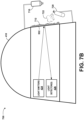
- Figures 7A and 7B illustrate one technique of intentionally introducing defects and monitoring the handling of those defects over time.
- Figures 7A and 7B illustrate a system 700 that includes a lidar device (e.g., the lidar device 410 shown and described with reference to Figures 4A and 4B ), an optical component (e.g., the optical component 502 shown and described with reference to Figures 5-6D ), and a cleaning device.
- the cleaning device may include a sprayer 710 and a pressurized air supply 720.
- the motor spins the lidar device 410
- this may allow the light emitters 424 and light detectors 426 to analyze a larger portion of the surrounding environment (e.g., by azimuthally scanning the surrounding environment).
- the motor when it spins the lidar device 410, it may serve to clean the lidar device 410 (e.g., by removing previously applied cleaning solution or by removing condensation, rain, snow, and debris from the lidar device 410).
- the system 700 of Figure 7A and 7B may be configured to perform a multi-stage cleaning protocol, as illustrated in Figures 7A and 7B .
- Figure 7A illustrates a step of a cleaning protocol.
- the cleaning protocol may include the sprayer 710 applying a cleaning solution 712 to one or more components of the system 700 (e.g., to an exterior surface of the optical component 502).
- the cleaning solution 712 may be applied to a portion of the exterior surface of the optical component 502 or to the entirety of the exterior surface of the optical component 502.
- the cleaning solution 712 may be applied via a nozzle of the sprayer 710, for example.
- the sprayer 710 may also include one or more actuators (e.g., motors and stages) configured to aim the sprayer 710 at specific regions of the lidar device 410 and/or the optical component 502.
- the cleaning solution 712 may include various compounds in various concentrations (e.g., deionized water and isopropyl alcohol). Additionally, the cleaning protocol may include a predefined or selectable number of sprays of cleaning solution 712 to be applied (e.g., one spray, two sprays, three sprays, four sprays, five sprays, six sprays, seven sprays, eight sprays, nine sprays, and ten sprays).
- a predefined or selectable number of sprays of cleaning solution 712 to be applied e.g., one spray, two sprays, three sprays, four sprays, five sprays, six sprays, seven sprays, eight sprays, nine sprays, and ten sprays.
- the number of sprays may be distributed (e.g., evenly) over a predefined or selectable time period (e.g., five seconds, ten seconds, twenty seconds, thirty seconds, and a minute) according to an application frequency (e.g., 0.25 Hz, 0.5 Hz, 0.75 Hz, 1 Hz, 1.5 Hz, 2 Hz, and 2.5 Hz).
- an application frequency e.g. 0.25 Hz, 0.5 Hz, 0.75 Hz, 1 Hz, 1.5 Hz, 2 Hz, and 2.5 Hz.
- the cleaning protocol may be initiated according to a periodic schedule (e.g., once every half hour, once an hour, once every four hours, once every twelve hours, once a day, once every two days, once every four days, once a week, once every two weeks, and once a month).
- the cleaning protocol may be initiated in response to a request (e.g., from a user providing instructions through a mobile application or a browser-based application, from a lidar controller 416, and from a system controller 402). Still further, the cleaning protocol may be initiated in response to one or more thresholds being satisfied (e.g., a determination by the lidar controller 416 that an intensity of or number of detected crossfeedback signals is above a predefined threshold).
- each of the crossfeedback intensities detected during the rain conditions could have its detected intensity adjusted by a fixed amount (e.g., 5%, 10%, 15%, etc. or 1 arb. unit, 2 arb. units, and 3 arb. units).
- the values of A final or ⁇ could also be adjusted after they are determined to account for the rain. For example, the determined ⁇ could be reduced by 5%, 10%, 15%, etc. or by 1 s, 2 s, 3 s, etc.
- internal reflections of light signals emitted by the light emitters 424 may be detected by the light detectors 426 and analyzed (e.g., even if those light signals do not represent crossfeedback signals, i.e., if the light signals were emitted / detected by light emitters 424 / light detectors 426, respectively, in the same channel of the lidar device 410).
- the method 900 may include detecting, by a light detector of the lidar device, reflections of the one or more light signals.
- block 908 may include accounting for a weather condition in a surrounding environment of the lidar device. Further, in some embodiments, accounting for a weather condition in the surrounding environment of the lidar device may include applying one or more offsets to the plot of intensities based on the weather condition.
Landscapes
- Engineering & Computer Science (AREA)
- Physics & Mathematics (AREA)
- Radar, Positioning & Navigation (AREA)
- Remote Sensing (AREA)
- Computer Networks & Wireless Communication (AREA)
- General Physics & Mathematics (AREA)
- Electromagnetism (AREA)
- Optics & Photonics (AREA)
- Mechanical Engineering (AREA)
- Optical Radar Systems And Details Thereof (AREA)
- Traffic Control Systems (AREA)
- Measurement Of Optical Distance (AREA)
Applications Claiming Priority (1)
| Application Number | Priority Date | Filing Date | Title |
|---|---|---|---|
| US18/148,619 US20240219538A1 (en) | 2022-12-30 | 2022-12-30 | Using Cleaning Protocols to Monitor Defects Associated with Light Detection and Ranging (Lidar) Devices |
Publications (1)
| Publication Number | Publication Date |
|---|---|
| EP4394432A1 true EP4394432A1 (fr) | 2024-07-03 |
Family
ID=89308137
Family Applications (1)
| Application Number | Title | Priority Date | Filing Date |
|---|---|---|---|
| EP23219177.5A Pending EP4394432A1 (fr) | 2022-12-30 | 2023-12-21 | Utilisation de protocoles de nettoyage pour surveiller des défauts associés à des dispositifs de détection et de télémétrie par la lumière (lidar) |
Country Status (4)
| Country | Link |
|---|---|
| US (1) | US20240219538A1 (fr) |
| EP (1) | EP4394432A1 (fr) |
| JP (2) | JP7610681B2 (fr) |
| CN (1) | CN118276057A (fr) |
Families Citing this family (2)
| Publication number | Priority date | Publication date | Assignee | Title |
|---|---|---|---|---|
| US20240351558A1 (en) * | 2023-04-18 | 2024-10-24 | Gm Cruise Holdings Llc | Activation of vehicle sensor cleaning systems |
| US20260029517A1 (en) * | 2024-07-24 | 2026-01-29 | GM Global Technology Operations LLC | Sensor contamination identification |
Citations (3)
| Publication number | Priority date | Publication date | Assignee | Title |
|---|---|---|---|---|
| EP3839622A1 (fr) * | 2019-12-16 | 2021-06-23 | PlusAI Corp | Système et procédé pour un système de protection de capteur |
| US20210263153A1 (en) * | 2017-03-29 | 2021-08-26 | Luminar, Llc | Ultrasonic vibrations on a window in a lidar system |
| CN115390049A (zh) * | 2022-08-01 | 2022-11-25 | 奥比中光科技集团股份有限公司 | 发射模组的脏污监测系统、脏污检测方法及相关设备 |
Family Cites Families (11)
| Publication number | Priority date | Publication date | Assignee | Title |
|---|---|---|---|---|
| US11305740B2 (en) | 2017-12-27 | 2022-04-19 | Waymo Llc | Air knife for sensor clearing |
| DK180429B1 (en) * | 2018-11-20 | 2021-04-23 | Motional Ad Llc | Self-cleaning sensor housings |
| US11519840B2 (en) | 2019-01-22 | 2022-12-06 | Ford Global Technologies, Llc | Hydrophobic coating characterization |
| JP2021011242A (ja) | 2019-07-09 | 2021-02-04 | 株式会社小糸製作所 | 車載光学センサユニット |
| US11137485B2 (en) * | 2019-08-06 | 2021-10-05 | Waymo Llc | Window occlusion imager near focal plane |
| US20220390568A1 (en) | 2019-10-23 | 2022-12-08 | Koito Manufacturing Co., Ltd. | Sensor system and sensor unit |
| JP7188361B2 (ja) | 2019-11-15 | 2022-12-13 | トヨタ自動車株式会社 | 車両前部構造 |
| KR102896844B1 (ko) * | 2020-01-07 | 2025-12-04 | 삼성전자주식회사 | 라이다 장치 및 그 동작 방법 |
| EP3885207A1 (fr) * | 2020-03-26 | 2021-09-29 | ZKW Group GmbH | Dispositif de nettoyage pour une visière |
| US20220297638A1 (en) | 2021-03-17 | 2022-09-22 | Pony Al Inc. | Diverting air from a cargo area of a vehicle |
| US20240101072A1 (en) * | 2022-09-26 | 2024-03-28 | Daimler Truck North America Llc | Systems, methods, and technologies for cleaning and maintaining operability of vehicle sensors |
-
2022
- 2022-12-30 US US18/148,619 patent/US20240219538A1/en active Pending
-
2023
- 2023-11-08 JP JP2023190776A patent/JP7610681B2/ja active Active
- 2023-12-21 EP EP23219177.5A patent/EP4394432A1/fr active Pending
- 2023-12-29 CN CN202311846277.1A patent/CN118276057A/zh active Pending
-
2024
- 2024-12-20 JP JP2024225250A patent/JP7818688B2/ja active Active
Patent Citations (3)
| Publication number | Priority date | Publication date | Assignee | Title |
|---|---|---|---|---|
| US20210263153A1 (en) * | 2017-03-29 | 2021-08-26 | Luminar, Llc | Ultrasonic vibrations on a window in a lidar system |
| EP3839622A1 (fr) * | 2019-12-16 | 2021-06-23 | PlusAI Corp | Système et procédé pour un système de protection de capteur |
| CN115390049A (zh) * | 2022-08-01 | 2022-11-25 | 奥比中光科技集团股份有限公司 | 发射模组的脏污监测系统、脏污检测方法及相关设备 |
Also Published As
| Publication number | Publication date |
|---|---|
| JP7818688B2 (ja) | 2026-02-20 |
| CN118276057A (zh) | 2024-07-02 |
| US20240219538A1 (en) | 2024-07-04 |
| JP7610681B2 (ja) | 2025-01-08 |
| JP2024095977A (ja) | 2024-07-11 |
| JP2025081288A (ja) | 2025-05-27 |
Similar Documents
| Publication | Publication Date | Title |
|---|---|---|
| CN113261278B (zh) | 基于杂散光的范围识别光学检测器系统中的缺陷 | |
| US12275430B2 (en) | Identification of proxy calibration targets for a fleet of vehicles | |
| JP6495388B2 (ja) | 車載センサを用いて気象状態を検出する方法及びシステム | |
| JP7818688B2 (ja) | 光検出および測距(ライダー)装置に関連する欠陥を監視するためのクリーニングプロトコルの使用 | |
| JP7522169B2 (ja) | 強い背景光からの飽和を回避し、方向制御を達成するために回転カメラ上のフレーム時間を能動的に調整する、制御ウィンドウカメラの方向付け | |
| EP4344965A2 (fr) | Dispositifs d'essuie-glace pour boîtiers de capteur | |
| US12422563B2 (en) | Differential methods for environment estimation, lidar impairment detection, and filtering | |
| JP2023181970A (ja) | 光検出及び測距(lidar)デバイスにおける近くの物体検出のための光検出器 | |
| EP4184199A1 (fr) | Systèmes, procédés et appareil pour déterminer des caractéristiques d'un radôme | |
| JP2025165921A (ja) | 光検出および測距(LiDAR)装置ならびにカメラにおける欠陥検出のための時間的に変調された光の放射 | |
| US20230358868A1 (en) | Mitigating Crosstalk from High-Intensity Returns in a Light Detection and Ranging (Lidar) Device | |
| JP7702452B2 (ja) | 光検出及び測距(lider)デバイスにおけるクロストーク軽減のための時間分割多重アクセススキャニング | |
| US12561942B2 (en) | Multi-channel dynamic weather estimation | |
| HK40108187A (en) | Wiper devices for sensor housings |
Legal Events
| Date | Code | Title | Description |
|---|---|---|---|
| PUAI | Public reference made under article 153(3) epc to a published international application that has entered the european phase |
Free format text: ORIGINAL CODE: 0009012 |
|
| STAA | Information on the status of an ep patent application or granted ep patent |
Free format text: STATUS: THE APPLICATION HAS BEEN PUBLISHED |
|
| AK | Designated contracting states |
Kind code of ref document: A1 Designated state(s): AL AT BE BG CH CY CZ DE DK EE ES FI FR GB GR HR HU IE IS IT LI LT LU LV MC ME MK MT NL NO PL PT RO RS SE SI SK SM TR |
|
| STAA | Information on the status of an ep patent application or granted ep patent |
Free format text: STATUS: REQUEST FOR EXAMINATION WAS MADE |
|
| 17P | Request for examination filed |
Effective date: 20241211 |