EP4394535A1 - Automatisierungssystem mit einem ausrüstungsprüfwagen - Google Patents
Automatisierungssystem mit einem ausrüstungsprüfwagen Download PDFInfo
- Publication number
- EP4394535A1 EP4394535A1 EP23150009.1A EP23150009A EP4394535A1 EP 4394535 A1 EP4394535 A1 EP 4394535A1 EP 23150009 A EP23150009 A EP 23150009A EP 4394535 A1 EP4394535 A1 EP 4394535A1
- Authority
- EP
- European Patent Office
- Prior art keywords
- equipment
- carriage
- automation equipment
- inspecting
- automation
- Prior art date
- Legal status (The legal status is an assumption and is not a legal conclusion. Google has not performed a legal analysis and makes no representation as to the accuracy of the status listed.)
- Pending
Links
Images



Classifications
-
- G—PHYSICS
- G05—CONTROLLING; REGULATING
- G05B—CONTROL OR REGULATING SYSTEMS IN GENERAL; FUNCTIONAL ELEMENTS OF SUCH SYSTEMS; MONITORING OR TESTING ARRANGEMENTS FOR SUCH SYSTEMS OR ELEMENTS
- G05B23/00—Testing or monitoring of control systems or parts thereof
- G05B23/02—Electric testing or monitoring
- G05B23/0205—Electric testing or monitoring by means of a monitoring system capable of detecting and responding to faults
- G05B23/0259—Electric testing or monitoring by means of a monitoring system capable of detecting and responding to faults characterized by the response to fault detection
- G05B23/0267—Fault communication, e.g. human machine interface [HMI]
- G05B23/027—Alarm generation, e.g. communication protocol; Forms of alarm
-
- G—PHYSICS
- G05—CONTROLLING; REGULATING
- G05B—CONTROL OR REGULATING SYSTEMS IN GENERAL; FUNCTIONAL ELEMENTS OF SUCH SYSTEMS; MONITORING OR TESTING ARRANGEMENTS FOR SUCH SYSTEMS OR ELEMENTS
- G05B23/00—Testing or monitoring of control systems or parts thereof
- G05B23/02—Electric testing or monitoring
- G05B23/0205—Electric testing or monitoring by means of a monitoring system capable of detecting and responding to faults
- G05B23/0208—Electric testing or monitoring by means of a monitoring system capable of detecting and responding to faults characterized by the configuration of the monitoring system
-
- G—PHYSICS
- G05—CONTROLLING; REGULATING
- G05D—SYSTEMS FOR CONTROLLING OR REGULATING NON-ELECTRIC VARIABLES
- G05D1/00—Control of position, course, altitude or attitude of land, water, air or space vehicles, e.g. using automatic pilots
- G05D1/20—Control system inputs
- G05D1/24—Arrangements for determining position or orientation
- G05D1/243—Means capturing signals occurring naturally from the environment, e.g. ambient optical, acoustic, gravitational or magnetic signals
-
- G—PHYSICS
- G05—CONTROLLING; REGULATING
- G05D—SYSTEMS FOR CONTROLLING OR REGULATING NON-ELECTRIC VARIABLES
- G05D1/00—Control of position, course, altitude or attitude of land, water, air or space vehicles, e.g. using automatic pilots
- G05D1/60—Intended control result
- G05D1/656—Interaction with payloads or external entities
- G05D1/689—Pointing payloads towards fixed or moving targets
-
- G—PHYSICS
- G05—CONTROLLING; REGULATING
- G05B—CONTROL OR REGULATING SYSTEMS IN GENERAL; FUNCTIONAL ELEMENTS OF SUCH SYSTEMS; MONITORING OR TESTING ARRANGEMENTS FOR SUCH SYSTEMS OR ELEMENTS
- G05B2219/00—Program-control systems
- G05B2219/20—Pc systems
- G05B2219/24—Pc safety
- G05B2219/24097—Camera monitors controlled machine
-
- G—PHYSICS
- G05—CONTROLLING; REGULATING
- G05B—CONTROL OR REGULATING SYSTEMS IN GENERAL; FUNCTIONAL ELEMENTS OF SUCH SYSTEMS; MONITORING OR TESTING ARRANGEMENTS FOR SUCH SYSTEMS OR ELEMENTS
- G05B2219/00—Program-control systems
- G05B2219/30—Nc systems
- G05B2219/36—Nc in input of data, input key till input tape
- G05B2219/36487—Record position, motion and sound
-
- G—PHYSICS
- G05—CONTROLLING; REGULATING
- G05B—CONTROL OR REGULATING SYSTEMS IN GENERAL; FUNCTIONAL ELEMENTS OF SUCH SYSTEMS; MONITORING OR TESTING ARRANGEMENTS FOR SUCH SYSTEMS OR ELEMENTS
- G05B2219/00—Program-control systems
- G05B2219/30—Nc systems
- G05B2219/37—Measurements
- G05B2219/37337—Noise, acoustic emission, sound
Definitions
- the present disclosure relates to an equipment inspecting arrangement, an automation system as well as to a method of controlling an equipment inspecting carriage in the automation system.
- the object is according to a second aspect achieved through a method of controlling an equipment inspecting carriage in an automation system comprising automation equipment including a first piece of automation equipment in a first area of the automation system, the first area being an automation equipment environment for the first piece of automation equipment and the equipment inspecting carriage comprising an image capturing device and a sound registering arrangement, the method comprising:
- the method further comprises determining a distance from the image capturing device to the point of interest based on the received sounds and the adjusting is based also on the determined distance.
- the sound registering arrangement is moveable between two different arrangement positions and the distance is determined based on the sounds registered at the two arrangement positions.
- the carriage control unit is further operative to control the image capturing device to capture images of the first piece of automation equipment and receive the images from the image capturing device, where the diagnosing data of the first piece of automation equipment also comprises the received images.
- the equipment inspecting carriage may further comprise a sensor device operative to sense physical properties of the automation equipment environment.
- the carriage control unit is in this case further operative to receive the sensed physical properties of the automation equipment environment, where the diagnosing data of the first piece of automation equipment also comprises the sensed physical properties of the automation equipment environment.
- the method further comprises receiving the sensed physical properties of the automation equipment environment, where the diagnosing data of the first piece of automation equipment also comprises the sensed physical properties of the automation equipment environment.
- a third aspect of the invention is concerned with an automation system comprising automation equipment including the first piece of automation equipment in the first area of the automation system, an alert handling device and the equipment inspecting arrangement according to the first aspect.
- the alert handling device is operative to control the equipment inspecting carriage to move on the track to the first track position in the automation equipment environment.
- the method further comprises controlling the equipment inspecting carriage to move on the track to the first track position in the automation equipment environment.
- the alert handling device is operative to obtain an alert regarding the first piece of automation equipment and the control of the equipment inspecting carriage to move to the first track position is based on the alert.
- the method further comprises obtaining an alert regarding the first piece of automation equipment and where the controlling of the equipment inspecting carriage to move to the first track position is based on the alert.
- the adjusting may involve moving the equipment inspecting carriage to a track position for which the distance between the image capturing device and the point of interest is the shortest and/or for which there is a line of sight between the point of interest and the image capturing device.
- the adjusting may additionally or instead comprise changing the orientation of the image capturing device such that it points towards the point of interest.
- Fig. 1 is a diagram schematically illustrating an automation system AS 10.
- the automation system 10 maybe a process control system for controlling an industrial process or perhaps part of an industrial process.
- Typical processes are electrical power generation, transmission, distribution and supply processes, water purification and distribution processes, oil and gas production and distribution processes, petrochemical, chemical, pharmaceutical and food processes, and pulp and paper production processes. These are just some examples of processes where the system can be applied.
- the process may be monitored through an operator terminal or workstation. Such a workstation or operator terminal is also a form of user terminal.
- the automation system 10 therefore includes a number of user terminals, here exemplified by a first user terminal UT1 12 and a second user terminal UT2 14, connected to a first bus B1.
- a first bus B1 There is furthermore a second bus B2 and between the first and second busses B1 and B2 there are connected a process control device PCD 16 with a control function for controlling the process, a safety control device SCD 18 which performs safety control in the process and a condition monitoring device CMD 19.
- a process control device PCD 16 with a control function for controlling the process
- SCD 18 which performs safety control in the process
- CMD 19 condition monitoring device
- the automation equipment may comprise one or more controllers having some local software for controlling other automation equipment such as field devices.
- the automation equipment may also comprise such field devices.
- the field devices may comprise devices that influence or measure different properties of a technical process.
- a field device may for instance be a pump, a motor, a valve, etc.
- a process, or a part of a process may be controlled via the process control device 16, which then typically communicates with a controller for providing local control using field devices.
- the safety control device 18 may in similar manner control safety in the automation system 10, while the condition monitoring device 19 monitors the condition or health of the automation devices.
- the automation equipment 20, 22, 24, 26, 28, 30 is located in a first automation equipment environment AEE 31, which may be located remotely from a control room environment where the user terminals 12, 14 are located.
- the automation equipment environment 31 may additionally or instead be a harsh or hostile environment, such as an environment that is gaseous or aqueous or an environment that is otherwise unsuitable for humans. It may for instance have a high and/or low pressure or a high or low temperature.
- the safety control device 18 also comprises a first Input/Output interface I/O 1 38 for communicating with other devices such as the automation equipment 20, 22, 24, 26, 28, 30. It also comprises a second Input/Output interface I/O 2 40 which is used for communicating with an equipment inspecting carriage.
- the first I/O interface 38 may be an Ethernet interface or a fieldbus interface and the second I/O interface 40 may be a wireless interface.
- process control device 16 and the condition monitoring device 19 have the same or similar type of realization as the safety control device 18.
- the equipment inspecting carriage 44 also comprises a carriage control unit CCU 52.
- the sound registering arrangement 48 may comprise one or more sound registering devices and may more particularly comprise an array of sound registering devices, which may be microphones. These microphones may additionally be directional microphones.
- the image capturing device 46 may be a camera and may with advantage be a video camera. The image capturing device 46 may additionally have an orientation that is adjustable so that it can be pointed in different directions. It may also have zoom capability.
- Fig. 5 schematically shows the safety control device SCD 18 communicating with the carriage control unit CCU 52.
- the safety control device 18 may send a control command CC to the carriage control unit 52 and the carriage control unit 52 may send diagnosing data DD to the safety control device 18.
- the sound registering arrangement 48 may thus be moveable between two different arrangement positions, here corresponding to the first and the second track positions P1 and P2 and the distance is determined based on the sounds registered at these two arrangement positions.
- the sound registering arrangement 48 may be moveable on the equipment inspecting carriage 44, so that the sounds are registered at two different positions of the sound registering arrangement 48 on the equipment inspecting carriage 44, while the equipment inspecting carriage is at the first track position P1.
- the equipment inspecting carriage 44 can be moved to the second position P2 even if the distance and direction have been determined. This may be done in order to confirm the determined direction and distance.
- the carriage control function of the carriage control unit 52 then adjusts the track position of the equipment inspecting carriage 44 and/or the orientation of the image capturing device 46 based on the determined direction and optionally also based on the determined distance, S170.
- the adjusting may involve moving the equipment inspecting carriage 44 to a track position for which the distance between the image capturing device 46 and the point of interest POI is the shortest. It may instead be a track position for which there is a line of sight between the point of interest POI and the image capturing device 46. Furthermore, it may be the shortest distance for which there is a line of sight between the point of interest POI and the image capturing device.
- the adjusting may additionally or instead comprise changing the orientation of the image capturing device 46 such that it points towards the point of interest POI.
- the carriage control function of the carriage control unit 52 continues to receive diagnosing data DD, S180. It thus continues to receive sounds from the sound registering arrangement 48, images from the image capturing device 46 and possibly also physical properties of the automation equipment environment 31 from the sensor device 50.
- the diagnosing data DD can be used for assisting the safety control device 18, which is done when the safety control device acts as an alert handling device.
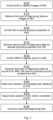
- Fig, 8 shows a flow chart of a number of further steps in the method of controlling the equipment inspecting carriage, which method steps are being performed by the alert handling function of the safety control device 18.
- the alert handling function of the safety control device 18 acting as an alert handling device may obtain an alert regarding the first piece of automation equipment 20, S200.
- the alert which may be an alarm, may be received from a sensor in or at the first automation equipment 20.
- the alert handling device may determine the alert based on received sensor measurements of the first piece of automation equipment.
- the alert may be displayed to an alarm operator at a user terminal in the control room environment, such as at the first user terminal 12. Based on this alert the operator or the alert handling function of the safety control device 18 may control the equipment inspecting carriage 44 to move to the first track position P1 in the automation equipment environment 31, S210.
- control command CC may be an instruction to move the equipment inspecting carriage 44 to the first track position P1, and to gather diagnosing data DD.
- the first track position P1 may in this case be a nominal data gathering position associated with the first piece of automation equipment 20.
- the carriage control function of the carriage control unit 52 may receive this control command CC and may then control the equipment inspecting carriage 44 to move on the track 42 to the first track position P1 in the automation equipment environment 31, for instance through controlling a motor of the equipment inspecting carriage 44.
- the equipment inspecting carriage 44 may therefore move from outside of the automation equipment environment 31 to within it.
- the carriage control function of the carriage control unit 52 may then receive the different types of diagnosing data DD in the previously described way.
- the alert handling function of the safety control device 18 collects the diagnosing data DD from the equipment inspecting carriage, S220, which may be done as soon as the carriage control unit 52 receives the diagnosing data.
- the collecting may be performed through the carriage control function of the carriage control unit 52 sending the diagnosing data DD to the alert handling function of the safety control device 18, for instance wirelessly.
- the diagnosing data DD may then be displayed to the alarm operator at the first user terminal 12, who may then perform an activity such as a safety activity.
- the alert handling function of the safety control device 18 may determine the activity itself based on the collected diagnosing data, S230. After the activity has been determined, the alert handling function of the safety control device 18 may then perform the activity, S240.
- the activity may involve a number of actions, such as stopping or halting operation of one or more of the pieces of automation equipment in the first automation equipment environment including the first piece of automation equipment.
Landscapes
- Engineering & Computer Science (AREA)
- Physics & Mathematics (AREA)
- General Physics & Mathematics (AREA)
- Automation & Control Theory (AREA)
- Aviation & Aerospace Engineering (AREA)
- Radar, Positioning & Navigation (AREA)
- Remote Sensing (AREA)
- Human Computer Interaction (AREA)
- Testing Of Devices, Machine Parts, Or Other Structures Thereof (AREA)
- Control Of Position, Course, Altitude, Or Attitude Of Moving Bodies (AREA)
- Testing And Monitoring For Control Systems (AREA)
Priority Applications (5)
| Application Number | Priority Date | Filing Date | Title |
|---|---|---|---|
| EP23150009.1A EP4394535A1 (de) | 2023-01-02 | 2023-01-02 | Automatisierungssystem mit einem ausrüstungsprüfwagen |
| CN202380090009.3A CN120457403B (zh) | 2023-01-02 | 2023-12-28 | 包括装备检查滑架的自动化系统 |
| PCT/EP2023/087927 WO2024146860A1 (en) | 2023-01-02 | 2023-12-28 | An automation system comprising an equipment inspecting carriage |
| JP2025538877A JP7848416B2 (ja) | 2023-01-02 | 2023-12-28 | 機器検査台車を備える自動化システム |
| US19/256,742 US20250328129A1 (en) | 2023-01-02 | 2025-07-01 | Automation System Comprising an Equipment Inspecting Carriage |
Applications Claiming Priority (1)
| Application Number | Priority Date | Filing Date | Title |
|---|---|---|---|
| EP23150009.1A EP4394535A1 (de) | 2023-01-02 | 2023-01-02 | Automatisierungssystem mit einem ausrüstungsprüfwagen |
Publications (1)
| Publication Number | Publication Date |
|---|---|
| EP4394535A1 true EP4394535A1 (de) | 2024-07-03 |
Family
ID=84820290
Family Applications (1)
| Application Number | Title | Priority Date | Filing Date |
|---|---|---|---|
| EP23150009.1A Pending EP4394535A1 (de) | 2023-01-02 | 2023-01-02 | Automatisierungssystem mit einem ausrüstungsprüfwagen |
Country Status (5)
| Country | Link |
|---|---|
| US (1) | US20250328129A1 (de) |
| EP (1) | EP4394535A1 (de) |
| JP (1) | JP7848416B2 (de) |
| CN (1) | CN120457403B (de) |
| WO (1) | WO2024146860A1 (de) |
Citations (3)
| Publication number | Priority date | Publication date | Assignee | Title |
|---|---|---|---|---|
| EP0961189A1 (de) * | 1998-05-27 | 1999-12-01 | Beb Erdgas Und Erdöl Gmbh | Verfahren und Vorrichtung zur Überwachung von Anlagen der chemischen Industrie |
| CN203616653U (zh) * | 2013-12-19 | 2014-05-28 | 成都慧拓自动控制技术有限公司 | 一种轨道智能巡检机器人 |
| CN114986485A (zh) * | 2022-05-10 | 2022-09-02 | 浙江华云信息科技有限公司 | 一种模块化的轨道巡检机器人 |
Family Cites Families (9)
| Publication number | Priority date | Publication date | Assignee | Title |
|---|---|---|---|---|
| AT364248B (de) * | 1978-03-23 | 1981-10-12 | Eumig | Filmkamera |
| US5550758A (en) * | 1994-03-29 | 1996-08-27 | General Electric Company | Augmented reality maintenance system with flight planner |
| US20060244830A1 (en) * | 2002-06-04 | 2006-11-02 | Davenport David M | System and method of navigation with captured images |
| KR100763901B1 (ko) * | 2005-01-26 | 2007-10-05 | 삼성전자주식회사 | 이동체 제어 장치 및 방법 |
| CA2656268A1 (en) * | 2006-08-03 | 2008-02-07 | International Business Machines Corporation | Video surveillance system and method with combined video and audio recognition |
| CN104469154B (zh) * | 2014-12-05 | 2017-09-26 | 合肥国科声拓信息技术有限公司 | 一种基于麦克风阵列的摄像头引导装置及引导方法 |
| KR20170010485A (ko) * | 2015-07-20 | 2017-02-01 | 엘지전자 주식회사 | 단말 장치 및 단말 장치의 제어 방법 |
| CN114800570A (zh) * | 2022-05-17 | 2022-07-29 | 苏州中图文化科技有限公司 | 一种展厅数字巡检的方法 |
| CN115056236A (zh) * | 2022-05-30 | 2022-09-16 | 华润电力(宁武)有限公司 | 一种电厂智能巡检机器人 |
-
2023
- 2023-01-02 EP EP23150009.1A patent/EP4394535A1/de active Pending
- 2023-12-28 JP JP2025538877A patent/JP7848416B2/ja active Active
- 2023-12-28 CN CN202380090009.3A patent/CN120457403B/zh active Active
- 2023-12-28 WO PCT/EP2023/087927 patent/WO2024146860A1/en not_active Ceased
-
2025
- 2025-07-01 US US19/256,742 patent/US20250328129A1/en active Pending
Patent Citations (3)
| Publication number | Priority date | Publication date | Assignee | Title |
|---|---|---|---|---|
| EP0961189A1 (de) * | 1998-05-27 | 1999-12-01 | Beb Erdgas Und Erdöl Gmbh | Verfahren und Vorrichtung zur Überwachung von Anlagen der chemischen Industrie |
| CN203616653U (zh) * | 2013-12-19 | 2014-05-28 | 成都慧拓自动控制技术有限公司 | 一种轨道智能巡检机器人 |
| CN114986485A (zh) * | 2022-05-10 | 2022-09-02 | 浙江华云信息科技有限公司 | 一种模块化的轨道巡检机器人 |
Also Published As
| Publication number | Publication date |
|---|---|
| CN120457403A (zh) | 2025-08-08 |
| JP2026504281A (ja) | 2026-02-04 |
| CN120457403B (zh) | 2026-05-08 |
| WO2024146860A1 (en) | 2024-07-11 |
| JP7848416B2 (ja) | 2026-04-20 |
| US20250328129A1 (en) | 2025-10-23 |
Similar Documents
| Publication | Publication Date | Title |
|---|---|---|
| CN109001649B (zh) | 一种电源智能诊断系统及保护方法 | |
| EP2193413B1 (de) | System zum erhalten und anzeigen von mit einer abnormen situation assoziierten prozesssteuerdaten | |
| EP1111550B1 (de) | Verfahren und Vorrichtung zur Überwachung des Betriebszustandes einer einzelnen Maschine | |
| EP3235611B1 (de) | Vorrichtung und verfahren zur roboterwartungsunterstützung | |
| CN104678946B (zh) | I/o 模块以及过程控制系统 | |
| JP2000210800A (ja) | 産業機械のモニタ方法およびその装置 | |
| JP2019164751A (ja) | 無人移動ユニットおよび巡回点検システム | |
| JP2017531862A (ja) | 無線工業プロセスモニタ | |
| CN118678315A (zh) | 一种钻机远程云平台的监控系统及方法 | |
| WO2019176710A1 (ja) | 無人移動ユニットおよび巡回点検システム | |
| US20250328129A1 (en) | Automation System Comprising an Equipment Inspecting Carriage | |
| JPH09265316A (ja) | プラント設備点検装置およびプラント設備点検システム | |
| KR20250157324A (ko) | 다중 음향 식별 장치 및 이를 이용한 설비이상 경보 시스템 | |
| US20230265871A1 (en) | Detection of an anomaly in a fluid power system | |
| JPH02136793A (ja) | プラント異常点検装置 | |
| WO2015007583A1 (de) | Detektion eines reinigungsvorganges einer anlage mit örtlich von einander versetzt angeordneten filtern | |
| JPH07128098A (ja) | 計装設備遠隔診断システム | |
| JP7607413B2 (ja) | プラント監視制御システム | |
| CN114967463B (zh) | 一种状态监测模型自学习方法及系统 | |
| KR102238614B1 (ko) | 기계 또는 기기의 오작동 발생 상황 저장 장치 및 그에 의한 저장 방법 | |
| JP3124414B2 (ja) | 監視制御装置 | |
| EP4336291A1 (de) | Systeme und verfahren zur diagnose von herstellungssystemen | |
| JPH06121315A (ja) | 監視制御装置 | |
| JP7596207B2 (ja) | 情報処理装置、データ抽出方法、機械学習モデルの生成方法、およびデータ抽出プログラム | |
| KR20230158943A (ko) | 반도체 공정 유틸리티를 포함하는 설비의 열화와 이상을 사전 감지하는 시스템 및 그를 이용한 사전 감지 방법 |
Legal Events
| Date | Code | Title | Description |
|---|---|---|---|
| PUAI | Public reference made under article 153(3) epc to a published international application that has entered the european phase |
Free format text: ORIGINAL CODE: 0009012 |
|
| STAA | Information on the status of an ep patent application or granted ep patent |
Free format text: STATUS: THE APPLICATION HAS BEEN PUBLISHED |
|
| AK | Designated contracting states |
Kind code of ref document: A1 Designated state(s): AL AT BE BG CH CY CZ DE DK EE ES FI FR GB GR HR HU IE IS IT LI LT LU LV MC ME MK MT NL NO PL PT RO RS SE SI SK SM TR |
|
| STAA | Information on the status of an ep patent application or granted ep patent |
Free format text: STATUS: REQUEST FOR EXAMINATION WAS MADE |
|
| 17P | Request for examination filed |
Effective date: 20241212 |
|
| STAA | Information on the status of an ep patent application or granted ep patent |
Free format text: STATUS: EXAMINATION IS IN PROGRESS |
|
| 17Q | First examination report despatched |
Effective date: 20250407 |