EP4394548A1 - Flexible anzeige und elektronische vorrichtung damit - Google Patents
Flexible anzeige und elektronische vorrichtung damit Download PDFInfo
- Publication number
- EP4394548A1 EP4394548A1 EP22916552.7A EP22916552A EP4394548A1 EP 4394548 A1 EP4394548 A1 EP 4394548A1 EP 22916552 A EP22916552 A EP 22916552A EP 4394548 A1 EP4394548 A1 EP 4394548A1
- Authority
- EP
- European Patent Office
- Prior art keywords
- area
- electronic device
- housing
- display
- rib
- Prior art date
- Legal status (The legal status is an assumption and is not a legal conclusion. Google has not performed a legal analysis and makes no representation as to the accuracy of the status listed.)
- Pending
Links
Images













Classifications
-
- G—PHYSICS
- G06—COMPUTING OR CALCULATING; COUNTING
- G06F—ELECTRIC DIGITAL DATA PROCESSING
- G06F1/00—Details not covered by groups G06F3/00 - G06F13/00 and G06F21/00
- G06F1/16—Constructional details or arrangements
-
- G—PHYSICS
- G06—COMPUTING OR CALCULATING; COUNTING
- G06F—ELECTRIC DIGITAL DATA PROCESSING
- G06F1/00—Details not covered by groups G06F3/00 - G06F13/00 and G06F21/00
- G06F1/16—Constructional details or arrangements
- G06F1/1613—Constructional details or arrangements for portable computers
- G06F1/1615—Constructional details or arrangements for portable computers with several enclosures having relative motions, each enclosure supporting at least one I/O or computing function
- G06F1/1624—Constructional details or arrangements for portable computers with several enclosures having relative motions, each enclosure supporting at least one I/O or computing function with sliding enclosures, e.g. sliding keyboard or display
-
- G—PHYSICS
- G06—COMPUTING OR CALCULATING; COUNTING
- G06F—ELECTRIC DIGITAL DATA PROCESSING
- G06F1/00—Details not covered by groups G06F3/00 - G06F13/00 and G06F21/00
- G06F1/16—Constructional details or arrangements
- G06F1/1613—Constructional details or arrangements for portable computers
- G06F1/1633—Constructional details or arrangements of portable computers not specific to the type of enclosures covered by groups G06F1/1615 - G06F1/1626
- G06F1/1635—Details related to the integration of battery packs and other power supplies such as fuel cells or integrated AC adapter
-
- G—PHYSICS
- G06—COMPUTING OR CALCULATING; COUNTING
- G06F—ELECTRIC DIGITAL DATA PROCESSING
- G06F1/00—Details not covered by groups G06F3/00 - G06F13/00 and G06F21/00
- G06F1/16—Constructional details or arrangements
- G06F1/1613—Constructional details or arrangements for portable computers
- G06F1/1633—Constructional details or arrangements of portable computers not specific to the type of enclosures covered by groups G06F1/1615 - G06F1/1626
- G06F1/1637—Details related to the display arrangement, including those related to the mounting of the display in the housing
- G06F1/1652—Details related to the display arrangement, including those related to the mounting of the display in the housing the display being flexible, e.g. mimicking a sheet of paper, or rollable
-
- G—PHYSICS
- G06—COMPUTING OR CALCULATING; COUNTING
- G06F—ELECTRIC DIGITAL DATA PROCESSING
- G06F1/00—Details not covered by groups G06F3/00 - G06F13/00 and G06F21/00
- G06F1/16—Constructional details or arrangements
- G06F1/1613—Constructional details or arrangements for portable computers
- G06F1/1633—Constructional details or arrangements of portable computers not specific to the type of enclosures covered by groups G06F1/1615 - G06F1/1626
- G06F1/1675—Miscellaneous details related to the relative movement between the different enclosures or enclosure parts
-
- G—PHYSICS
- G09—EDUCATION; CRYPTOGRAPHY; DISPLAY; ADVERTISING; SEALS
- G09F—DISPLAYING; ADVERTISING; SIGNS; LABELS OR NAME-PLATES; SEALS
- G09F9/00—Indicating arrangements for variable information in which the information is built-up on a support by selection or combination of individual elements
- G09F9/30—Indicating arrangements for variable information in which the information is built-up on a support by selection or combination of individual elements in which the desired character or characters are formed by combining individual elements
Definitions
- the disclosure relates to a flexible display and an electronic device including the same.
- smartphones pack the functionalities of a sound player, imaging device, and scheduler, as well as the communication functionality and, on top of that, may implement more various functions by having applications installed thereon.
- the mounting space of the electronic device may be limited by newly required driving structures, such as the space where the display is rolled, the structure supporting the display, the driver for slide-in and slide-out motion, and/or the gap between mechanisms for driving.
- an electronic device includes a first housing, a second housing, the first housing being slidable with respect to the second housing, a flexible display including a first display area and a second display area extending from the first display area, the second display area being flexible in at least one direction, a battery disposed in the first housing or the second housing, and a supporting structure supporting at least a portion of the flexible display.
- the supporting structure includes a first area overlapping the battery and a second area extending from the first area.
- the first area of the supporting structure has a first thickness
- the second area of the supporting structure has a second thickness larger than the first thickness.
- an electronic device includes a first housing, a second housing receiving at least a portion of the first housing, the first housing being slidable with respect to the second housing, a flexible display including a first display area and a second display area extending from the first display area, the second display area being bendable or rollable, a supporting structure supporting at least a portion of the flexible display, and a rib structure including a fixing portion coupled with a portion of the supporting structure and a stepped portion extending from the fixing portion and coupled to the first housing.
- the electronic device it is possible to enhance the performance of the internal components by forming a recess shape in the supporting structure for the flexible display and increasing the volume of the internal components (e.g., battery and camera module) up to a partial area of the recess shape.
- the internal components e.g., battery and camera module
- FIG. 1 is a block diagram illustrating an electronic device in a network environment according to an embodiment of the disclosure.
- the electronic device 101 in the network environment 100 may communicate with an external electronic device 102 via a first network 198 (e.g., a short-range wireless communication network), or an external electronic device 104 or a server 108 via a second network 199 (e.g., a long-range wireless communication network).
- a first network 198 e.g., a short-range wireless communication network
- an external electronic device 104 or a server 108 via a second network 199 (e.g., a long-range wireless communication network).
- the electronic device 101 may communicate with the external electronic device 104 via the server 108.
- the electronic device 101 may include a processor 120, memory 130, an input module 150, a sound output module 155, a display module 160, an audio module 170, a sensor module 176, an interface 177, a connecting terminal 178, a haptic module 179, a camera module 180, a power management module 188, a battery 189, a communication module 190, a subscriber identification module (SIM) 196, or an antenna module 197.
- at least one (e.g., the connecting terminal 178) of the components may be omitted from the electronic device 101, or one or more other components may be added in the electronic device 101.
- some (e.g., the sensor module 176, the camera module 180, or the antenna module 197) of the components may be integrated into a single component (e.g., the display module 160).
- the processor 120 may execute, for example, software (e.g., a program 140) to control at least one other component (e.g., a hardware or software component) of the electronic device 101 coupled with the processor 120, and may perform various data processing or computation.
- the processor 120 may store a command or data received from another component (e.g., the sensor module 176 or the communication module 190) in volatile memory 132, process the command or the data stored in the volatile memory 132, and store resulting data in non-volatile memory 134.
- the non-volatile memory 134 may include one or more of an internal memory 136 or an external memory 138.
- the processor 120 may include a main processor 121 (e.g., a central processing unit (CPU) or an application processor (AP)), or an auxiliary processor 123 (e.g., a graphics processing unit (GPU), a neural processing unit (NPU), an image signal processor (ISP), a sensor hub processor, or a communication processor (CP)) that is operable independently from, or in conjunction with, the main processor 121.
- a main processor 121 e.g., a central processing unit (CPU) or an application processor (AP)
- auxiliary processor 123 e.g., a graphics processing unit (GPU), a neural processing unit (NPU), an image signal processor (ISP), a sensor hub processor, or a communication processor (CP)
- the main processor 121 may be configured to use lower power than the main processor 121 or to be specified for a designated function.
- the auxiliary processor 123 may be implemented as separate from, or as part of the main processor 121.
- the auxiliary processor 123 may control at least some of functions or states related to at least one component (e.g., the display module 160, the sensor module 176, or the communication module 190) among the components of the electronic device 101, instead of the main processor 121 while the main processor 121 is in an inactive (e.g., sleep) state, or together with the main processor 121 while the main processor 121 is in an active state (e.g., executing an application).
- the auxiliary processor 123 e.g., an image signal processor or a communication processor
- the auxiliary processor 123 may include a hardware structure specified for artificial intelligence model processing.
- the artificial intelligence model may be generated via machine learning. Such learning may be performed, e.g., by the electronic device 101 where the artificial intelligence is performed or via a separate server (e.g., the server 108). Learning algorithms may include, but are not limited to, e.g., supervised learning, unsupervised learning, semi-supervised learning, or reinforcement learning.
- the artificial intelligence model may include a plurality of artificial neural network layers.
- the artificial neural network may be a deep neural network (DNN), a convolutional neural network (CNN), a recurrent neural network (RNN), a restricted Boltzmann machine (RBM), a deep belief network (DBN), a bidirectional recurrent deep neural network (BRDNN), deep Q-network or a combination of two or more thereof but is not limited thereto.
- the artificial intelligence model may, additionally or alternatively, include a software structure other than the hardware structure.
- the memory 130 may store various data used by at least one component (e.g., the processor 120 or the sensor module 176) of the electronic device 101.
- the various data may include, for example, software (e.g., the program 140) and input data or output data for a command related thereto.
- the memory 130 may include the volatile memory 132 or the non-volatile memory 134.
- the program 140 may be stored in the memory 130 as software, and may include, for example, an operating system (OS) 142, middleware 144, or an application 146.
- OS operating system
- middleware middleware
- application application
- the input module 150 may receive a command or data to be used by another component (e.g., the processor 120) of the electronic device 101, from the outside (e.g., a user) of the electronic device 101.
- the input module 150 may include, for example, a microphone, a mouse, a keyboard, keys (e.g., buttons), or a digital pen (e.g., a stylus pen).
- the sound output module 155 may output sound signals to the outside of the electronic device 101.
- the sound output module 155 may include, for example, a speaker or a receiver.
- the speaker may be used for general purposes, such as playing multimedia or playing record.
- the receiver may be used for receiving incoming calls. According to an embodiment, the receiver may be implemented as separate from, or as part of the speaker.
- the interface 177 may support one or more specified protocols to be used for the electronic device 101 to be coupled with the external electronic device (e.g., the external electronic device 102) directly (e.g., wiredly) or wirelessly.
- the interface 177 may include, for example, a high definition multimedia interface (HDMI), a universal serial bus (USB) interface, a secure digital (SD) card interface, or an audio interface.
- HDMI high definition multimedia interface
- USB universal serial bus
- SD secure digital
- the haptic module 179 may convert an electrical signal into a mechanical stimulus (e.g., a vibration or motion) or electrical stimulus which may be recognized by a user via his tactile sensation or kinesthetic sensation.
- the haptic module 179 may include, for example, a motor, a piezoelectric element, or an electric stimulator.
- the battery 189 may supply power to at least one component of the electronic device 101.
- the battery 189 may include, for example, a primary cell which is not rechargeable, a secondary cell which is rechargeable, or a fuel cell.
- the communication module 190 may include a wireless communication module 192 (e.g., a cellular communication module, a short-range wireless communication module, or a global navigation satellite system (GNSS) communication module) or a wired communication module 194 (e.g., a local area network (LAN) communication module or a power line communication (PLC) module).
- a wireless communication module 192 e.g., a cellular communication module, a short-range wireless communication module, or a global navigation satellite system (GNSS) communication module
- GNSS global navigation satellite system
- wired communication module 194 e.g., a local area network (LAN) communication module or a power line communication (PLC) module.
- LAN local area network
- PLC power line communication
- a corresponding one of these communication modules may communicate with the external electronic device via a first network 198 (e.g., a short-range communication network, such as Bluetooth TM , Wi-Fi direct, or infrared data association (IrDA)) or a second network 199 (e.g., a long-range communication network, such as a legacy cellular network, a fifth generation (5G) network, a next-generation communication network, the Internet, or a computer network (e.g., local area network (LAN) or wide area network (WAN)).
- a first network 198 e.g., a short-range communication network, such as Bluetooth TM , Wi-Fi direct, or infrared data association (IrDA)
- a second network 199 e.g., a long-range communication network, such as a legacy cellular network, a fifth generation (5G) network, a next-generation communication network, the Internet, or a computer network (e.g., local area network (LAN) or wide area network
- the wireless communication module 192 may support a 5G network, after a fourth generation (4G) network, and next-generation communication technology, e.g., new radio (NR) access technology.
- the NR access technology may support enhanced mobile broadband (eMBB), massive machine type communications (mMTC), or ultra-reliable and low-latency communications (URLLC).
- eMBB enhanced mobile broadband
- mMTC massive machine type communications
- URLLC ultra-reliable and low-latency communications
- the wireless communication module 192 may support a high-frequency band (e.g., the millimeter wave (mmWave) band) to achieve, e.g., a high data transmission rate.
- mmWave millimeter wave
- At least some of the above-described components may be coupled mutually and communicate signals (e.g., commands or data) therebetween via an inter-peripheral communication scheme (e.g., a bus, general purpose input and output (GPIO), serial peripheral interface (SPI), or mobile industry processor interface (MIPI)).
- an inter-peripheral communication scheme e.g., a bus, general purpose input and output (GPIO), serial peripheral interface (SPI), or mobile industry processor interface (MIPI)
- commands or data may be transmitted or received between the electronic device 101 and the external electronic device 104 via the server 108 coupled with the second network 199.
- the external electronic devices 102 or 104 each may be a device of the same or a different type from the electronic device 101.
- all or some of operations to be executed at the electronic device 101 may be executed at one or more of the external electronic devices 102, 104, or 108. For example, if the electronic device 101 should perform a function or a service automatically, or in response to a request from a user or another device, the electronic device 101, instead of, or in addition to, executing the function or the service, may request the one or more external electronic devices to perform at least part of the function or the service.
- the electronic device may be one of various types of electronic devices.
- the electronic devices may include, for example, a portable communication device (e.g., a smart phone), a computer device, a portable multimedia device, a portable medical device, a camera, a wearable device, or a home appliance.
- a portable communication device e.g., a smart phone
- a computer device e.g., a laptop, a desktop, a smart phone
- portable multimedia device e.g., a portable multimedia device
- portable medical device e.g., a portable medical device
- camera e.g., a camera
- a wearable device e.g., a portable medical device
- a home appliance e.g., a portable medical device, a portable medical device, a camera, a wearable device, or a home appliance.
- the electronic devices are not limited to those described above.
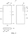
- FIG. 2 is a view illustrating a state in which a second display area of a display is received in a second housing, according to an embodiment of the disclosure.
- FIGS. 2 and 3 illustrate a structure in which the display 203 (e.g., flexible display) is extended to the right when the electronic device 101 is viewed from the front.
- the extending direction of the display 203 is not limited to one direction (e.g., left direction), but design changes may be made so that the display 203 is extendable to the left and/or in two directions.
- the state shown in FIG. 2 may be defined as a first housing 201 being closed with respect to a second housing 202, and the state shown in FIG. 2 may be defined as the first housing 201 being open with respect to the second housing 202.
- the "closed state” or “opened state” may be defined as a closed or opened state of the electronic device.
- the electronic device 101 may include housings 201 and 202.
- the housings 201 and 202 may include a second housing 202 and a first housing 201 movably disposed with respect to the second housing 202.
- the electronic device 101 may be interpreted as having a structure in which the second housing 202 is slidably disposed on the first housing 201.
- the first housing 201 may be disposed to perform reciprocating motion by a predetermined distance in the shown direction with respect to the second housing 202, for example, a direction indicated by the arrow ⁇ .
- the configuration of the electronic device 101 of FIGS. 2 and 3 may be identical in whole or part to the configuration of the electronic device 101 of FIG. 1 .
- the first housing 201 may be referred to as, for example, a first structure, a slide unit, or a slide housing, and may be disposed to reciprocate on the second housing 202.
- the first housing 201 may receive various electrical/electronic components, such as a circuit board or a battery.
- the second housing 202 may be referred to as, e.g., a second structure, a main part, or a main housing, and may guide the movement of the first housing 201.
- a portion (e.g., the first display area A1) of the display 203 may be seated on the first housing 201.
- another portion (e.g., the second display area A2) of the display 203 may be received into the inside of the second housing 202 (e.g., a slide-in motion) or be exposed to the outside of the second housing 202 (e.g., a slide-out motion) as the first housing 201 moves (e.g., slides) with respect to the second housing 202.
- a motor, a speaker, a sim socket, and/or a sub circuit board electrically connected with a main circuit board may be disposed in the first housing 201.
- a main circuit board on which electrical components, such as an application processor (AP) and a communication processor (CP) are mounted may be disposed in the second housing 202.
- AP application processor
- CP communication processor
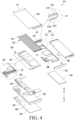
- the supporting structure 213 may be connected with the first housing 201.
- the supporting structure 213 may be positioned between the first plate 211 and the slide cover 212.
- the supporting structure 213 may move with respect to the second housing 202.
- the closed state e.g., FIG. 2
- most of the structure may be received in the second housing 202.
- at least a portion of the supporting structure 213 may move corresponding to the curved surface 250 positioned at the edge of the first housing 201.
- the first plate 211 where the motor 286 is disposed may be slid in, and the outer portion (e.g., a portion other than the protrusion 2152) of the guide rail 215 may push out the upper and/or lower ends of the plurality of bars 214 bent. Accordingly, the expanded display 203 may be received between the first plate 211 and the slide cover 212.
- the second display area A2 of the display 203 may be mounted or supported on the plurality of bars 214 of the supporting structure 213.
- the slide-out state e.g., FIG. 5B
- at least a portion of the second display area A2 may be exposed along with the first display area A1.
- some of the plurality of bars 214 of the supporting structure 213 may substantially form a flat surface, thereby supporting or maintaining the second display area A2 in the flat state.
- the combination of the plurality of bars 214 may be replaced with a bendable integral supporting member (not shown).
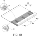
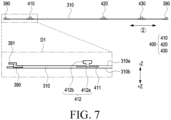
- an electronic device 101 may include a display (e.g., the display 203 of FIG. 4 ), a supporting structure (e.g., the supporting structure 213 of FIGS. 6A and 6B ) supporting the display 203, and a rib structure 400 providing enhanced bending of the display 203.
- the configuration of the supporting structure 213 and the rib structure 400 of FIG. 7 may be identical in whole or part to the configuration of the supporting structure 213 and the rib structure 400 of FIGS. 4 and 6A and 6B .
- an electronic device 101 may include a first housing 201 (e.g., the first plate 211), a second housing 202 (e.g., the second plate 221), a supporting structure 213, a rib structure 400, and various components (e.g., the camera module 249a).
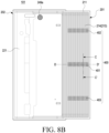
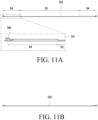
- the configuration of the first housing 201, the second housing 202, the display 203, the supporting structure 213, and the rib structure 400 of FIGS. 8A , 8B , 9 , 10 , 11A, and 11B may be identical in whole or part to the configuration of the first housing 201, the second housing 202, the display 203, the supporting structure 213, and the rib structure 400 of FIGS. 4 , 6A , 6B , and 7 .
- the plurality of bars 214 of the supporting structure 213 may be processed so that the rib structure 400 is formed in a partial area P1 in an area that does not overlap the battery 289.
- thickness machining may be conducted in one area P2 of some bars overlapping the first surface facing the +Z axis of the battery 289 among the plurality of bars 214 of the supporting structure 213.
- the thickness of the battery 289 may be increased as the thickness of some bars in the area P2 is reduced.
- guide ends 390 may be disposed on two opposite ends of the first bar 310.
- the guide ends 390 may slide along a recess-shaped rail (e.g., the rail 2151 of FIG. 4 ) formed in the guide rail (e.g., the guide rail 215 of FIG. 4 ).
- the display (e.g., the display 203 of FIG. 4 ) may be disposed over the first surface 310a (e.g., the surface in the +Z-axis direction) of the first bar 310, and the rib structure 400 for connecting with the first plate 211 may be disposed on the second surface 310b (e.g., the surface in the -Z-axis direction) opposite to the first surface 310a.
- first surface 310a e.g., the surface in the +Z-axis direction
- the rib structure 400 for connecting with the first plate 211 may be disposed on the second surface 310b (e.g., the surface in the -Z-axis direction) opposite to the first surface 310a.
- the first bar 310 may need to be reduced in thickness in the area overlapping the battery.
- the first areas S 1 overlapping the battery may be implemented to be set to have a minimum thickness to support the display 203.
- the first areas S1 may be positioned in an area overlapping the batteries 289a and 289b, and the second areas S2 may be positioned in an area T not overlapping the batteries 289a and 289b.
- the capacity of the battery 289 may be utilized in twice as large a space as the reduction in thickness of the first bar 310.
- the second areas S2 where the plurality of ribs 410 are disposed may require a designated thickness space to fix (e.g., weld) each rib 410 to the first bar 310, the second areas S2 may be formed to be relatively thicker than the first areas S1.
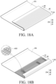
- the second bar 320 (e.g., the A1th array A1 and/or A3th array A3 of FIGS. 18A and 18B ) where no rib structure 400 is disposed may be divided into a third area S3 and a fourth area S4 depending on whether it overlaps an electrical component (e.g., battery).
- the second bar 320 may include a third area S3 overlapping an electrical component and a fourth area S4 not overlapping an electrical component.
- the thickness of the third area S3 for an electrical component to be mounted may be smaller than the thickness of the fourth area S4.
- the thickness of the third area S3 may be about 0.55 mm to 0.65 mm.
- the third bar 330 (e.g., the A1th array A1 and/or the A3th array A3 of FIGS. 18A and 18B ) where no rib structure 400 is disposed may be formed to be overall thin to increase the thickness of an electrical component (e.g., battery 289).
- the third bar 330 may be formed to have a thickness corresponding to the first area S 1 of the first bar 310 where the rib structure 400 is disposed.
- the thickness of the third bar 330 may be about 0.55 mm to 0.65 mm as a whole.
- the thickness of the third bar 330 may be about 0.6 mm overall.
- FIG. 12 is a cross-sectional view illustrating, in another direction, a supporting structure disposed between a display and a first plate in a closed state of an electronic device according to an embodiment of the disclosure.
- FIG. 13 is a cross-sectional view illustrating a portion of a supporting structure disposed between a display and a first plate in a closed state of an electronic device according to an embodiment of the disclosure.
- an electronic device 101 may include a first housing 201 (e.g., the first plate 211 and slide cover 212), a second housing 202 (e.g., the second plate 221 and plate cover 222), a display 203, a supporting structure 213, a rib structure 400, a battery 289 (e.g., the first battery 289a or the second battery 289b) and various components (e.g., the rack 287).
- a first housing 201 e.g., the first plate 211 and slide cover 212
- a second housing 202 e.g., the second plate 221 and plate cover 222
- a display 203 e.g., the second plate 221 and plate cover 222
- a supporting structure 213, a rib structure 400 e.g., the first battery 289a or the second battery 289b
- various components e.g., the rack 287
- the display 203 may switch from the slide-in to slide-out motion, along with the first plate 211.
- the supporting structure 213 is disposed between the display 203 and the first plate 211 to support the sliding motion of the display 203.
- the rib structure 400 coupled with the supporting structure 213 may limit a lift of the display 203 by connecting the first plate 211 and the supporting structure 213 (and display 203).
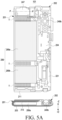
- FIGS. 12 and 13 are cross-sectional views taken along A-A' of FIG. 8A .
- the supporting structure 213 may include a plurality of bars 214, and a rib structure 400 may be disposed on some bars 214 of the plurality of bars 214.
- the rib structure 400 may include a plurality of ribs 410, and the plurality of ribs 410 may be disposed on the partial areas of some bars 214.
- At least a portion of the second plate 221 may have different thicknesses depending on whether it overlaps the battery 289. At least the portion may include a first portion 2211 overlapping the battery 289 and a second portion 2212 not overlapping the battery 289. The thickness of the first portion 2211 may be smaller than the thickness of the second portion 2212.
- the second plate 221 may have a second recess 502 to which at least a portion (e.g., a portion of the battery 289 in the +Z-axis direction) of the battery 289 and the first plate 211 may be inserted.
- the second plate 221 with a recess may lead to an increase the thickness of the battery 289 in the +Z-axis direction, increasing the capacity of the battery.
- the thickness of the battery 289 may be further increased by about 0.4mm.
- At least some bars 214 of the supporting structure 213 may have different thicknesses depending on whether a rib structure 400 is disposed.
- the at least some bars 214 may include a first area S1 in which the rib structure 400 is not disposed and a second area S2 in which the rib structure 400 is disposed.
- the second area S2 may need to be relatively thick as compared with the first area S1.
- the area in which the rib structure 400 is disposed may be adjacent to an edge of the battery 289.
- a plurality of rib structures 400 may be formed.
- rib structures 400 may be disposed between the first battery 289 and the second battery 289, in an area adjacent to an end facing above the battery 289 (e.g., the +Y-axis direction), and in an area adjacent to an end facing below the battery 289 (e.g., the -Y-axis direction).
- two batteries and the rib structures 400 disposed adjacent thereto are described as an example. However, without limitations thereto, various design changes may be made to the arrange of one battery (or three or more batteries) and rib structures 400 adjacent thereto.
- FIG. 14 is a cross-sectional view illustrating a portion of a supporting structure disposed between a display and a first plate in a closed state of an electronic device according to an embodiment of the disclosure.
- an electronic device 101 may include a first housing 201 (e.g., the first plate 211), a second housing 202 (e.g., the second plate 221), a display 203, a supporting structure 213, a rib structure 400, a battery 289 (e.g., the first battery 289a or the second battery 289b) and various components (e.g., the rack 287).
- a first housing 201 e.g., the first plate 211
- a second housing 202 e.g., the second plate 221
- a display 203 e.g., the second plate 221
- a supporting structure 213, a rib structure 400 e.g., the first battery 289a or the second battery 289b
- various components e.g., the rack 287
- the thickness of the supporting structure 213 overlapping the battery 289 may be smaller, the thickness of the battery 289 may be increased.
- the second plate 221 may be manufactured without a change in thickness.
- friction between the first plate 211 and the second plate 221 may be increased in the circled area C1.
- the increased friction may hinder the driving force when the first plate 211 slides.
- only one surface of the battery may be designed to be expandable to reduce hindrance to the driving force.
- FIG. 17B is a cross-sectional view taken along D-D' of FIG. 8B in a closed state of an electronic device according to an embodiment of the disclosure.
- the display 203 may switch from the slide-in to slide-out motion, along with the first plate 211.
- the supporting structure 213 is disposed between the display 203 and the first plate 211 to support the sliding motion of the display 203.
- the rib structure 400 coupled with the supporting structure 213 may limit a lift of the display 203 by connecting the first plate 211 and the supporting structure 213 (and display 203).
- the supporting rib 4102 may be formed in a relatively large size as compared with the guide ribs 4101 disposed on the A2th array A2. Accordingly, at least one bar 214 of the A3th array A3, as compared with the bars 214 of the A2th array A2, may main a stronger coupling to the first plate 211.
- FIG. 20 is a cross-sectional view illustrating another shape of a rib structure and a supporting structure supporting a slide of a display according to an embodiment of the disclosure.
- guide ends 390 may be disposed on two opposite ends of the first bar 310.
- the guide ends 390 may slide along a recess-shaped rail (e.g., the rail 2151 of FIG. 4 ) formed in the guide rail (e.g., the guide rail 215 of FIG. 4 ).
- the first bar 310 may be formed to have different thicknesses depending on areas and, in an area formed with the same thickness, the ribs may be designed in different shapes depending on the spacing between the ribs.
- the second area S2 in which the first rib 410 is positioned may be designed to have a larger thickness than the 1-1th area S11.
- One end portion of the first rib 410 toward a thinner area (e.g., the 1-lth area S11) from the center of the first rib 410 may be longer as compared with the other end portion facing opposite to the one end.
- the one end of the first rib 410 has a length of D1+ ⁇
- the other end of the first rib 410 may have a length of D1.
- the rib structure 400 is disposed only in an area that does not overlap the battery 289, thereby enhancing the mounting space of the battery 289.
- an electronic device may comprise a first housing (e.g., 201 of FIGS. 2 to 4 ), a second housing (e.g., 202 of FIGS. 2 to 4 ), the first housing slidable with respect to the second housing, a flexible display (e.g., 203 of FIG. 4 ) including a first display area and a second display area extending from the first display area and bendable or rollable, a battery (e.g., 289 of FIG. 4 ) disposed in an area of the first housing or the second housing, and a supporting structure (e.g., 213 of FIG.
- a first housing e.g., 201 of FIGS. 2 to 4
- a second housing e.g., 202 of FIGS. 2 to 4
- the first housing slidable with respect to the second housing
- a flexible display e.g., 203 of FIG. 4
- a battery e.g., 289 of FIG. 4
- a supporting structure e.g
- the supporting structure may include a first area (e.g., S 1 of FIG. 13 ) overlapping the battery and a second area (e.g., S2 of FIG. 13 ) extending from the first area.
- the first area of the supporting structure may have a first thickness
- the second area of the supporting structure may have a second thickness larger than the first thickness.
- the electronic device may further comprise a rib structure (e.g., 400 of FIG. 12 ) including a fixing portion (e.g., 411 of FIG. 7 ) coupled with a portion of the supporting structure and a stepped portion (e.g., 412 of FIG. 7 ) extending from the fixing portion to the first housing.
- a rib structure e.g., 400 of FIG. 12
- a fixing portion e.g., 411 of FIG. 7
- a stepped portion e.g., 412 of FIG. 7
- At least some of the plurality of bars may be formed to have a different thickness depending on an area.
- the plurality of bars may include a first bar and a second bar parallel to the first bar.
- the first bar may include the first area and the second area. No rib may be disposed in the first area, and the rib may be disposed in the second area.
- the second bar may be formed to overall have a same thickness as the first area of the first bar.
- the rib structure may be disposed between guide ends disposed on two opposite ends of the first bar.
- the rib structure may comprise a fixing portion configured to be fixed to the bar and a stepped portion extending from the fixing portion.
- At least a portion of the second housing may include a first portion overlapping the battery and a second portion extending from the first portion.
- the first portion (e.g., 2211 of FIG. 12 ) of the second housing may have a third thickness
- the second portion (e.g., 2212 of FIG. 12 ) of the second housing may have a fourth thickness larger than the third thickness.
Landscapes
- Engineering & Computer Science (AREA)
- Theoretical Computer Science (AREA)
- Computer Hardware Design (AREA)
- Physics & Mathematics (AREA)
- General Physics & Mathematics (AREA)
- Human Computer Interaction (AREA)
- General Engineering & Computer Science (AREA)
- Mathematical Physics (AREA)
- Power Engineering (AREA)
- Telephone Set Structure (AREA)
Applications Claiming Priority (3)
| Application Number | Priority Date | Filing Date | Title |
|---|---|---|---|
| KR20210192808 | 2021-12-30 | ||
| KR1020220031879A KR20230103822A (ko) | 2021-12-30 | 2022-03-15 | 플렉서블 디스플레이 및 이를 포함하는 전자 장치 |
| PCT/KR2022/020355 WO2023128408A1 (ko) | 2021-12-30 | 2022-12-14 | 플렉서블 디스플레이 및 이를 포함하는 전자 장치 |
Publications (2)
| Publication Number | Publication Date |
|---|---|
| EP4394548A1 true EP4394548A1 (de) | 2024-07-03 |
| EP4394548A4 EP4394548A4 (de) | 2025-01-15 |
Family
ID=86991543
Family Applications (1)
| Application Number | Title | Priority Date | Filing Date |
|---|---|---|---|
| EP22916552.7A Pending EP4394548A4 (de) | 2021-12-30 | 2022-12-14 | Flexible anzeige und elektronische vorrichtung damit |
Country Status (2)
| Country | Link |
|---|---|
| US (2) | US12443223B2 (de) |
| EP (1) | EP4394548A4 (de) |
Families Citing this family (4)
| Publication number | Priority date | Publication date | Assignee | Title |
|---|---|---|---|---|
| US12259759B2 (en) * | 2019-04-24 | 2025-03-25 | Google Llc | Support device and foldable device having same |
| CN113107957B (zh) * | 2021-03-31 | 2022-07-12 | 深圳市华星光电半导体显示技术有限公司 | 轴体及显示装置 |
| CN115529367B (zh) * | 2021-06-25 | 2025-08-26 | 北京小米移动软件有限公司 | 一种电子设备 |
| WO2026059303A1 (ko) * | 2024-09-10 | 2026-03-19 | 삼성전자 주식회사 | 구동 구조물의 가이드 구조를 포함하는 전자 장치 |
Family Cites Families (34)
| Publication number | Priority date | Publication date | Assignee | Title |
|---|---|---|---|---|
| KR20170116551A (ko) | 2016-04-11 | 2017-10-19 | 박현민 | 연성 디스플레이 패널용 슬라이딩 모듈 |
| EP3489817A4 (de) | 2016-07-19 | 2020-04-08 | Shenzhen Royole Technologies Co., Ltd | Flexible vorrichtung |
| WO2018014196A1 (zh) | 2016-07-19 | 2018-01-25 | 深圳市柔宇科技有限公司 | 柔性装置 |
| WO2019107854A1 (en) * | 2017-11-28 | 2019-06-06 | Samsung Electronics Co., Ltd. | Foldable display device |
| KR102266152B1 (ko) * | 2018-02-22 | 2021-06-17 | 삼성전자주식회사 | 디스플레이 영역의 크기 변경이 가능한 플렉시블 디스플레이를 포함하는 전자 장치 및 그 제어 방법 |
| KR102269604B1 (ko) | 2018-02-23 | 2021-06-28 | 삼성전자주식회사 | 이동 가능한 플렉서블 디스플레이를 포함하는 전자 장치 |
| KR102481292B1 (ko) | 2018-04-13 | 2022-12-26 | 삼성전자주식회사 | 플렉시블 디스플레이를 포함하는 전자 장치 |
| CN111480190B (zh) * | 2018-11-23 | 2022-04-15 | Lg电子株式会社 | 柔性显示装置 |
| KR102834302B1 (ko) | 2019-03-18 | 2025-07-15 | 엘지전자 주식회사 | 롤-슬라이드 이동 단말기 |
| EP3942786B1 (de) | 2019-03-18 | 2024-10-23 | LG Electronics Inc. | Mobiles endgerät |
| KR102754149B1 (ko) | 2019-07-30 | 2025-01-15 | 삼성디스플레이 주식회사 | 표시 장치 및 그것의 제조 방법 |
| KR102331362B1 (ko) | 2019-12-26 | 2021-11-25 | 주식회사 에스코넥 | 레일 유니트를 구비한 아웃 폴딩 모바일 장치 |
| KR102322916B1 (ko) | 2020-01-13 | 2021-11-05 | 주식회사 에스코넥 | 롤러블 모바일 장치 |
| KR102668759B1 (ko) | 2020-04-07 | 2024-05-23 | 엘지전자 주식회사 | 이동 단말기 |
| WO2021246561A1 (ko) | 2020-06-05 | 2021-12-09 | 엘지전자 주식회사 | 이동 단말기 |
| KR20210154719A (ko) | 2020-06-12 | 2021-12-21 | 삼성전자주식회사 | 플렉서블 디스플레이 및 카메라 모듈을 포함하는 전자 장치 |
| WO2022015048A1 (ko) * | 2020-07-14 | 2022-01-20 | 삼성전자 주식회사 | 롤러블 디스플레이를 포함하는 전자 장치 |
| EP4163760B1 (de) * | 2020-07-14 | 2025-03-26 | Samsung Electronics Co., Ltd. | Elektronische vorrichtung mit flexibler anzeige |
| KR102846589B1 (ko) * | 2020-09-18 | 2025-08-14 | 삼성전자 주식회사 | 플렉서블 디스플레이 및 디스플레이 지지 구조를 포함하는 전자 장치, 및 디스플레이 지지 구조의 제조 방법 |
| KR102290231B1 (ko) | 2020-09-28 | 2021-08-20 | 삼성전자주식회사 | 플렉서블 디스플레이를 포함하는 전자 장치 |
| CN116348942A (zh) * | 2020-10-12 | 2023-06-27 | 三星电子株式会社 | 包括柔性显示器的电子装置 |
| KR102274481B1 (ko) | 2020-10-12 | 2021-07-08 | 삼성전자 주식회사 | 플렉서블 디스플레이를 포함하는 전자 장치 |
| WO2022080630A1 (en) * | 2020-10-12 | 2022-04-21 | Samsung Electronics Co., Ltd. | Electronic device including friction reducing structure |
| KR20220060861A (ko) * | 2020-11-05 | 2022-05-12 | 삼성전자주식회사 | 플렉서블 디스플레이를 포함하는 전자 장치 |
| KR102784343B1 (ko) * | 2020-11-05 | 2025-03-21 | 삼성전자 주식회사 | 디스플레이 롤링 가이드 구조를 포함하는 전자 장치 |
| US11935445B2 (en) * | 2020-11-06 | 2024-03-19 | Samsung Electronics Co., Ltd | Electronic device including flexible display and method of operating the same |
| EP4191383A4 (de) * | 2020-11-06 | 2024-01-03 | Samsung Electronics Co., Ltd. | Elektronische vorrichtung mit flexibler anzeige und betriebsverfahren dafür |
| US12008198B2 (en) * | 2020-11-12 | 2024-06-11 | Samsung Electronics Co., Ltd | Electronic device including rollable display |
| WO2022108336A1 (ko) * | 2020-11-18 | 2022-05-27 | 삼성전자 주식회사 | 플렉서블 디스플레이를 포함하는 전자 장치 및 그 동작 방법 |
| WO2022108342A1 (ko) * | 2020-11-18 | 2022-05-27 | 삼성전자 주식회사 | 슬라이딩 구조 및 플렉서블 디스플레이를 포함하는 전자 장치 |
| WO2022119351A1 (ko) * | 2020-12-02 | 2022-06-09 | 삼성전자 주식회사 | 플렉서블 디스플레이를 포함하는 롤러블 전자 장치 |
| WO2022139504A1 (ko) * | 2020-12-23 | 2022-06-30 | 삼성전자 주식회사 | 롤러블 전자 장치 |
| KR20220112603A (ko) * | 2021-02-04 | 2022-08-11 | 삼성전자주식회사 | 연성회로기판 및 이를 포함하는 폴더블 전자 장치 |
| KR20210116380A (ko) | 2021-09-07 | 2021-09-27 | 삼성전자주식회사 | 안테나 및 이를 포함하는 전자 장치 |
-
2022
- 2022-12-14 EP EP22916552.7A patent/EP4394548A4/de active Pending
- 2022-12-27 US US18/146,751 patent/US12443223B2/en active Active
-
2025
- 2025-08-28 US US19/313,206 patent/US20250390139A1/en active Pending
Also Published As
| Publication number | Publication date |
|---|---|
| US20250390139A1 (en) | 2025-12-25 |
| US12443223B2 (en) | 2025-10-14 |
| US20230213967A1 (en) | 2023-07-06 |
| EP4394548A4 (de) | 2025-01-15 |
Similar Documents
| Publication | Publication Date | Title |
|---|---|---|
| EP4394548A1 (de) | Flexible anzeige und elektronische vorrichtung damit | |
| US12457697B2 (en) | Flexible display, structure supporting the flexible display, and electronic device including the same | |
| US12346169B2 (en) | Electronic device including support structure | |
| EP4492190A1 (de) | Aufrollbare elektronische vorrichtung mit mehrstangenstruktur | |
| EP4375791A1 (de) | Elektronische vorrichtung mit antriebsmotor | |
| US12341919B2 (en) | Antenna and electronic device including the same | |
| US12549652B2 (en) | Flexible display and electronic device including the same | |
| US20250267804A1 (en) | Electronic device comprising driving motor | |
| KR20230133745A (ko) | 부품 배치 공간을 고려한 슬라이더블 전자 장치 | |
| US20250140496A1 (en) | Rollable electronic device comprising button structure | |
| US20250008011A1 (en) | Electronic apparatus including antenna | |
| US20240422925A1 (en) | Electronic device comprising driving motor | |
| KR20230103822A (ko) | 플렉서블 디스플레이 및 이를 포함하는 전자 장치 | |
| US20240431048A1 (en) | Rollable electronic device comprising guide assembly | |
| US20250053204A1 (en) | Flexible display assembly and electronic device including same | |
| EP4462227B1 (de) | Aufrollbare elektronische vorrichtung mit mehrstangenstruktur | |
| EP4270909B1 (de) | Elektronische vorrichtung mit antriebsmotor | |
| US20250227171A1 (en) | Electronic device comprising driving motor | |
| US20260089247A1 (en) | Support structure for supporting flexible display, and electronic device comprising same | |
| US20250227170A1 (en) | Electronic device including driving motor | |
| US20250310430A1 (en) | Electronic device comprising retainer | |
| KR102959688B1 (ko) | 안테나 구조 및 이를 포함하는 전자 장치 | |
| EP4535560A1 (de) | Antennenstruktur und elektronische vorrichtung damit | |
| CN118475894A (zh) | 柔性显示器和包括其的电子装置 | |
| KR20240173116A (ko) | 플렉서블 디스플레이를 지지하는 지지 구조 및 이를 포함하는 전자 장치 |
Legal Events
| Date | Code | Title | Description |
|---|---|---|---|
| STAA | Information on the status of an ep patent application or granted ep patent |
Free format text: STATUS: THE INTERNATIONAL PUBLICATION HAS BEEN MADE |
|
| PUAI | Public reference made under article 153(3) epc to a published international application that has entered the european phase |
Free format text: ORIGINAL CODE: 0009012 |
|
| STAA | Information on the status of an ep patent application or granted ep patent |
Free format text: STATUS: REQUEST FOR EXAMINATION WAS MADE |
|
| 17P | Request for examination filed |
Effective date: 20240325 |
|
| AK | Designated contracting states |
Kind code of ref document: A1 Designated state(s): AL AT BE BG CH CY CZ DE DK EE ES FI FR GB GR HR HU IE IS IT LI LT LU LV MC ME MK MT NL NO PL PT RO RS SE SI SK SM TR |
|
| A4 | Supplementary search report drawn up and despatched |
Effective date: 20241212 |
|
| RIC1 | Information provided on ipc code assigned before grant |
Ipc: G09F 9/30 20060101ALI20241206BHEP Ipc: G06F 1/16 20060101AFI20241206BHEP |
|
| DAV | Request for validation of the european patent (deleted) | ||
| DAX | Request for extension of the european patent (deleted) |