EP4394624A1 - Procédé et appareil d'estimation de paramètre d'état de véhicule - Google Patents
Procédé et appareil d'estimation de paramètre d'état de véhicule Download PDFInfo
- Publication number
- EP4394624A1 EP4394624A1 EP21956417.6A EP21956417A EP4394624A1 EP 4394624 A1 EP4394624 A1 EP 4394624A1 EP 21956417 A EP21956417 A EP 21956417A EP 4394624 A1 EP4394624 A1 EP 4394624A1
- Authority
- EP
- European Patent Office
- Prior art keywords
- wheel speed
- preset
- covariance
- measurement
- vehicle
- Prior art date
- Legal status (The legal status is an assumption and is not a legal conclusion. Google has not performed a legal analysis and makes no representation as to the accuracy of the status listed.)
- Pending
Links
Images


Classifications
-
- B—PERFORMING OPERATIONS; TRANSPORTING
- B60—VEHICLES IN GENERAL
- B60W—CONJOINT CONTROL OF VEHICLE SUB-UNITS OF DIFFERENT TYPE OR DIFFERENT FUNCTION; CONTROL SYSTEMS SPECIALLY ADAPTED FOR HYBRID VEHICLES; ROAD VEHICLE DRIVE CONTROL SYSTEMS FOR PURPOSES NOT RELATED TO THE CONTROL OF A PARTICULAR SUB-UNIT
- B60W50/00—Details of control systems for road vehicle drive control not related to the control of a particular sub-unit, e.g. process diagnostic or vehicle driver interfaces
- B60W50/02—Ensuring safety in case of control system failures, e.g. by diagnosing, circumventing or fixing failures
- B60W50/0205—Diagnosing or detecting failures; Failure detection models
-
- B—PERFORMING OPERATIONS; TRANSPORTING
- B60—VEHICLES IN GENERAL
- B60W—CONJOINT CONTROL OF VEHICLE SUB-UNITS OF DIFFERENT TYPE OR DIFFERENT FUNCTION; CONTROL SYSTEMS SPECIALLY ADAPTED FOR HYBRID VEHICLES; ROAD VEHICLE DRIVE CONTROL SYSTEMS FOR PURPOSES NOT RELATED TO THE CONTROL OF A PARTICULAR SUB-UNIT
- B60W40/00—Estimation or calculation of non-directly measurable driving parameters for road vehicle drive control systems not related to the control of a particular sub unit, e.g. by using mathematical models
- B60W40/10—Estimation or calculation of non-directly measurable driving parameters for road vehicle drive control systems not related to the control of a particular sub unit, e.g. by using mathematical models related to vehicle motion
-
- B—PERFORMING OPERATIONS; TRANSPORTING
- B60—VEHICLES IN GENERAL
- B60T—VEHICLE BRAKE CONTROL SYSTEMS OR PARTS THEREOF; BRAKE CONTROL SYSTEMS OR PARTS THEREOF, IN GENERAL; ARRANGEMENT OF BRAKING ELEMENTS ON VEHICLES IN GENERAL; PORTABLE DEVICES FOR PREVENTING UNWANTED MOVEMENT OF VEHICLES; VEHICLE MODIFICATIONS TO FACILITATE COOLING OF BRAKES
- B60T8/00—Arrangements for adjusting wheel-braking force to meet varying vehicular or ground-surface conditions, e.g. limiting or varying distribution of braking force
- B60T8/17—Using electrical or electronic regulation means to control braking
- B60T8/172—Determining control parameters used in the regulation, e.g. by calculations involving measured or detected parameters
-
- B—PERFORMING OPERATIONS; TRANSPORTING
- B60—VEHICLES IN GENERAL
- B60T—VEHICLE BRAKE CONTROL SYSTEMS OR PARTS THEREOF; BRAKE CONTROL SYSTEMS OR PARTS THEREOF, IN GENERAL; ARRANGEMENT OF BRAKING ELEMENTS ON VEHICLES IN GENERAL; PORTABLE DEVICES FOR PREVENTING UNWANTED MOVEMENT OF VEHICLES; VEHICLE MODIFICATIONS TO FACILITATE COOLING OF BRAKES
- B60T8/00—Arrangements for adjusting wheel-braking force to meet varying vehicular or ground-surface conditions, e.g. limiting or varying distribution of braking force
- B60T8/17—Using electrical or electronic regulation means to control braking
- B60T8/1755—Brake regulation specially adapted to control the stability of the vehicle, e.g. taking into account yaw rate or transverse acceleration in a curve
- B60T8/17551—Brake regulation specially adapted to control the stability of the vehicle, e.g. taking into account yaw rate or transverse acceleration in a curve determining control parameters related to vehicle stability used in the regulation, e.g. by calculations involving measured or detected parameters
-
- B—PERFORMING OPERATIONS; TRANSPORTING
- B60—VEHICLES IN GENERAL
- B60W—CONJOINT CONTROL OF VEHICLE SUB-UNITS OF DIFFERENT TYPE OR DIFFERENT FUNCTION; CONTROL SYSTEMS SPECIALLY ADAPTED FOR HYBRID VEHICLES; ROAD VEHICLE DRIVE CONTROL SYSTEMS FOR PURPOSES NOT RELATED TO THE CONTROL OF A PARTICULAR SUB-UNIT
- B60W40/00—Estimation or calculation of non-directly measurable driving parameters for road vehicle drive control systems not related to the control of a particular sub unit, e.g. by using mathematical models
- B60W40/02—Estimation or calculation of non-directly measurable driving parameters for road vehicle drive control systems not related to the control of a particular sub unit, e.g. by using mathematical models related to ambient conditions
- B60W40/06—Road conditions
- B60W40/068—Road friction coefficient
-
- B—PERFORMING OPERATIONS; TRANSPORTING
- B60—VEHICLES IN GENERAL
- B60W—CONJOINT CONTROL OF VEHICLE SUB-UNITS OF DIFFERENT TYPE OR DIFFERENT FUNCTION; CONTROL SYSTEMS SPECIALLY ADAPTED FOR HYBRID VEHICLES; ROAD VEHICLE DRIVE CONTROL SYSTEMS FOR PURPOSES NOT RELATED TO THE CONTROL OF A PARTICULAR SUB-UNIT
- B60W40/00—Estimation or calculation of non-directly measurable driving parameters for road vehicle drive control systems not related to the control of a particular sub unit, e.g. by using mathematical models
- B60W40/10—Estimation or calculation of non-directly measurable driving parameters for road vehicle drive control systems not related to the control of a particular sub unit, e.g. by using mathematical models related to vehicle motion
- B60W40/107—Longitudinal acceleration
-
- B—PERFORMING OPERATIONS; TRANSPORTING
- B60—VEHICLES IN GENERAL
- B60W—CONJOINT CONTROL OF VEHICLE SUB-UNITS OF DIFFERENT TYPE OR DIFFERENT FUNCTION; CONTROL SYSTEMS SPECIALLY ADAPTED FOR HYBRID VEHICLES; ROAD VEHICLE DRIVE CONTROL SYSTEMS FOR PURPOSES NOT RELATED TO THE CONTROL OF A PARTICULAR SUB-UNIT
- B60W40/00—Estimation or calculation of non-directly measurable driving parameters for road vehicle drive control systems not related to the control of a particular sub unit, e.g. by using mathematical models
- B60W40/10—Estimation or calculation of non-directly measurable driving parameters for road vehicle drive control systems not related to the control of a particular sub unit, e.g. by using mathematical models related to vehicle motion
- B60W40/109—Lateral acceleration
-
- G—PHYSICS
- G06—COMPUTING OR CALCULATING; COUNTING
- G06N—COMPUTING ARRANGEMENTS BASED ON SPECIFIC COMPUTATIONAL MODELS
- G06N3/00—Computing arrangements based on biological models
- G06N3/02—Neural networks
-
- G—PHYSICS
- G06—COMPUTING OR CALCULATING; COUNTING
- G06N—COMPUTING ARRANGEMENTS BASED ON SPECIFIC COMPUTATIONAL MODELS
- G06N3/00—Computing arrangements based on biological models
- G06N3/02—Neural networks
- G06N3/08—Learning methods
-
- B—PERFORMING OPERATIONS; TRANSPORTING
- B60—VEHICLES IN GENERAL
- B60W—CONJOINT CONTROL OF VEHICLE SUB-UNITS OF DIFFERENT TYPE OR DIFFERENT FUNCTION; CONTROL SYSTEMS SPECIALLY ADAPTED FOR HYBRID VEHICLES; ROAD VEHICLE DRIVE CONTROL SYSTEMS FOR PURPOSES NOT RELATED TO THE CONTROL OF A PARTICULAR SUB-UNIT
- B60W50/00—Details of control systems for road vehicle drive control not related to the control of a particular sub-unit, e.g. process diagnostic or vehicle driver interfaces
- B60W2050/0001—Details of the control system
- B60W2050/0019—Control system elements or transfer functions
- B60W2050/0028—Mathematical models, e.g. for simulation
- B60W2050/0031—Mathematical model of the vehicle
-
- B—PERFORMING OPERATIONS; TRANSPORTING
- B60—VEHICLES IN GENERAL
- B60W—CONJOINT CONTROL OF VEHICLE SUB-UNITS OF DIFFERENT TYPE OR DIFFERENT FUNCTION; CONTROL SYSTEMS SPECIALLY ADAPTED FOR HYBRID VEHICLES; ROAD VEHICLE DRIVE CONTROL SYSTEMS FOR PURPOSES NOT RELATED TO THE CONTROL OF A PARTICULAR SUB-UNIT
- B60W50/00—Details of control systems for road vehicle drive control not related to the control of a particular sub-unit, e.g. process diagnostic or vehicle driver interfaces
- B60W50/02—Ensuring safety in case of control system failures, e.g. by diagnosing, circumventing or fixing failures
- B60W50/0205—Diagnosing or detecting failures; Failure detection models
- B60W2050/021—Means for detecting failure or malfunction
-
- B—PERFORMING OPERATIONS; TRANSPORTING
- B60—VEHICLES IN GENERAL
- B60W—CONJOINT CONTROL OF VEHICLE SUB-UNITS OF DIFFERENT TYPE OR DIFFERENT FUNCTION; CONTROL SYSTEMS SPECIALLY ADAPTED FOR HYBRID VEHICLES; ROAD VEHICLE DRIVE CONTROL SYSTEMS FOR PURPOSES NOT RELATED TO THE CONTROL OF A PARTICULAR SUB-UNIT
- B60W50/00—Details of control systems for road vehicle drive control not related to the control of a particular sub-unit, e.g. process diagnostic or vehicle driver interfaces
- B60W50/02—Ensuring safety in case of control system failures, e.g. by diagnosing, circumventing or fixing failures
- B60W50/0205—Diagnosing or detecting failures; Failure detection models
- B60W2050/0215—Sensor drifts or sensor failures
-
- B—PERFORMING OPERATIONS; TRANSPORTING
- B60—VEHICLES IN GENERAL
- B60W—CONJOINT CONTROL OF VEHICLE SUB-UNITS OF DIFFERENT TYPE OR DIFFERENT FUNCTION; CONTROL SYSTEMS SPECIALLY ADAPTED FOR HYBRID VEHICLES; ROAD VEHICLE DRIVE CONTROL SYSTEMS FOR PURPOSES NOT RELATED TO THE CONTROL OF A PARTICULAR SUB-UNIT
- B60W2520/00—Input parameters relating to overall vehicle dynamics
- B60W2520/10—Longitudinal speed
- B60W2520/105—Longitudinal acceleration
-
- B—PERFORMING OPERATIONS; TRANSPORTING
- B60—VEHICLES IN GENERAL
- B60W—CONJOINT CONTROL OF VEHICLE SUB-UNITS OF DIFFERENT TYPE OR DIFFERENT FUNCTION; CONTROL SYSTEMS SPECIALLY ADAPTED FOR HYBRID VEHICLES; ROAD VEHICLE DRIVE CONTROL SYSTEMS FOR PURPOSES NOT RELATED TO THE CONTROL OF A PARTICULAR SUB-UNIT
- B60W2520/00—Input parameters relating to overall vehicle dynamics
- B60W2520/12—Lateral speed
- B60W2520/125—Lateral acceleration
-
- B—PERFORMING OPERATIONS; TRANSPORTING
- B60—VEHICLES IN GENERAL
- B60W—CONJOINT CONTROL OF VEHICLE SUB-UNITS OF DIFFERENT TYPE OR DIFFERENT FUNCTION; CONTROL SYSTEMS SPECIALLY ADAPTED FOR HYBRID VEHICLES; ROAD VEHICLE DRIVE CONTROL SYSTEMS FOR PURPOSES NOT RELATED TO THE CONTROL OF A PARTICULAR SUB-UNIT
- B60W2520/00—Input parameters relating to overall vehicle dynamics
- B60W2520/14—Yaw
-
- B—PERFORMING OPERATIONS; TRANSPORTING
- B60—VEHICLES IN GENERAL
- B60W—CONJOINT CONTROL OF VEHICLE SUB-UNITS OF DIFFERENT TYPE OR DIFFERENT FUNCTION; CONTROL SYSTEMS SPECIALLY ADAPTED FOR HYBRID VEHICLES; ROAD VEHICLE DRIVE CONTROL SYSTEMS FOR PURPOSES NOT RELATED TO THE CONTROL OF A PARTICULAR SUB-UNIT
- B60W2520/00—Input parameters relating to overall vehicle dynamics
- B60W2520/20—Sideslip angle
-
- B—PERFORMING OPERATIONS; TRANSPORTING
- B60—VEHICLES IN GENERAL
- B60W—CONJOINT CONTROL OF VEHICLE SUB-UNITS OF DIFFERENT TYPE OR DIFFERENT FUNCTION; CONTROL SYSTEMS SPECIALLY ADAPTED FOR HYBRID VEHICLES; ROAD VEHICLE DRIVE CONTROL SYSTEMS FOR PURPOSES NOT RELATED TO THE CONTROL OF A PARTICULAR SUB-UNIT
- B60W2520/00—Input parameters relating to overall vehicle dynamics
- B60W2520/28—Wheel speed
-
- B—PERFORMING OPERATIONS; TRANSPORTING
- B60—VEHICLES IN GENERAL
- B60W—CONJOINT CONTROL OF VEHICLE SUB-UNITS OF DIFFERENT TYPE OR DIFFERENT FUNCTION; CONTROL SYSTEMS SPECIALLY ADAPTED FOR HYBRID VEHICLES; ROAD VEHICLE DRIVE CONTROL SYSTEMS FOR PURPOSES NOT RELATED TO THE CONTROL OF A PARTICULAR SUB-UNIT
- B60W2540/00—Input parameters relating to occupants
- B60W2540/18—Steering angle
-
- B—PERFORMING OPERATIONS; TRANSPORTING
- B60—VEHICLES IN GENERAL
- B60W—CONJOINT CONTROL OF VEHICLE SUB-UNITS OF DIFFERENT TYPE OR DIFFERENT FUNCTION; CONTROL SYSTEMS SPECIALLY ADAPTED FOR HYBRID VEHICLES; ROAD VEHICLE DRIVE CONTROL SYSTEMS FOR PURPOSES NOT RELATED TO THE CONTROL OF A PARTICULAR SUB-UNIT
- B60W2552/00—Input parameters relating to infrastructure
- B60W2552/40—Coefficient of friction
Definitions
- This application relates to the field of automotive control technologies, and in particular, to a vehicle status parameter estimation method and apparatus.
- vehicle control systems including an electronic stability program (electronic stability program, ESP), an antilock brake system (antilock brake system, ABS), and a traction control system (traction control system, TCS) have been more widely used in vehicles.
- electronic stability program electronic stability program
- antilock brake system antilock brake system
- ABS traction control system
- TCS traction control system
- various types of vehicle status data usually need to be collected to invoke the various vehicle control systems.
- various sensors may be installed on the vehicles, to collect the vehicle status data.
- some vehicle status data including a centroid sideslip angle usually needs to be measured by installing additional expensive sensors.
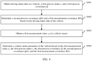
- the determining a first measurement covariance R ( k ) based on the driving status data of the vehicle includes:
- the determining the first measurement covariance R ( k ) based on the road adhesion coefficient ⁇ includes:
- a result obtained by introducing another estimation method for example, a kinematics-based status estimation, a neural network-based status estimation, and a vision-based status estimation
- another estimation method for example, a kinematics-based status estimation, a neural network-based status estimation, and a vision-based status estimation
- the measurement value obtained through measurement of the real sensor and the calculated measurement covariance are extended, and the extended measurement value and measurement covariance are used for the vehicle status estimation. This can further improve the estimation precision of the vehicle status parameter.
- the processing unit is configured to:
- the vehicle status parameter includes one or more of the following: the longitudinal speed v x , the horizontal speed v y , the yaw angular velocity r, the front left wheel speed ⁇ FL , the front right wheel speed ⁇ FR , the rear left wheel speed ⁇ RL , the rear right wheel speed ⁇ RR , the road adhesion coefficient ⁇ , the longitudinal acceleration a x , the horizontal acceleration a y , or the centroid sideslip angle ⁇ .
- this application provides a computer program product including instructions.
- the computer program product includes computer program code, and when the computer program code is run on a computer, the method according to any implementation of the first aspect is performed.
- a horizontal vehicle speed is obtained through estimation based on the yaw angular velocity and the lateral acceleration
- a vertical force and a lateral force are separately obtained through estimation based on the lateral acceleration
- a longitudinal force and the like are obtained through estimation based on the lateral acceleration and the master cylinder pressure value.
- a sideslip angle is obtained through estimation based on the longitudinal vehicle speed obtained in the first estimation and the horizontal vehicle speed obtained in the third estimation
- a road adhesion coefficient and the like are obtained through estimation based on the vertical force, the lateral force, and the longitudinal force obtained in the third estimation.
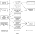
- FIG. 2 is a schematic diagram of a vehicle status estimation based on a plurality of sensors according to an embodiment of this application.
- SAS steering angle sensor
- IMU inertial measurement unit
- MPS master cylinder pressure sensor
- a centroid sideslip angle and a road adhesion coefficient of a vehicle need to be obtained through two estimations.
- Estimation precision of the centroid sideslip angle and the road adhesion coefficient can be improved by reducing a quantity of estimations.
- MPS measurement values Parameters such as a master cylinder pressure value that are obtained through measurement based on the MPS are briefly referred to as MPS measurement values for ease of description.
- a longitudinal vehicle speed may be obtained through estimation based on the WSS measurement values
- a horizontal vehicle speed may be obtained through estimation based on the SAS measurement value and the IMU measurement values
- a road bank angle, a slope, a vertical force, a lateral force, and the like may be separately obtained through estimation based on the IMU measurement values
- a longitudinal force and the like are obtained through estimation based on the MPS measurement value.
- the (3) UKF vehicle status estimation module uses an unscented Kalman filter method to comprehensively estimate a vehicle status, for example, a vehicle speed, a centroid sideslip angle, a tire force, a slip ratio, a tire sideslip angle.
- This module mainly includes the following five sub-modules: a sigma points generation sub-module, a sigma points unscented transformation sub-module, a prior estimation sub-module, a posterior estimation sub-module, and an output model sub-module.
- a sigma points generation sub-module mainly includes the following five sub-modules: a sigma points generation sub-module, a sigma points unscented transformation sub-module, a prior estimation sub-module, a posterior estimation sub-module, and an output model sub-module.
- For functions of the five sub-modules refer to description of steps in a process shown in FIG. 4 , and details are not described herein.
- the driving status data of the vehicle may include environment information and motion status information of the vehicle during vehicle running.
- q v x represents a process covariance coefficient corresponding to the longitudinal speed.
- q v y represents a process covariance coefficient corresponding to the horizontal speed.
- q r represents a process covariance coefficient corresponding to the yaw angular velocity.
- q ⁇ FL represents a process covariance coefficient corresponding to the front left wheel speed.
- q ⁇ FR represents a process covariance coefficient corresponding to the front right wheel speed.
- q ⁇ RL represents a process covariance coefficient corresponding to the rear left wheel speed.
- q ⁇ RR represents a process covariance coefficient corresponding to the front right wheel speed,
- q ⁇ represents a process covariance coefficient corresponding to the road adhesion coefficient.
- the second process covariance Q ( k ) and the first measurement covariance R ( k ) are determined based on the driving status data of the vehicle.
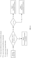
- the determining the second process covariance Q(k) based on the driving status data of the vehicle may be understood as: when the road adhesion coefficient ⁇ is greater than or equal to a first preset road adhesion coefficient threshold ⁇ TH , and an absolute value
- FIG. 5 is a schematic diagram of determining a second process covariance Q ( k ) based on driving status data according to an embodiment of this application.
- a specified road adhesion coefficient threshold namely, the first preset road adhesion coefficient threshold ⁇ TH
- the second process covariance Q ( k ) may be the first preset process covariance matrix.
- the second process covariance Q ( k ) is Q 3( k ).
- the second process covariance Q ( k ) is no longer Q 3( k ).
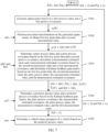
- k ) satisfies: P ⁇ x , y k + 1
- k ⁇ i k + 1
- posterior estimation is performed on the process status and the process covariance based on the Kalman feedback gain matrix K(k + 1
- the posterior process covariance P ⁇ ( k + 1) is a process covariance at the moment k+1 that is obtained through prediction.
- the posterior process status x ⁇ ( k + 1) is a process status at the moment k+1 that is obtained through prediction.
- the transceiver unit 801 is configured to obtain driving status data of a vehicle, a first process status x, and a first process covariance Q.
- the driving status data includes one or more of the following: a lateral acceleration change rate rV, a steering wheel speed ⁇ , a horizontal acceleration a y , a road adhesion coefficient ⁇ , a front left wheel speed ⁇ FL , a front right wheel speed ⁇ FR , a rear left wheel speed ⁇ RL , or a rear right wheel speed ⁇ RR .
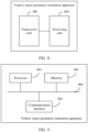
- FIG. 9 is a schematic diagram of a structure of another vehicle status parameter estimation apparatus according to an embodiment of this application.
- the vehicle status parameter estimation apparatus includes a processor 901, a communication interface 902, and a memory 903.
- the processor 901, the communication interface 902, and the memory 903 are coupled through a bus 904.
- An embodiment of this application further provides a computer storage medium, which may be configured to store computer software instructions used by the vehicle status parameter estimation apparatus in the embodiments shown in FIG. 4 to FIG. 7 .
- the computer software instructions include a program designed for the vehicle status parameter estimation apparatus in the foregoing embodiments.
- the storage medium includes but is not limited to a flash memory, a hard disk drive, or a solid-state drive.
- An embodiment of this application further provides a system applied to self-driving or intelligent driving.
- the system includes at least one vehicle status parameter estimation apparatus mentioned in the foregoing embodiment of this application and at least one of other sensors such as a camera and a radar.
- At least one apparatus in the system may be integrated as an entire system or a device, or at least one apparatus in the system may be independently disposed as an element or an apparatus.
- sequence adjustment, combination, and deletion may be performed on the steps in the method embodiments of this application based on an actual requirement.
- Modules in the apparatus embodiments of this application may be combined, divided, or deleted based on an actual requirement.
- sequence numbers of the foregoing processes do not mean execution sequences in various embodiments of this application.
- the execution sequences of the processes should be determined based on functions and internal logic of the processes, and should not be construed as any limitation on the implementation processes of embodiments of this application.
Landscapes
- Engineering & Computer Science (AREA)
- Physics & Mathematics (AREA)
- Mechanical Engineering (AREA)
- Transportation (AREA)
- Automation & Control Theory (AREA)
- Mathematical Physics (AREA)
- Theoretical Computer Science (AREA)
- Biomedical Technology (AREA)
- General Physics & Mathematics (AREA)
- Evolutionary Computation (AREA)
- General Health & Medical Sciences (AREA)
- Molecular Biology (AREA)
- Computing Systems (AREA)
- General Engineering & Computer Science (AREA)
- Data Mining & Analysis (AREA)
- Computational Linguistics (AREA)
- Software Systems (AREA)
- Biophysics (AREA)
- Artificial Intelligence (AREA)
- Life Sciences & Earth Sciences (AREA)
- Health & Medical Sciences (AREA)
- Human Computer Interaction (AREA)
- Control Of Driving Devices And Active Controlling Of Vehicle (AREA)
Applications Claiming Priority (1)
| Application Number | Priority Date | Filing Date | Title |
|---|---|---|---|
| PCT/CN2021/117746 WO2023035234A1 (fr) | 2021-09-10 | 2021-09-10 | Procédé et appareil d'estimation de paramètre d'état de véhicule |
Publications (2)
| Publication Number | Publication Date |
|---|---|
| EP4394624A1 true EP4394624A1 (fr) | 2024-07-03 |
| EP4394624A4 EP4394624A4 (fr) | 2024-10-23 |
Family
ID=85506984
Family Applications (1)
| Application Number | Title | Priority Date | Filing Date |
|---|---|---|---|
| EP21956417.6A Pending EP4394624A4 (fr) | 2021-09-10 | 2021-09-10 | Procédé et appareil d'estimation de paramètre d'état de véhicule |
Country Status (4)
| Country | Link |
|---|---|
| US (1) | US20240208516A1 (fr) |
| EP (1) | EP4394624A4 (fr) |
| CN (1) | CN116134436A (fr) |
| WO (1) | WO2023035234A1 (fr) |
Families Citing this family (2)
| Publication number | Priority date | Publication date | Assignee | Title |
|---|---|---|---|---|
| CN117901841B (zh) * | 2024-02-27 | 2025-08-22 | 大陆软件系统开发中心(重庆)有限公司 | 车辆横摆力矩的补偿方法及装置 |
| CN118839260B (zh) * | 2024-06-27 | 2025-03-18 | 南京航空航天大学 | 飞行器故障诊断方法、模型训练方法、装置和计算机设备 |
Family Cites Families (8)
| Publication number | Priority date | Publication date | Assignee | Title |
|---|---|---|---|---|
| US5094213A (en) * | 1991-02-12 | 1992-03-10 | General Motors Corporation | Method for predicting R-step ahead engine state measurements |
| CN105549003A (zh) * | 2015-12-02 | 2016-05-04 | 华域汽车系统股份有限公司 | 一种汽车雷达目标跟踪方法 |
| KR101786237B1 (ko) * | 2015-12-09 | 2017-10-17 | 현대자동차주식회사 | 운전자보조시스템용 센서의 고장진단 및 보정을 위한 장치 및 방법 |
| DE102016214064A1 (de) * | 2016-07-29 | 2018-02-01 | Zf Friedrichshafen Ag | Bestimmung von Fahrzustandsgrößen |
| CN106515740B (zh) * | 2016-11-14 | 2018-10-09 | 江苏大学 | 基于icdkf的分布式电驱动汽车行驶状态参数估计算法 |
| CN108357498B (zh) * | 2018-02-07 | 2019-12-27 | 北京新能源汽车股份有限公司 | 一种车辆状态参数确定方法、装置及汽车 |
| CN111152795B (zh) * | 2020-01-08 | 2022-12-13 | 东南大学 | 一种基于模型和参数动态调整的自适应车辆状态预测系统及预测方法 |
| CN112665593B (zh) * | 2020-12-17 | 2024-01-26 | 北京经纬恒润科技股份有限公司 | 一种车辆定位方法及装置 |
-
2021
- 2021-09-10 WO PCT/CN2021/117746 patent/WO2023035234A1/fr not_active Ceased
- 2021-09-10 CN CN202180007700.1A patent/CN116134436A/zh active Pending
- 2021-09-10 EP EP21956417.6A patent/EP4394624A4/fr active Pending
-
2024
- 2024-03-08 US US18/600,374 patent/US20240208516A1/en active Pending
Also Published As
| Publication number | Publication date |
|---|---|
| US20240208516A1 (en) | 2024-06-27 |
| EP4394624A4 (fr) | 2024-10-23 |
| CN116134436A (zh) | 2023-05-16 |
| WO2023035234A1 (fr) | 2023-03-16 |
Similar Documents
| Publication | Publication Date | Title |
|---|---|---|
| US20210269018A1 (en) | Vehicle stability control method and device | |
| EP3600985B1 (fr) | Système et procédé d'étalonnage de pneu de véhicule | |
| EP3484755B1 (fr) | Procédé et système de commande de véhicule | |
| US7184868B2 (en) | Vehicle dynamics behavior reproduction system | |
| US20240208516A1 (en) | Vehicle status parameter estimation method and apparatus | |
| US11893004B2 (en) | Anomaly detection in multidimensional sensor data | |
| US6658342B1 (en) | Vehicle stability control | |
| CN114670855B (zh) | 一种确定车辆质量方法、装置、设备及介质 | |
| CN111547059A (zh) | 一种分布式驱动电动汽车惯性参数估计方法 | |
| CN114043986B (zh) | 一种考虑质量失配的轮胎路面附着系数多模型融合估计方法 | |
| CN115848383B (zh) | 基于gps、imu和轮速传感器信号的车速融合估计方法及装置 | |
| KR102863496B1 (ko) | 타이어 코너링 스티프니스 추정 방법, 타이어 코너링 스티프니스 추정값을 이용한 노면 상태 검출 방법, 및 이들을 수행하는 장치 | |
| CN114506333A (zh) | 路面附着系数确定方法、装置、设备以及自动驾驶车辆 | |
| US20190337522A1 (en) | Determining vehicle driving behavior | |
| KR20180138324A (ko) | 차로 유지 제어 장치 및 방법 | |
| US11403441B2 (en) | Method for checking a vehicle dynamics model | |
| EP4197821B1 (fr) | Système et procédé d'estimation de rigidité de pneu | |
| CN117698759A (zh) | 用于紧急避障的迭代轨迹重新规划 | |
| US6216061B1 (en) | Method for determining a reference magnitude | |
| EP4663500A1 (fr) | Système et procédé de commande à châssis intégré, et dispositif, support et produit programme | |
| Junqueira et al. | A model-less approach for estimating vehicles sideslip angle by a neural network concept | |
| Sen et al. | Estimation of vehicle yaw rate and lateral motion for dynamic stability control using unscented Kalman filtering (UKF) approach | |
| Rock et al. | Validating GPS based measurements for vehicle control | |
| CN118457601A (zh) | 附着系数和轮端压力估计方法、装置、设备和介质 | |
| CN116279508A (zh) | 基于快速收敛sckf和自适应轮胎刚度的路面附着系数估计方法及介质 |
Legal Events
| Date | Code | Title | Description |
|---|---|---|---|
| STAA | Information on the status of an ep patent application or granted ep patent |
Free format text: STATUS: THE INTERNATIONAL PUBLICATION HAS BEEN MADE |
|
| PUAI | Public reference made under article 153(3) epc to a published international application that has entered the european phase |
Free format text: ORIGINAL CODE: 0009012 |
|
| STAA | Information on the status of an ep patent application or granted ep patent |
Free format text: STATUS: REQUEST FOR EXAMINATION WAS MADE |
|
| 17P | Request for examination filed |
Effective date: 20240326 |
|
| AK | Designated contracting states |
Kind code of ref document: A1 Designated state(s): AL AT BE BG CH CY CZ DE DK EE ES FI FR GB GR HR HU IE IS IT LI LT LU LV MC MK MT NL NO PL PT RO RS SE SI SK SM TR |
|
| A4 | Supplementary search report drawn up and despatched |
Effective date: 20240920 |
|
| RIC1 | Information provided on ipc code assigned before grant |
Ipc: B60W 50/00 20060101ALI20240916BHEP Ipc: B60T 8/1755 20060101ALI20240916BHEP Ipc: B60T 8/172 20060101ALI20240916BHEP Ipc: B60W 40/10 20120101ALI20240916BHEP Ipc: G06F 18/00 20230101AFI20240916BHEP |
|
| DAV | Request for validation of the european patent (deleted) | ||
| DAX | Request for extension of the european patent (deleted) | ||
| RAP1 | Party data changed (applicant data changed or rights of an application transferred) |
Owner name: SHENZHEN YINWANG INTELLIGENTTECHNOLOGIES CO., LTD. |
|
| GRAP | Despatch of communication of intention to grant a patent |
Free format text: ORIGINAL CODE: EPIDOSNIGR1 |
|
| STAA | Information on the status of an ep patent application or granted ep patent |
Free format text: STATUS: GRANT OF PATENT IS INTENDED |
|
| RIC1 | Information provided on ipc code assigned before grant |
Ipc: G06F 18/00 20230101AFI20260128BHEP Ipc: B60W 40/10 20120101ALI20260128BHEP Ipc: B60T 8/172 20060101ALI20260128BHEP Ipc: B60T 8/1755 20060101ALI20260128BHEP Ipc: B60W 50/00 20060101ALI20260128BHEP |
|
| INTG | Intention to grant announced |
Effective date: 20260217 |