EP4394896A1 - Procédé et dispositif de fabrication d'un panneau photovoltaïque comprenant un agencement de cellules solaires par moulage par injection-compression - Google Patents
Procédé et dispositif de fabrication d'un panneau photovoltaïque comprenant un agencement de cellules solaires par moulage par injection-compression Download PDFInfo
- Publication number
- EP4394896A1 EP4394896A1 EP22217402.1A EP22217402A EP4394896A1 EP 4394896 A1 EP4394896 A1 EP 4394896A1 EP 22217402 A EP22217402 A EP 22217402A EP 4394896 A1 EP4394896 A1 EP 4394896A1
- Authority
- EP
- European Patent Office
- Prior art keywords
- moulding
- label
- photovoltaic
- polymer mass
- cavity
- Prior art date
- Legal status (The legal status is an assumption and is not a legal conclusion. Google has not performed a legal analysis and makes no representation as to the accuracy of the status listed.)
- Withdrawn
Links
Images


Classifications
-
- H—ELECTRICITY
- H10—SEMICONDUCTOR DEVICES; ELECTRIC SOLID-STATE DEVICES NOT OTHERWISE PROVIDED FOR
- H10F—INORGANIC SEMICONDUCTOR DEVICES SENSITIVE TO INFRARED RADIATION, LIGHT, ELECTROMAGNETIC RADIATION OF SHORTER WAVELENGTH OR CORPUSCULAR RADIATION
- H10F19/00—Integrated devices, or assemblies of multiple devices, comprising at least one photovoltaic cell covered by group H10F10/00, e.g. photovoltaic modules
- H10F19/80—Encapsulations or containers for integrated devices, or assemblies of multiple devices, having photovoltaic cells
-
- B—PERFORMING OPERATIONS; TRANSPORTING
- B29—WORKING OF PLASTICS; WORKING OF SUBSTANCES IN A PLASTIC STATE IN GENERAL
- B29C—SHAPING OR JOINING OF PLASTICS; SHAPING OF MATERIAL IN A PLASTIC STATE, NOT OTHERWISE PROVIDED FOR; AFTER-TREATMENT OF THE SHAPED PRODUCTS, e.g. REPAIRING
- B29C45/00—Injection moulding, i.e. forcing the required volume of moulding material through a nozzle into a closed mould; Apparatus therefor
- B29C45/14—Injection moulding, i.e. forcing the required volume of moulding material through a nozzle into a closed mould; Apparatus therefor incorporating preformed parts or layers, e.g. injection moulding around inserts or for coating articles
- B29C45/14778—Injection moulding, i.e. forcing the required volume of moulding material through a nozzle into a closed mould; Apparatus therefor incorporating preformed parts or layers, e.g. injection moulding around inserts or for coating articles the article consisting of a material with particular properties, e.g. porous, brittle
-
- B—PERFORMING OPERATIONS; TRANSPORTING
- B29—WORKING OF PLASTICS; WORKING OF SUBSTANCES IN A PLASTIC STATE IN GENERAL
- B29C—SHAPING OR JOINING OF PLASTICS; SHAPING OF MATERIAL IN A PLASTIC STATE, NOT OTHERWISE PROVIDED FOR; AFTER-TREATMENT OF THE SHAPED PRODUCTS, e.g. REPAIRING
- B29C45/00—Injection moulding, i.e. forcing the required volume of moulding material through a nozzle into a closed mould; Apparatus therefor
- B29C45/17—Component parts, details or accessories; Auxiliary operations
- B29C45/46—Means for plasticising or homogenising the moulding material or forcing it into the mould
- B29C45/56—Means for plasticising or homogenising the moulding material or forcing it into the mould using mould parts movable during or after injection, e.g. injection-compression moulding
- B29C45/561—Injection-compression moulding
Definitions
- PV cells may also be referred to as solar cells.
- a body panel of a vehicle including an integrated PV module may be referred to herein as PV integrated car body panel.
- PV panels are typically produced by providing planar, rigid, wafer-based solar cells and then laminating these solar cells between a front side glass sheet and a rear side support structure such as another glass sheet or a metal sheet. Therein, the solar cells are interposed between thin lamination foils serving for both, tightly encapsulating the solar cells and mechanically interconnecting the stack including the front and rear side sheets with the interposed solar cell arrangement.
- PV panels are also referred to as PV modules and typically have a planar structure. These PV panels are well suited for installation on buildings or in solar farms. However, such planar PV panels are hardly suited for an integration into curved surfaces such as for example surfaces of body panels of a car or another vehicle.
- the panel or, specifically, the car body panel including the solar cell arrangement may be regarded as a PV module having a non-planar shape.
- the core side moulding half may also be regarded or referred to as the moving moulding half of the moulding device, and the cavity side moulding half may be regarded or referred to as the fixed moulding half of the moulding device. Therefore, for opening or closing the moulding device, the core side moulding half is either moved towards the cavity side moulding half or away from it, in particular, during the closing procedure, the core side moulding half is moved towards the cavity side moulding half up to a predetermined point or closing state, whereas during the opening procedure of the moulding device, the core side moulding half is moved away from the cavity side moulding half.
- the whole procedure takes place vice versa, if the core side moulding half is the fixed moulding half and the cavity side moulding half is the moving moulding half. Then, for the opening procedure, the cavity side moulding half will be moved away from the core side moulding half and for the closing procedure, the cavity side mould half will be moved towards the core side mould half.
- the moulding device is configured for implementing the method according to an embodiment of the first aspect of the invention.
- thermoplastic polymer is typically injected into a cavity comprised in a mould, such injection being applied with very high pressures.
- thermoplastic polymer may exert an excessive pressure and/or local pressure peaks onto the solar cells in the PV label, thereby inducing a risk of solar cell breakage.
- PV-integrated (car body or other, as a panel for buildings or the like) panel comprising multiple PV cells which are prepared based on brittle semiconductor wafers.
- the PV cells may be, for example, solar cells being fabricated based on crystalline silicon wafers.
- Such wafer-based Si-PV cells may generally have e.g. a high efficiency of more than 15% (i.e. e.g. between 17% and 26%) and a high reliability.
- the sticky viscous or even partially molten polymer material of both encapsulation foils may combine in regions where the foils contact each other and/or may glue to solar cells interposed between the encapsulation foils. Accordingly, upon cooling down and solidifying the polymer material, the solar cells and the polymer material of the lamination foils may form an encapsulation.
- the solar cell arrangement in its encapsulation is generally very fragile
- the solar cell arrangement including the solar cells, the electric connections and the encapsulation is reinforced by one or more stabilisation foils for forming a PV label.
- a front side polymeric stabilisation foil and a rear side polymeric stabilisation foil may enclose the interposed solar cell arrangement and may form a substrate and a superstrate, respectively, prior to reinforcing the PV label by moulding the support structure.
- the PV label may not necessarily comprise the rear side polymeric stabilisation foil.
- the one or more polymeric stabilisation foils may have a thickness of typically between 250 ⁇ m and 2500 ⁇ m.
- the polymeric stabilisation foils may be made with various polymeric materials such as, polycarbonate (PC), polyethylenterephthalat (PET), polyamide (PA), polyetheretherketone (PEEK), Acrylonitrile butadiene styrene (ABS), Polymethyl methacrylate) (PMMA), Polyvinylchlorid (PVC) or a mix of them.
- PC polycarbonate
- PET polyethylenterephthalat
- PA polyamide
- PEEK polyetheretherketone
- ABS Acrylonitrile butadiene styrene
- PMMA Polymethyl methacrylate
- PVC Polyvinylchlorid
- At least the front side stabilisation foil as well as the front side lamination foil shall consist of an optically translucent or transparent material.
- a material forming the stabilisation foil may be a thermoplastic material, i.e.
- the front side polymeric stabilisation foil, the rear side polymeric stabilisation foil and the PV cells may be joined together by an application of heat and/or a lamination process.
- these stacked layers may be interconnected by mechanically joining with each other.
- Such joining may be induced for example by applying sufficient heat to the stack such that the polymeric material of the polymeric foils becomes viscous and/or sticky.
- the polymeric stabilisation foils may mechanically interconnect with each other and/or with the interposed solar cell arrangement.
- the entire PV label may have a thickness in a range of between 0.5 mm to 10 mm, typically between 0.5 mm to 5 mm or between 1 mm and 3 mm. Lateral dimensions of the PV label may range from about 0.1 m to 4 m, typically from 0.2 m to 2 m.
- the PV label may be flexible and bendable and may be formed into an arbitrary contour being adapted e.g. to a shape of the intended car body panel.
- the solar cells comprised in the car body panel cover a substantial portion, i.e. for example more than 30%, preferably more than 50% or even more than 70%, of an outer surface of the car body panel.
- the PV label is generally flexible, bendable and/or, at least in some applications, not sufficiently self-supporting. Accordingly, for forming a self-supporting PV panel, the PV label generally has to be reinforced by a support structure.
- a support structure typically has a higher mechanical stability than the PV label. Such higher mechanical stability may result, inter-alia, from larger geometrical dimensions such as a larger thickness compared to the thickness of the PV label and/or higher stiffness due to material properties of the polymer used.
- the support structure and the PV label are generally mechanically interconnected such that forces acting onto the PV label may be transmitted to the support structure and vice versa.
- the support structure shall be prepared with a viscous mouldable polymer using an injection compression moulding technique.
- the moulding device comprises a fixation arrangement.
- This fixation arrangement is specifically configured for temporarily fixing the sheet-like photovoltaic label to the core side moulding half in a way such that the PV label abuts or is adjacent to at least a partial area of its front side to at least a partial area of the inner surface of the core side moulding half.
- the rear side of the PV label is directed to the surface of the cavity side moulding half.
- the PV label may also be directed to the surface of the other moulding half, in this case, the core side moulding half.
- the injection arrangement may include a heater arrangement for heating the polymer mass to an elevated temperature at and/or before its injection into the cavity.
- the injection arrangement may be configured to start injecting the polymer mass already before the moulding halves have been displaced to the closed state.
- the injection arrangement may inject the polymer mass with a relatively low pressure inside the cavity.
- the injection pressure may be limited to an extent where forces applied to the PV label are small enough to reliably prevent any solar cell breakage.
- the polymer mass initially injected into the cavity will generally not fill the entire cavity, i.e. will not flow along the entire rear side of the PV label and into each and every partial volume of the cavity, but, instead, will form a locally limited depot of polymer mass.
- Such polymer mass depot may then be distributed along the entire surface of the PV label upon the moulding halves being pushed towards each other when closing the moulding device, thereby successively reducing the volume of the cavity between the moulding halves.
- the opposing inner surfaces of both moulding halves may have a contour such that the cavity formed thereby upon the moulding device being in its fully closed state has dimensions which are large enough such as to enable the rear side of the PV label to be spaced apart from the inner surface of the cavity side moulding half.
- the cavity has an inner diameter or gap which is larger than the thickness of the PV label such that, even with the PV label being arranged within the cavity, there remains some hollow partial volume of the cavity at the rear side surface of the PV label, i.e. there remains a gap between the rear side surface of the PV label and the inner surface of the cavity side moulding part.
- Such hollow partial volume or gap may then be used to spread the polymer mass depot previously deposited onto the rear side surface of the PV label along the rear surface of the PV label upon the moulding halves being pushed towards each other into the enclosed state.
- the hollow partial volume or gap shall preferably extend along the entire partial area of the PV label in which the PV label encloses the solar cell arrangement.
- no portion of the inner surface of the cavity side moulding half shall come into direct contact and press onto the partial area of the PV label enclosing the solar cell arrangement. Accordingly, due to such lacking direct contact, no excessive forces or even local force peaks may act onto the solar cells comprised in the solar cell arrangement. Instead, any forces exerted upon the moulding halves being pushed together act onto the viscous polymer mass in the cavity and are thereby homogeneously distributed along the surface of the PV label. Accordingly, a risk of solar cell breakage may be minimised.
- the viscous polymer mass is injected such that and the two moulding halves are configured such that and pushed together such that the injected polymer mass is distributed along the rear surface of the photovoltaic label such as to form a continuous layer abutting to the photovoltaic label at least in a partial area of the photovoltaic label in which the photovoltaic label encloses the solar cell arrangement.
- the continuous layer of solidified polymer mass may protect the entire rear side surface of the PV label at least in the partial area enclosing the solar cell arrangement, thereby, inter-alia, protecting the solar cells against mechanical influences such as forces locally pressing onto the rear side of the PV panel.
- the compression of the cavity may act on the multiple smaller and distributed polymer mass depots, thereby spreading the exerted forces along a larger partial area of the PV label.
- excessive local pressures or pressure peaks may be avoided, again possibly lowering the risk of solar cell breakage.
- the viscous polymer mass may be injected during closing the moulding device.
- the polymer mass comprises a polymer configured to at least one of adhering and forming a positive substance joining with the polymer of a rear-most one of the rear side polymeric lamination foil and the optional rear side polymeric stabilisation foil.
- a type of polymer material used for preparing a component is selected based on requirements defined for the specific component, i.e. for example a rigidity, a mechanical loadability, thermal characteristics, chemical characteristics, etc. to be fulfilled for the specific component.
- requirements defined for the specific component i.e. for example a rigidity, a mechanical loadability, thermal characteristics, chemical characteristics, etc. to be fulfilled for the specific component.
- an additional requirement has to be fulfilled, namely that the support structure formed by the moulding technique should reliably be fixed to the PV label to be supported thereby.
- the polymer mass may comprise a blend of acrylonitrile butadiene styrene (ABS) and polycarbonate (PC).
- ABS acrylonitrile butadiene styrene
- PC polycarbonate
- a PV label may be beneficially provided with a polymeric foil at its rear side being made of polycarbonate.
- polycarbonate In order to enable good adherence or even a positive substance joining to the PV label, it may therefore be beneficial to use polycarbonate as a polymer material in the moulding procedure.
- pure polycarbonate may pose some problems during the moulding procedure.
- moulding polycarbonate may require high pressures due to its high viscosity and/or high processing temperatures. Accordingly, it has been found that at least some of these problems may be relaxed by blending the PC polymer material by adding some ABS polymer material.
- Such blend for example, may comprise for example between 70-95% PC and between 5-30% of ABS or other.
- Bayblend T85X may be used which comprises 85% PC and 15% ABS.
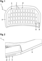
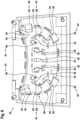
- Fig. 1 shows a top view of a PV panel 1 which may be produced in accordance with the method described herein.
- Fig. 2 shows a sectional view along the line A-A indicated in Fig. 1 .
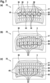
- the inner surface 35 at the core side moulding half 23 and the inner surface 37 at the cavity side moulding half 25 are formed such that, even in the closed state of the moulding device 27, there remains enough volume in between both inner surfaces 35, 37 such as to form a cavity 33.
- a thickness of this cavity 33 is larger than a thickness of the PV panel 3. Accordingly, even when the moulding device 27 is fully closed and the PV panel 3 is comprised in the cavity 33, there remains an empty volume in the cavity 33. In this empty volume, a polymer mass 29 may be generated, as describes in detail further below, such as to form the support structure 5 supporting the PV label 3.
- This continuous layer 39 is formed at least in a partial area of the PV label 3 in which the PV label 3 encloses the solar cell arrangement 17.
- the continuous layer 39 of polymer mass 29 extends along the entire rear surface 21 of the PV label 3 and even at least slightly beyond its lateral edges.
Landscapes
- Engineering & Computer Science (AREA)
- Manufacturing & Machinery (AREA)
- Mechanical Engineering (AREA)
- Injection Moulding Of Plastics Or The Like (AREA)
Priority Applications (3)
| Application Number | Priority Date | Filing Date | Title |
|---|---|---|---|
| EP22217402.1A EP4394896A1 (fr) | 2022-12-30 | 2022-12-30 | Procédé et dispositif de fabrication d'un panneau photovoltaïque comprenant un agencement de cellules solaires par moulage par injection-compression |
| EP23829075.3A EP4643396A1 (fr) | 2022-12-30 | 2023-12-18 | Procédé et dispositif de production de panneau photovoltaïque comprenant un agencement de cellules solaires utilisant un moulage par compression et par injection |
| PCT/EP2023/086412 WO2024141314A1 (fr) | 2022-12-30 | 2023-12-18 | Procédé et dispositif de production de panneau photovoltaïque comprenant un agencement de cellules solaires utilisant un moulage par compression et par injection |
Applications Claiming Priority (1)
| Application Number | Priority Date | Filing Date | Title |
|---|---|---|---|
| EP22217402.1A EP4394896A1 (fr) | 2022-12-30 | 2022-12-30 | Procédé et dispositif de fabrication d'un panneau photovoltaïque comprenant un agencement de cellules solaires par moulage par injection-compression |
Publications (1)
| Publication Number | Publication Date |
|---|---|
| EP4394896A1 true EP4394896A1 (fr) | 2024-07-03 |
Family
ID=84767138
Family Applications (2)
| Application Number | Title | Priority Date | Filing Date |
|---|---|---|---|
| EP22217402.1A Withdrawn EP4394896A1 (fr) | 2022-12-30 | 2022-12-30 | Procédé et dispositif de fabrication d'un panneau photovoltaïque comprenant un agencement de cellules solaires par moulage par injection-compression |
| EP23829075.3A Pending EP4643396A1 (fr) | 2022-12-30 | 2023-12-18 | Procédé et dispositif de production de panneau photovoltaïque comprenant un agencement de cellules solaires utilisant un moulage par compression et par injection |
Family Applications After (1)
| Application Number | Title | Priority Date | Filing Date |
|---|---|---|---|
| EP23829075.3A Pending EP4643396A1 (fr) | 2022-12-30 | 2023-12-18 | Procédé et dispositif de production de panneau photovoltaïque comprenant un agencement de cellules solaires utilisant un moulage par compression et par injection |
Country Status (2)
| Country | Link |
|---|---|
| EP (2) | EP4394896A1 (fr) |
| WO (1) | WO2024141314A1 (fr) |
Citations (6)
| Publication number | Priority date | Publication date | Assignee | Title |
|---|---|---|---|---|
| US20140251415A1 (en) * | 2013-03-08 | 2014-09-11 | Kabushiki Kaisha Toyota Jidoshokki | Solar panel and method for manufacturing the same |
| WO2019020718A1 (fr) | 2017-07-26 | 2019-01-31 | Sono Motors Gmbh | Élément de carrosserie et procédé de fabrication d'un élément de carrosserie |
| WO2020187792A1 (fr) | 2019-03-20 | 2020-09-24 | Sono Motors Gmbh | Procédé de fabrication de module photovoltaïque |
| WO2021260024A1 (fr) | 2020-06-24 | 2021-12-30 | Sono Motors Gmbh | Procédé de fabrication d'un module photovoltaïque incurvé comprenant un positionnement adapté de cellules photovoltaïques |
| WO2021260021A1 (fr) | 2020-06-24 | 2021-12-30 | Sono Motors Gmbh | Procédé de fabrication d'un module photovoltaïque comprenant la découpe au laser d'une étiquette photovoltaïque |
| WO2022122507A1 (fr) | 2020-12-11 | 2022-06-16 | Sono Motors Gmbh | Panneau de carrosserie de voiture comprenant un agencement de cellules solaires et son procédé de production |
Family Cites Families (2)
| Publication number | Priority date | Publication date | Assignee | Title |
|---|---|---|---|---|
| DE102022101935A1 (de) | 2022-01-27 | 2023-07-27 | Sono Motors Gmbh | Verfahren zur Herstellung eines photovoltaischen Panels, wie z.B. eines in die Fahrzeugkarosserie integrierten PV-Panels, unter Verwendung eines wärmehärtenden Polymers |
| DE102022108014A1 (de) | 2022-04-04 | 2023-10-05 | Sono Motors Gmbh | Verfahren zur Herstellung eines photovoltaischen Moduls durch In-Mould-Labeling mit spezifischem Temperaturmanagement |
-
2022
- 2022-12-30 EP EP22217402.1A patent/EP4394896A1/fr not_active Withdrawn
-
2023
- 2023-12-18 WO PCT/EP2023/086412 patent/WO2024141314A1/fr not_active Ceased
- 2023-12-18 EP EP23829075.3A patent/EP4643396A1/fr active Pending
Patent Citations (8)
| Publication number | Priority date | Publication date | Assignee | Title |
|---|---|---|---|---|
| US20140251415A1 (en) * | 2013-03-08 | 2014-09-11 | Kabushiki Kaisha Toyota Jidoshokki | Solar panel and method for manufacturing the same |
| WO2019020718A1 (fr) | 2017-07-26 | 2019-01-31 | Sono Motors Gmbh | Élément de carrosserie et procédé de fabrication d'un élément de carrosserie |
| WO2020187792A1 (fr) | 2019-03-20 | 2020-09-24 | Sono Motors Gmbh | Procédé de fabrication de module photovoltaïque |
| US20220278245A1 (en) * | 2019-03-20 | 2022-09-01 | Sono Motors Gmbh | Method For Manufacturing Of A Photovoltaic Module |
| WO2021260024A1 (fr) | 2020-06-24 | 2021-12-30 | Sono Motors Gmbh | Procédé de fabrication d'un module photovoltaïque incurvé comprenant un positionnement adapté de cellules photovoltaïques |
| WO2021260021A1 (fr) | 2020-06-24 | 2021-12-30 | Sono Motors Gmbh | Procédé de fabrication d'un module photovoltaïque comprenant la découpe au laser d'une étiquette photovoltaïque |
| GB2596522A (en) * | 2020-06-24 | 2022-01-05 | Sono Motors Gmbh | Method for fabricating a photovoltaic module including laser cutting of a photovoltaic label |
| WO2022122507A1 (fr) | 2020-12-11 | 2022-06-16 | Sono Motors Gmbh | Panneau de carrosserie de voiture comprenant un agencement de cellules solaires et son procédé de production |
Also Published As
| Publication number | Publication date |
|---|---|
| EP4643396A1 (fr) | 2025-11-05 |
| WO2024141314A1 (fr) | 2024-07-04 |
Similar Documents
| Publication | Publication Date | Title |
|---|---|---|
| EP4252348B1 (fr) | Panneau de carrosserie de voiture comprenant un agencement de cellules solaires et son procédé de production | |
| EP4470039A1 (fr) | Procédé de fabrication de panneau photovoltaïque tel qu'un panneau de carrosserie de véhicule intégré pv à l'aide d'un polymère thermodurcissable injecté avec moulage par injection de réaction | |
| EP3712964A1 (fr) | Procédé de fabrication d'un module photovoltaïque | |
| KR101249273B1 (ko) | 가요성 시트의 가장자리를 감싸는 개선된 방법 | |
| EP2775536B1 (fr) | Panneau solaire et son procédé de fabrication | |
| CN101933162B (zh) | 包括半导体层的太阳能电池层压板 | |
| JP5914803B2 (ja) | インモールド成形方法、及びインモールド成形装置 | |
| EP4505528A1 (fr) | Procédé de fabrication d'un module photovoltaïque faisant appel à un étiquetage en moule à gestion de température spécifique | |
| CN102470659A (zh) | 多层层压结构体及制造方法 | |
| IL278537B1 (en) | A flexible and lightweight photovoltaic module that includes a front layer made of polymer and a back layer made of composite material | |
| EP4280288A1 (fr) | Panneau sandwich photovoltaïque, en particulier panneau sandwich de revêtement de véhicule photovoltaïque et caisson de chargement à isolation thermique ainsi que véhicule comportant un tel panneau et procédé de fabrication | |
| EP4394896A1 (fr) | Procédé et dispositif de fabrication d'un panneau photovoltaïque comprenant un agencement de cellules solaires par moulage par injection-compression | |
| WO2024180145A1 (fr) | Procédé de production d'un panneau photovoltaïque tel qu'un panneau de carrosserie de véhicule intégré pv avec une structure de support arrière moulée et une structure de couvercle avant moulée directement revêtue | |
| EP4394897A1 (fr) | Procédé et dispositif de fabrication d'un panneau photovoltaïque doté d'une structure de support moulée par préfixation dans un dispositif de moulage | |
| WO2024133112A1 (fr) | Couvercle pour lit de charge ouvert de véhicule | |
| EP2294626B1 (fr) | Panneau photovoltaïque flexible et procédé de fabrication d'un tel panneau | |
| WO2024033403A1 (fr) | Procédé de fabrication d'un panneau photovoltaïque pour une carrosserie de véhicule avec un connecteur fixé par surmoulage | |
| EP4266379A1 (fr) | Panneau photovoltaïque, tel qu'un panneau de corps de véhicule intégré de panneau photovoltaïque et son procédé de fabrication l'utilisant procédure rouleau à rouleau | |
| DE102023105209A1 (de) | Verfahren zur Herstellung eines PV-Paneels, wie z.B. eines PV-integrierten Karosseriepaneels mit einer hinteren Trägerstruktur, die unter Verwendung einer Thermoformtechnik hergestellt wird | |
| EP4394895A1 (fr) | Panneau sandwich photovoltaïque, en particulier panneau sandwich de revêtement de véhicule photovoltaïque, à structure arrière à cadre en nid d'abeilles et procédé de fabrication | |
| WO2025031732A1 (fr) | Panneau photovoltaïque composite et procédé de fabrication | |
| JP2004198093A (ja) | 混成型太陽熱集熱パネルの製造装置 | |
| CN114586179A (zh) | 光伏收集器的制造方法及光伏收集器 |
Legal Events
| Date | Code | Title | Description |
|---|---|---|---|
| PUAI | Public reference made under article 153(3) epc to a published international application that has entered the european phase |
Free format text: ORIGINAL CODE: 0009012 |
|
| STAA | Information on the status of an ep patent application or granted ep patent |
Free format text: STATUS: THE APPLICATION HAS BEEN PUBLISHED |
|
| AK | Designated contracting states |
Kind code of ref document: A1 Designated state(s): AL AT BE BG CH CY CZ DE DK EE ES FI FR GB GR HR HU IE IS IT LI LT LU LV MC ME MK MT NL NO PL PT RO RS SE SI SK SM TR |
|
| STAA | Information on the status of an ep patent application or granted ep patent |
Free format text: STATUS: THE APPLICATION IS DEEMED TO BE WITHDRAWN |
|
| 18D | Application deemed to be withdrawn |
Effective date: 20250104 |