EP4394908A1 - Elektrodenplatte für eine wiederaufladbare batterie, herstellungsverfahren dafür und wiederaufladbare batterie damit - Google Patents
Elektrodenplatte für eine wiederaufladbare batterie, herstellungsverfahren dafür und wiederaufladbare batterie damit Download PDFInfo
- Publication number
- EP4394908A1 EP4394908A1 EP23198511.0A EP23198511A EP4394908A1 EP 4394908 A1 EP4394908 A1 EP 4394908A1 EP 23198511 A EP23198511 A EP 23198511A EP 4394908 A1 EP4394908 A1 EP 4394908A1
- Authority
- EP
- European Patent Office
- Prior art keywords
- active material
- material layer
- electrode plate
- current collector
- rechargeable battery
- Prior art date
- Legal status (The legal status is an assumption and is not a legal conclusion. Google has not performed a legal analysis and makes no representation as to the accuracy of the status listed.)
- Pending
Links
Images



Classifications
-
- H—ELECTRICITY
- H01—ELECTRIC ELEMENTS
- H01M—PROCESSES OR MEANS, e.g. BATTERIES, FOR THE DIRECT CONVERSION OF CHEMICAL ENERGY INTO ELECTRICAL ENERGY
- H01M4/00—Electrodes
- H01M4/02—Electrodes composed of, or comprising, active material
-
- H—ELECTRICITY
- H01—ELECTRIC ELEMENTS
- H01M—PROCESSES OR MEANS, e.g. BATTERIES, FOR THE DIRECT CONVERSION OF CHEMICAL ENERGY INTO ELECTRICAL ENERGY
- H01M4/00—Electrodes
- H01M4/02—Electrodes composed of, or comprising, active material
- H01M4/13—Electrodes for accumulators with non-aqueous electrolyte, e.g. for lithium-accumulators; Processes of manufacture thereof
-
- H—ELECTRICITY
- H01—ELECTRIC ELEMENTS
- H01M—PROCESSES OR MEANS, e.g. BATTERIES, FOR THE DIRECT CONVERSION OF CHEMICAL ENERGY INTO ELECTRICAL ENERGY
- H01M10/00—Secondary cells; Manufacture thereof
- H01M10/04—Construction or manufacture in general
-
- H—ELECTRICITY
- H01—ELECTRIC ELEMENTS
- H01M—PROCESSES OR MEANS, e.g. BATTERIES, FOR THE DIRECT CONVERSION OF CHEMICAL ENERGY INTO ELECTRICAL ENERGY
- H01M10/00—Secondary cells; Manufacture thereof
- H01M10/05—Accumulators with non-aqueous electrolyte
- H01M10/052—Li-accumulators
-
- H—ELECTRICITY
- H01—ELECTRIC ELEMENTS
- H01M—PROCESSES OR MEANS, e.g. BATTERIES, FOR THE DIRECT CONVERSION OF CHEMICAL ENERGY INTO ELECTRICAL ENERGY
- H01M10/00—Secondary cells; Manufacture thereof
- H01M10/05—Accumulators with non-aqueous electrolyte
- H01M10/052—Li-accumulators
- H01M10/0525—Rocking-chair batteries, i.e. batteries with lithium insertion or intercalation in both electrodes; Lithium-ion batteries
-
- H—ELECTRICITY
- H01—ELECTRIC ELEMENTS
- H01M—PROCESSES OR MEANS, e.g. BATTERIES, FOR THE DIRECT CONVERSION OF CHEMICAL ENERGY INTO ELECTRICAL ENERGY
- H01M10/00—Secondary cells; Manufacture thereof
- H01M10/42—Methods or arrangements for servicing or maintenance of secondary cells or secondary half-cells
- H01M10/4235—Safety or regulating additives or arrangements in electrodes, separators or electrolyte
-
- H—ELECTRICITY
- H01—ELECTRIC ELEMENTS
- H01M—PROCESSES OR MEANS, e.g. BATTERIES, FOR THE DIRECT CONVERSION OF CHEMICAL ENERGY INTO ELECTRICAL ENERGY
- H01M4/00—Electrodes
- H01M4/02—Electrodes composed of, or comprising, active material
- H01M4/04—Processes of manufacture in general
- H01M4/0402—Methods of deposition of the material
- H01M4/0404—Methods of deposition of the material by coating on electrode collectors
-
- H—ELECTRICITY
- H01—ELECTRIC ELEMENTS
- H01M—PROCESSES OR MEANS, e.g. BATTERIES, FOR THE DIRECT CONVERSION OF CHEMICAL ENERGY INTO ELECTRICAL ENERGY
- H01M4/00—Electrodes
- H01M4/02—Electrodes composed of, or comprising, active material
- H01M4/04—Processes of manufacture in general
- H01M4/0471—Processes of manufacture in general involving thermal treatment, e.g. firing, sintering, backing particulate active material, thermal decomposition, pyrolysis
-
- H—ELECTRICITY
- H01—ELECTRIC ELEMENTS
- H01M—PROCESSES OR MEANS, e.g. BATTERIES, FOR THE DIRECT CONVERSION OF CHEMICAL ENERGY INTO ELECTRICAL ENERGY
- H01M4/00—Electrodes
- H01M4/02—Electrodes composed of, or comprising, active material
- H01M4/13—Electrodes for accumulators with non-aqueous electrolyte, e.g. for lithium-accumulators; Processes of manufacture thereof
- H01M4/139—Processes of manufacture
-
- H—ELECTRICITY
- H01—ELECTRIC ELEMENTS
- H01M—PROCESSES OR MEANS, e.g. BATTERIES, FOR THE DIRECT CONVERSION OF CHEMICAL ENERGY INTO ELECTRICAL ENERGY
- H01M4/00—Electrodes
- H01M4/02—Electrodes composed of, or comprising, active material
- H01M4/36—Selection of substances as active materials, active masses, active liquids
- H01M4/362—Composites
- H01M4/366—Composites as layered products
-
- H—ELECTRICITY
- H01—ELECTRIC ELEMENTS
- H01M—PROCESSES OR MEANS, e.g. BATTERIES, FOR THE DIRECT CONVERSION OF CHEMICAL ENERGY INTO ELECTRICAL ENERGY
- H01M4/00—Electrodes
- H01M4/02—Electrodes composed of, or comprising, active material
- H01M4/36—Selection of substances as active materials, active masses, active liquids
- H01M4/38—Selection of substances as active materials, active masses, active liquids of elements or alloys
- H01M4/386—Silicon or alloys based on silicon
-
- H—ELECTRICITY
- H01—ELECTRIC ELEMENTS
- H01M—PROCESSES OR MEANS, e.g. BATTERIES, FOR THE DIRECT CONVERSION OF CHEMICAL ENERGY INTO ELECTRICAL ENERGY
- H01M4/00—Electrodes
- H01M4/02—Electrodes composed of, or comprising, active material
- H01M4/36—Selection of substances as active materials, active masses, active liquids
- H01M4/58—Selection of substances as active materials, active masses, active liquids of inorganic compounds other than oxides or hydroxides, e.g. sulfides, selenides, tellurides, halogenides or LiCoFy; of polyanionic structures, e.g. phosphates, silicates or borates
- H01M4/583—Carbonaceous material, e.g. graphite-intercalation compounds or CFx
- H01M4/587—Carbonaceous material, e.g. graphite-intercalation compounds or CFx for inserting or intercalating light metals
-
- H—ELECTRICITY
- H01—ELECTRIC ELEMENTS
- H01M—PROCESSES OR MEANS, e.g. BATTERIES, FOR THE DIRECT CONVERSION OF CHEMICAL ENERGY INTO ELECTRICAL ENERGY
- H01M4/00—Electrodes
- H01M4/02—Electrodes composed of, or comprising, active material
- H01M4/64—Carriers or collectors
- H01M4/66—Selection of materials
- H01M4/661—Metal or alloys, e.g. alloy coatings
-
- H—ELECTRICITY
- H01—ELECTRIC ELEMENTS
- H01M—PROCESSES OR MEANS, e.g. BATTERIES, FOR THE DIRECT CONVERSION OF CHEMICAL ENERGY INTO ELECTRICAL ENERGY
- H01M4/00—Electrodes
- H01M4/02—Electrodes composed of, or comprising, active material
- H01M2004/021—Physical characteristics, e.g. porosity, surface area
-
- Y—GENERAL TAGGING OF NEW TECHNOLOGICAL DEVELOPMENTS; GENERAL TAGGING OF CROSS-SECTIONAL TECHNOLOGIES SPANNING OVER SEVERAL SECTIONS OF THE IPC; TECHNICAL SUBJECTS COVERED BY FORMER USPC CROSS-REFERENCE ART COLLECTIONS [XRACs] AND DIGESTS
- Y02—TECHNOLOGIES OR APPLICATIONS FOR MITIGATION OR ADAPTATION AGAINST CLIMATE CHANGE
- Y02E—REDUCTION OF GREENHOUSE GAS [GHG] EMISSIONS, RELATED TO ENERGY GENERATION, TRANSMISSION OR DISTRIBUTION
- Y02E60/00—Enabling technologies; Technologies with a potential or indirect contribution to GHG emissions mitigation
- Y02E60/10—Energy storage using batteries
Definitions
- the present disclosure relates to an electrode plate for a rechargeable battery, a manufacturing method thereof, and a rechargeable battery using the same.
- a rechargeable battery is a battery that repeatedly performs charging and discharging, unlike a primary battery.
- a small-capacity rechargeable battery is used in a portable small electronic device such as a mobile phone, a laptop computer, or a camcorder.
- a large-capacity and high-density rechargeable battery is used as a power source for driving a motor of a hybrid vehicle or an electric vehicle or an energy storage device of the hybrid vehicle or the electric vehicle.
- the rechargeable battery includes an electrode assembly for charging and discharging a current, a case or a pouch for accommodating the electrode assembly and an electrolyte, and an electrode terminal connected to the electrode assembly to draw the electrode assembly out to the outside of the case or the pouch.
- the electrode assembly may be formed of a jelly roll type formed by winding an electrode plate and a separator or a stack type formed by stacking an electrode plate and a separator.
- the electrode plate in order to improve a characteristic of the electrode plate, different composites may be used in a thickness direction.
- the electrode plate has a characteristic effect in the thickness direction as well as a characteristic effect in a width direction. Therefore, it is necessary to appropriately control the characteristic effects of the electrode plate in the thickness and width directions.
- An embodiment of the present disclosure is to provide an electrode plate for a rechargeable battery that improves an impregnation characteristic of an electrolyte by inducing bending in a width direction of the electrode plate to improve rate capability, and a manufacturing method thereof.
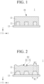
- FIG. 1 is a cross-sectional view of an electrode plate for a rechargeable battery according to an embodiment of the present disclosure and is a state diagram in which a first active material layer and a second active material layer are coated on an electrode current collector
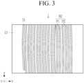
- FIG. 2 is a cross-sectional view of the electrode plate for the rechargeable battery of FIG. 1 and is a cross-sectional view illustrating a state in which the first active material layer and the second active material layer coated on the electrode current collector are dried
- FIG. 3 is a plane view of the electrode plate for the rechargeable battery of FIG. 2 .
- the electrode plate 1 for the rechargeable battery includes the electrode current collector 13, the first active material layer 11, and the second active material layer 12.
- the electrode current collector 13 is formed of a thin metal plate.
- a material constituting the electrode current collector 13 may be any material that does not react with lithium, does not form an alloy or a compound with lithium, and has conductivity.
- the material may be a metal or an alloy.
- the metal may include indium (In), copper (Cu), magnesium (Mg), stainless steel, titanium (Ti), iron (Fe), cobalt (Co), nickel (Ni), zinc (Zn), aluminum (Al), germanium (Ge), lithium (Li), or an alloy thereof.
- the electrode current collector 13 may have a form selected from a sheet, a foil, a film, a plate, a porous material, a mesoporous material, a through hole-containing material, a polygonal ring, a mesh, a foam, and a nonwoven fabric, but the present disclosure is not necessarily limited to the form, and any form used in the art is possible.
- the first active material layer 11 is formed in a pattern on the electrode current collector 13.
- the pattern may be such that the first active material layer 11 covers only parts of the electrode current collector 13, i.e. there are uncoated areas between coated areas.
- the first active material layer 11 may be formed in a plurality of rows spaced apart in a width direction (an X-axis direction) at at least one surface of the electrode current collector 13, and may be continuously formed in a longitudinal direction (a Y-axis direction) crossing the width direction.
- the first active material layer 11 After the first active material layer 11 is dried, the first active material layer 11 has a trapezoidal cross-sectional structure in the electrode plate 1 for the rechargeable battery. That is, the first active material layer 11 is formed to have a first width W1 at a side of the electrode current collector 13, and is formed to have a second width W2 less than the first width W1 at a side of a surface of the second active material layer 12.
- the first active material layer 11 may include a negative electrode active material, a binder, and optionally a conductive material.
- a carbon-based active material or a silicon-based active material may be used as the negative electrode active material.
- the carbon-based active material may be a carbon-containing active material generally used in a negative electrode, and may include crystalline carbon, amorphous carbon, or a combination thereof.
- An example of the crystalline carbon may include natural graphite or artificial graphite that has no-shape, or sheet, flake, spherical, or fiber shape, and an example of the amorphous carbon may include a soft carbon, a hard carbon, mesophase pitch carbide, fired coke, or the like.
- the silicon-based active material may include silicon, a silicon-carbon composite, SiO x (0 ⁇ x ⁇ 2), an Si-Q alloy (where Q is an element selected from the group consisting of an alkali metal, an alkaline-earth metal, a group 13 element, a group 14 element, a group 15 element, a group 16 element, a transition metal, a rare earth element, and a combination thereof, and is not Si), or a combination thereof, and may be used by mixing at least one of these materials with SiO 2 .
- Q is an element selected from the group consisting of an alkali metal, an alkaline-earth metal, a group 13 element, a group 14 element, a group 15 element, a group 16 element, a transition metal, a rare earth element, and a combination thereof, and is not Si
- Q is an element selected from the group consisting of an alkali metal, an alkaline-earth metal, a group 13 element, a group 14 element, a group 15 element, a
- the element Q may be an element selected from the group consisting of Mg, Ca, Sr, Ba, Ra, Sc, Y, Ti, Zr, Hf, Rf, V, Nb, Ta, Db, Cr, Mo, W, Sg, Tc, Re, Bh, Fe, Pb, Ru, Os, Hs, Rh, Ir, Pd, Pt, Cu, Ag, Au, Zn, Cd, B, Al, Ga, Sn, In, TI, Ge, P, As, Sb, Bi, S, Se, Te, Po, and a combination thereof.
- the silicon-based active material may include a silicon-carbon composite including a silicon particle and a first carbon-based material.
- the first carbon-based material may be crystalline carbon, amorphous carbon, or a combination thereof.
- a content of the silicon particle may be 30 wt% to 70 wt%.
- the content of the silicon particle may be 40 wt% to 50 wt%.
- a content of the first carbon-based material may be 70 wt% to 30 wt%.
- the content of the first carbon-based material may be 50 wt% to 60 wt%.
- the binder serves to well attach negative electrode active material particles to each other and to well attach the negative electrode active material to the current collector.
- a non-aqueous binder, an aqueous binder, or a combination thereof may be used as the binder.
- the non-aqueous binder may include an ethylene propylene copolymer, polyacrylonitrile, polystyrene, polyvinylchloride, carboxylated polyvinylchloride, polyvinylfluoride, polyurethane, polytetrafluoroethylene, polyvinylidene fluoride, polyethylene, polypropylene, polyamideimide, polyimide, or a combination thereof.
- the aqueous binder may include a styrene-butadiene rubber, an acrylated styrene-butadiene rubber (ABR), an acrylonitrile-butadiene rubber, an acrylic rubber, a butyl rubber, a fluorine rubber, an ethylene oxide-containing polymer, polyvinyl pyrrolidone, polyepichlorohydrin, polyphosphazene, an ethylene propylene diene copolymer, polyvinylpyridine, chlorosulfonated polyethylene, latex, a polyester resin, an acrylic resin, a phenolic resin, an epoxy resin, polyvinyl alcohol, or a combinations thereof.
- ABR acrylated styrene-butadiene rubber
- ABR acrylated styrene-butadiene rubber
- an acrylonitrile-butadiene rubber an acrylic rubber, a butyl rubber, a fluorine rubber, an ethylene oxide-containing poly
- the conductive material may be used to impart conductivity to the electrode, and the conductive material that does not cause chemical change and is an electronic conductive material may be used in the battery.
- An example of the conductive material may be a conductive material including a carbon-based material such as natural graphite, artificial graphite, carbon black, acetylene black, ketjen black, a carbon fiber, or the like, a metal-based material such as a metal powder, a metal fiber, or the like of copper, nickel, aluminum, silver, or the like, a conductive polymer such as a polyphenylene derivative or the like, or a mixture thereof.
- the second active material layer 12 When the second active material layer 12 is dried, the second active material layer 12 has a second roughness R2 of FIGS. 2 and 3 greater than a first roughness R1 of FIG. 1 of a surface of the second active material layer prior to drying (i.e. when the second active material layer 12 is coated).
- a slurry of the first active material is first applied to a surface of the electrode current collector in a pattern.
- the first active material layer 11 is formed.
- the first active material layer 11 is then overlaid with a slurry of the second active material.
- the surface of the still paste-like layer of the second active material has a roughness R1.
- the second active material layer 12 is formed by drying the slurry and has a roughness R2.
- the roughness R2 of the second active material layer 12 is increased compared to the roughness R1 of the coated slurry.
- the second active material layer 12 includes the second active material with 95.40 wt% to 98.48 wt%, the conductive material with 0.027 wt% to 1.01 wt%, the thickener with 0.90 wt% to 1.01 wt%, and the binder with 0.40 wt% to 1.70 wt%, wherein the ingredients sum up to 100 wt%. Deterioration in processability of the electrode plate 1 and a cell characteristic may occur if the respective ratio is out of range.
- the second roughness R2 of the surface of the second active material layer 12 of the embodiment increases the contact angle. That is, the second roughness R2 increases the contact angle of the surface of the second active material layer 12 with respect to an electrolyte to improve an impregnation characteristic of the electrolyte with respect to the second active material layer 12 in a width direction (an X-axis direction) of the electrode plate 1 for the rechargeable battery.
- FIG. 4 is a graph comparing impregnation rates of electrolytes for the comparative example and the embodiment.
- the surface of the active material layer of the comparative example has a contact angle of 97° and an electrolyte impregnation rate with 12.1 %.
- the surface of the second active material layer 12 of the embodiment has a contact angle of 105°and an electrolyte impregnation rate of 14.7 %.
- the electrode plate 1 for the rechargeable battery of the embodiment Due to a difference in the electrolyte impregnation rate, the electrode plate 1 for the rechargeable battery of the embodiment has a higher rate capability than the comparative example in the width direction (the X-axis direction).
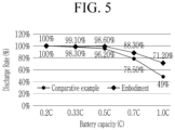
- FIG. 5 is a graph comparing a relationship between a battery capacity and a discharge rate for the comparative example and the embodiment.
- the surface of the active material layer of the comparative example has the discharge rate of 49 % due to the electrolyte impregnation rate of 12.1 % at 0.2 coulomb (C) discharge to 1.0 coulomb (C) discharge of the battery capacity.
- the surface of the second active material layer 12 of the embodiment has the discharge rate of 71.2 % due to the electrolyte impregnation rate of 14.7 % at 0.2 coulomb (C) discharge to 1.0 coulomb (C) discharge of the battery capacity. That is, the example has improved rate capability since a drop in the discharge rate of the example is less than that of the comparative example.
- FIG. 6 is a flowchart of a manufacturing method of the electrode plate for the rechargeable battery according to an embodiment of the present disclosure.
- the manufacturing method of the electrode plate for the rechargeable battery of the embodiment includes a first step ST1, a second step ST2, and a third step ST3.
- a thin electrode current collector 13 is provided, respectively prepared.
- the electrode current collector 13 may be formed of a copper or aluminum thin plate depending on whether it is a negative electrode current collector or a positive electrode current collector.
- the first active material layer 11 is formed by coating a first active material slurry on the electrode current collector 13 in a pattern.
- the second step ST2 further includes a step of drying the first active material layer 11. In the drying step, the first active material layer 11 coated in the pattern is dried.
- the first active material layer 11 may be formed at one surface of the electrode current collector 13 (see a single-sided second electrode plate (or a single-surface second electrode plate) 213 of FIG. 8 ), but may be sequentially formed at both surfaces of the electrode current collector 13 (see first electrode plates 111 and 211 and second electrode plates 112 and 212 of FIGS. 7 and 8 ).
- the second active material layer 12 is formed by coating a second active material slurry on the first active material layer 11 and the electrode current collector 13.
- the second active material slurry is coated also on a surface of the electrode current collector 13 at which the first active material layer 11 is not formed.
- the first active material layer 11 and the second active material layer 12 are alternately formed in the width direction (the X-axis direction) at a portion adjacent to the surface of the electrode current collector 13.
- a portion where the first active material layer 11 is provided forms a two-layer structure of the first and second active material layers 11 and 12.
- a portion where the first active material layer 11 is not provided forms a single layer structure of the second active material layer 12.
- the third step ST3 further includes a step of drying the second active material layer 12.
- the coated second active material layer 12 is dried.
- the second and third steps ST2 and ST3 in which the first active material slurry is coated and dried and then the second active material is coated and dried may be repeatedly performed.
- the first and second active material slurries may be coated with a difference in coating time to be coated at the same time, and then may be dried at the same time.
- FIG. 7 is a perspective view of the rechargeable battery according to a first embodiment of the present disclosure.
- the rechargeable battery 100 of the first embodiment includes an electrode assembly 10 for charging and discharging an electric current, and a pouch 20 accommodating the electrode assembly 10 and an electrolyte.
- the pouch 20 forms a sealing portion by thermally bonding outer edges of a first exterior portion 201 and a second exterior portion 202.
- the first and second exterior portions 201 and 202 are integrally connected by a rear connection portion 203.
- the first and second exterior portions may be separately formed without the rear connection portion to be thermally bonded at outer edges of the first exterior portion and the second exterior portion.
- the electrode assembly 10 is formed in a form of a jelly roll by disposing the first electrode plate (referred to as a positive electrode plate for convenience) 111 and the second electrode plate (referred to as a negative electrode plate for convenience) 112 with a separator 113 interposed therebetween to wind the first electrode plate, the second electrode plate, and the separator.
- first electrode plate referred to as a positive electrode plate for convenience
- second electrode plate referred to as a negative electrode plate for convenience
- the electrode assembly 10 is formed flat by pressing a side surface of the wound cylindrical shape.
- the electrode assembly 10 is connected to the positive electrode plate 111 and the negative electrode plate 112 to be drawn out of the pouch 20 through a first tab 14 and a second tab 15 provided at one side of a winding end surface.
- the first tab 14 and the second tab 15 are disposed at the sealing portion with insulating tapes 16 and 17 interposed therebetween.
- the positive electrode plate 111 includes a coated portion in which a positive electrode active material is applied to an electrode current collector of a thin metal plate and an uncoated portion set as an electrode current collector exposed by not applying the positive electrode active material.
- the first tab 14 connected to the electrode current collector and the uncoated portion of the positive electrode plate 111 may be formed of aluminum (Al).
- the negative electrode plate 112 includes a coated portion in which a negative electrode active material different from the active material of the positive electrode plate 111 is applied to an electrode current collector of a thin metal plate and an uncoated portion set as an electrode current collector exposed by not applying the negative electrode active material.
- the electrode current collector and the uncoated portion of the negative electrode plate 112 may be formed of copper (Cu), and the second tab 15 connected to the uncoated portion may be formed of nickel (Ni).
- the second active material layer 12 forms the second roughness R2 greater than the first roughness R1 of a surface of the second active material layer formed when the second active material layer 12 is coated.
- the first active material layer 11 has a trapezoidal cross-sectional structure.
- the first active material layer 11 has the first width W1 at a side of the electrode current collector 13 and the second width W2 less than the first width W1 at a side of a surface of the second active material layer 12.
- the second active material layer 12 has a surface contact angle of 100° to 110° at a surface of the second active material layer 12.
Landscapes
- Chemical & Material Sciences (AREA)
- Chemical Kinetics & Catalysis (AREA)
- Electrochemistry (AREA)
- General Chemical & Material Sciences (AREA)
- Engineering & Computer Science (AREA)
- Manufacturing & Machinery (AREA)
- Materials Engineering (AREA)
- Composite Materials (AREA)
- Inorganic Chemistry (AREA)
- Battery Electrode And Active Subsutance (AREA)
Applications Claiming Priority (1)
| Application Number | Priority Date | Filing Date | Title |
|---|---|---|---|
| KR1020220184839A KR20240102624A (ko) | 2022-12-26 | 2022-12-26 | 이차전지용 전극판, 이의 제조방법, 및 이를 이용한 이차전지 |
Publications (1)
| Publication Number | Publication Date |
|---|---|
| EP4394908A1 true EP4394908A1 (de) | 2024-07-03 |
Family
ID=88098417
Family Applications (1)
| Application Number | Title | Priority Date | Filing Date |
|---|---|---|---|
| EP23198511.0A Pending EP4394908A1 (de) | 2022-12-26 | 2023-09-20 | Elektrodenplatte für eine wiederaufladbare batterie, herstellungsverfahren dafür und wiederaufladbare batterie damit |
Country Status (4)
| Country | Link |
|---|---|
| US (1) | US20240213454A1 (de) |
| EP (1) | EP4394908A1 (de) |
| KR (1) | KR20240102624A (de) |
| CN (1) | CN118263387A (de) |
Citations (4)
| Publication number | Priority date | Publication date | Assignee | Title |
|---|---|---|---|---|
| JPH09115519A (ja) * | 1995-10-16 | 1997-05-02 | Toshiba Battery Co Ltd | アルカリ二次電池 |
| JP2014120404A (ja) * | 2012-12-18 | 2014-06-30 | Mitsubishi Motors Corp | 二次電池 |
| CN109267135A (zh) * | 2018-11-29 | 2019-01-25 | 上海交通大学 | 一种三维网络互穿有机/无机疏水涂层及其制备方法 |
| CN112713259A (zh) * | 2020-12-30 | 2021-04-27 | 珠海冠宇电池股份有限公司 | 一种极片和锂离子电池 |
-
2022
- 2022-12-26 KR KR1020220184839A patent/KR20240102624A/ko active Pending
-
2023
- 2023-09-14 CN CN202311188239.1A patent/CN118263387A/zh active Pending
- 2023-09-18 US US18/469,416 patent/US20240213454A1/en active Pending
- 2023-09-20 EP EP23198511.0A patent/EP4394908A1/de active Pending
Patent Citations (4)
| Publication number | Priority date | Publication date | Assignee | Title |
|---|---|---|---|---|
| JPH09115519A (ja) * | 1995-10-16 | 1997-05-02 | Toshiba Battery Co Ltd | アルカリ二次電池 |
| JP2014120404A (ja) * | 2012-12-18 | 2014-06-30 | Mitsubishi Motors Corp | 二次電池 |
| CN109267135A (zh) * | 2018-11-29 | 2019-01-25 | 上海交通大学 | 一种三维网络互穿有机/无机疏水涂层及其制备方法 |
| CN112713259A (zh) * | 2020-12-30 | 2021-04-27 | 珠海冠宇电池股份有限公司 | 一种极片和锂离子电池 |
Also Published As
| Publication number | Publication date |
|---|---|
| US20240213454A1 (en) | 2024-06-27 |
| KR20240102624A (ko) | 2024-07-03 |
| CN118263387A (zh) | 2024-06-28 |
Similar Documents
| Publication | Publication Date | Title |
|---|---|---|
| CN104067417B (zh) | 二次电池用电极、包含其的二次电池和线缆型二次电池 | |
| US8076027B2 (en) | Negative electrode for lithium secondary battery, lithium secondary battery using same, and methods for manufacturing those | |
| KR101265193B1 (ko) | 이차 전지 및 그 제조 방법 | |
| JP7282925B2 (ja) | リチウム二次電池用正極、その製造方法、及びそれを含むリチウム二次電池 | |
| CN104067418B (zh) | 二次电池用电极、包含其的二次电池和线缆型二次电池 | |
| CN204464387U (zh) | 线缆型二次电池 | |
| JP2020077611A (ja) | リチウム二次電池用正極活物質およびこれを含むリチウム二次電池 | |
| CN113193225A (zh) | 锂二次电池 | |
| EP2770558A2 (de) | Batterie mit einer elektrodenstruktur mit langen metallischen fasern und herstellungsverfahren dafür | |
| CN114846656A (zh) | 电极和电极组件 | |
| CN116487586B (zh) | 包括具有竹型纤维的聚合物粘合剂网络的电极 | |
| CN108012572A (zh) | 电极组件及其制造方法 | |
| JP6926910B2 (ja) | 二次電池 | |
| US20240213454A1 (en) | Electrode plate for rechargeable battery, manufacturing method thereof, and rechargeable battery using the same | |
| US20220246987A1 (en) | Ternary salts electrolyte for a phospho-olivine positive electrode | |
| US20260106139A1 (en) | Electrode structure, method of manufacturing the electrode structure, and secondary battery including the electrode structure | |
| US20260106227A1 (en) | Electrode, secondary battery and method for manufacturing electrode | |
| CN115084429B (zh) | 一种正极片及锂离子电池 | |
| JP7860447B2 (ja) | 非水電解質二次電池 | |
| JP7809171B2 (ja) | 電極アセンブリおよびこれを含む二次電池 | |
| EP4478472A1 (de) | Elektrodenanordnung mit positivelektrode mit isolierender deckschicht und verfahren zur herstellung davon | |
| EP4550516A2 (de) | Elektrode für eine wiederaufladbare batterie, elektrodenanordnung und wiederaufladbare batterie damit | |
| US20250233152A1 (en) | Electrode assembly and rechargeable battery including the same | |
| JP2000208135A (ja) | 非水電解質電池用正極およびその製造方法 | |
| KR20240159459A (ko) | 절연 코팅층이 구비된 양극을 포함하는 전극조립체 및 이의 제조방법 |
Legal Events
| Date | Code | Title | Description |
|---|---|---|---|
| PUAI | Public reference made under article 153(3) epc to a published international application that has entered the european phase |
Free format text: ORIGINAL CODE: 0009012 |
|
| STAA | Information on the status of an ep patent application or granted ep patent |
Free format text: STATUS: REQUEST FOR EXAMINATION WAS MADE |
|
| 17P | Request for examination filed |
Effective date: 20230920 |
|
| AK | Designated contracting states |
Kind code of ref document: A1 Designated state(s): AL AT BE BG CH CY CZ DE DK EE ES FI FR GB GR HR HU IE IS IT LI LT LU LV MC ME MK MT NL NO PL PT RO RS SE SI SK SM TR |