EP4394958A1 - Elektrochemische zelle, elektrochemische zellenvorrichtung, modul und modulspeichervorrichtung - Google Patents
Elektrochemische zelle, elektrochemische zellenvorrichtung, modul und modulspeichervorrichtung Download PDFInfo
- Publication number
- EP4394958A1 EP4394958A1 EP22876360.3A EP22876360A EP4394958A1 EP 4394958 A1 EP4394958 A1 EP 4394958A1 EP 22876360 A EP22876360 A EP 22876360A EP 4394958 A1 EP4394958 A1 EP 4394958A1
- Authority
- EP
- European Patent Office
- Prior art keywords
- electrochemical cell
- electrode layer
- solid electrolyte
- module
- electrolyte layer
- Prior art date
- Legal status (The legal status is an assumption and is not a legal conclusion. Google has not performed a legal analysis and makes no representation as to the accuracy of the status listed.)
- Pending
Links
Images




Classifications
-
- H—ELECTRICITY
- H01—ELECTRIC ELEMENTS
- H01M—PROCESSES OR MEANS, e.g. BATTERIES, FOR THE DIRECT CONVERSION OF CHEMICAL ENERGY INTO ELECTRICAL ENERGY
- H01M8/00—Fuel cells; Manufacture thereof
- H01M8/10—Fuel cells with solid electrolytes
- H01M8/12—Fuel cells with solid electrolytes operating at high temperature, e.g. with stabilised ZrO2 electrolyte
- H01M8/1213—Fuel cells with solid electrolytes operating at high temperature, e.g. with stabilised ZrO2 electrolyte characterised by the electrode/electrolyte combination or the supporting material
-
- H—ELECTRICITY
- H01—ELECTRIC ELEMENTS
- H01M—PROCESSES OR MEANS, e.g. BATTERIES, FOR THE DIRECT CONVERSION OF CHEMICAL ENERGY INTO ELECTRICAL ENERGY
- H01M4/00—Electrodes
- H01M4/86—Inert electrodes with catalytic activity, e.g. for fuel cells
- H01M4/8605—Porous electrodes
- H01M4/861—Porous electrodes with a gradient in the porosity
-
- H—ELECTRICITY
- H01—ELECTRIC ELEMENTS
- H01M—PROCESSES OR MEANS, e.g. BATTERIES, FOR THE DIRECT CONVERSION OF CHEMICAL ENERGY INTO ELECTRICAL ENERGY
- H01M4/00—Electrodes
- H01M4/86—Inert electrodes with catalytic activity, e.g. for fuel cells
- H01M4/8636—Inert electrodes with catalytic activity, e.g. for fuel cells with a gradient in another property than porosity
- H01M4/8642—Gradient in composition
-
- H—ELECTRICITY
- H01—ELECTRIC ELEMENTS
- H01M—PROCESSES OR MEANS, e.g. BATTERIES, FOR THE DIRECT CONVERSION OF CHEMICAL ENERGY INTO ELECTRICAL ENERGY
- H01M4/00—Electrodes
- H01M4/86—Inert electrodes with catalytic activity, e.g. for fuel cells
- H01M4/8647—Inert electrodes with catalytic activity, e.g. for fuel cells consisting of more than one material, e.g. consisting of composites
- H01M4/8652—Inert electrodes with catalytic activity, e.g. for fuel cells consisting of more than one material, e.g. consisting of composites as mixture
-
- H—ELECTRICITY
- H01—ELECTRIC ELEMENTS
- H01M—PROCESSES OR MEANS, e.g. BATTERIES, FOR THE DIRECT CONVERSION OF CHEMICAL ENERGY INTO ELECTRICAL ENERGY
- H01M4/00—Electrodes
- H01M4/86—Inert electrodes with catalytic activity, e.g. for fuel cells
- H01M4/8647—Inert electrodes with catalytic activity, e.g. for fuel cells consisting of more than one material, e.g. consisting of composites
- H01M4/8657—Inert electrodes with catalytic activity, e.g. for fuel cells consisting of more than one material, e.g. consisting of composites layered
-
- H—ELECTRICITY
- H01—ELECTRIC ELEMENTS
- H01M—PROCESSES OR MEANS, e.g. BATTERIES, FOR THE DIRECT CONVERSION OF CHEMICAL ENERGY INTO ELECTRICAL ENERGY
- H01M4/00—Electrodes
- H01M4/86—Inert electrodes with catalytic activity, e.g. for fuel cells
- H01M4/90—Selection of catalytic material
- H01M4/9016—Oxides, hydroxides or oxygenated metallic salts
- H01M4/9025—Oxides specially used in fuel cell operating at high temperature, e.g. SOFC
-
- H—ELECTRICITY
- H01—ELECTRIC ELEMENTS
- H01M—PROCESSES OR MEANS, e.g. BATTERIES, FOR THE DIRECT CONVERSION OF CHEMICAL ENERGY INTO ELECTRICAL ENERGY
- H01M4/00—Electrodes
- H01M4/86—Inert electrodes with catalytic activity, e.g. for fuel cells
- H01M4/90—Selection of catalytic material
- H01M4/9016—Oxides, hydroxides or oxygenated metallic salts
- H01M4/9025—Oxides specially used in fuel cell operating at high temperature, e.g. SOFC
- H01M4/9033—Complex oxides, optionally doped, of the type M1MeO3, M1 being an alkaline earth metal or a rare earth, Me being a metal, e.g. perovskites
-
- H—ELECTRICITY
- H01—ELECTRIC ELEMENTS
- H01M—PROCESSES OR MEANS, e.g. BATTERIES, FOR THE DIRECT CONVERSION OF CHEMICAL ENERGY INTO ELECTRICAL ENERGY
- H01M8/00—Fuel cells; Manufacture thereof
- H01M8/002—Shape, form of a fuel cell
- H01M8/004—Cylindrical, tubular or wound
-
- H—ELECTRICITY
- H01—ELECTRIC ELEMENTS
- H01M—PROCESSES OR MEANS, e.g. BATTERIES, FOR THE DIRECT CONVERSION OF CHEMICAL ENERGY INTO ELECTRICAL ENERGY
- H01M8/00—Fuel cells; Manufacture thereof
- H01M8/10—Fuel cells with solid electrolytes
- H01M8/12—Fuel cells with solid electrolytes operating at high temperature, e.g. with stabilised ZrO2 electrolyte
-
- H—ELECTRICITY
- H01—ELECTRIC ELEMENTS
- H01M—PROCESSES OR MEANS, e.g. BATTERIES, FOR THE DIRECT CONVERSION OF CHEMICAL ENERGY INTO ELECTRICAL ENERGY
- H01M8/00—Fuel cells; Manufacture thereof
- H01M8/10—Fuel cells with solid electrolytes
- H01M8/12—Fuel cells with solid electrolytes operating at high temperature, e.g. with stabilised ZrO2 electrolyte
- H01M8/124—Fuel cells with solid electrolytes operating at high temperature, e.g. with stabilised ZrO2 electrolyte characterised by the process of manufacturing or by the material of the electrolyte
- H01M8/1246—Fuel cells with solid electrolytes operating at high temperature, e.g. with stabilised ZrO2 electrolyte characterised by the process of manufacturing or by the material of the electrolyte the electrolyte consisting of oxides
- H01M8/1253—Fuel cells with solid electrolytes operating at high temperature, e.g. with stabilised ZrO2 electrolyte characterised by the process of manufacturing or by the material of the electrolyte the electrolyte consisting of oxides the electrolyte containing zirconium oxide
-
- H—ELECTRICITY
- H01—ELECTRIC ELEMENTS
- H01M—PROCESSES OR MEANS, e.g. BATTERIES, FOR THE DIRECT CONVERSION OF CHEMICAL ENERGY INTO ELECTRICAL ENERGY
- H01M4/00—Electrodes
- H01M4/86—Inert electrodes with catalytic activity, e.g. for fuel cells
- H01M2004/8678—Inert electrodes with catalytic activity, e.g. for fuel cells characterised by the polarity
- H01M2004/8684—Negative electrodes
-
- H—ELECTRICITY
- H01—ELECTRIC ELEMENTS
- H01M—PROCESSES OR MEANS, e.g. BATTERIES, FOR THE DIRECT CONVERSION OF CHEMICAL ENERGY INTO ELECTRICAL ENERGY
- H01M8/00—Fuel cells; Manufacture thereof
- H01M8/10—Fuel cells with solid electrolytes
- H01M8/12—Fuel cells with solid electrolytes operating at high temperature, e.g. with stabilised ZrO2 electrolyte
- H01M2008/1293—Fuel cells with solid oxide electrolytes
-
- H—ELECTRICITY
- H01—ELECTRIC ELEMENTS
- H01M—PROCESSES OR MEANS, e.g. BATTERIES, FOR THE DIRECT CONVERSION OF CHEMICAL ENERGY INTO ELECTRICAL ENERGY
- H01M2300/00—Electrolytes
- H01M2300/0017—Non-aqueous electrolytes
- H01M2300/0065—Solid electrolytes
- H01M2300/0068—Solid electrolytes inorganic
- H01M2300/0071—Oxides
- H01M2300/0074—Ion conductive at high temperature
- H01M2300/0077—Ion conductive at high temperature based on zirconium oxide
-
- Y—GENERAL TAGGING OF NEW TECHNOLOGICAL DEVELOPMENTS; GENERAL TAGGING OF CROSS-SECTIONAL TECHNOLOGIES SPANNING OVER SEVERAL SECTIONS OF THE IPC; TECHNICAL SUBJECTS COVERED BY FORMER USPC CROSS-REFERENCE ART COLLECTIONS [XRACs] AND DIGESTS
- Y02—TECHNOLOGIES OR APPLICATIONS FOR MITIGATION OR ADAPTATION AGAINST CLIMATE CHANGE
- Y02E—REDUCTION OF GREENHOUSE GAS [GHG] EMISSIONS, RELATED TO ENERGY GENERATION, TRANSMISSION OR DISTRIBUTION
- Y02E60/00—Enabling technologies; Technologies with a potential or indirect contribution to GHG emissions mitigation
- Y02E60/30—Hydrogen technology
- Y02E60/50—Fuel cells
Definitions
- the present disclosure relates to an electrochemical cell, an electrochemical cell device, a module, and a module housing device.
- Patent Document 1 JP 2014-524655 T
- an electrochemical cell includes a first electrode layer, a second electrode layer, and a solid electrolyte layer.
- the first electrode layer includes a first material and a second material having ion conductivity.
- the solid electrolyte layer is located between the first electrode layer and the second electrode layer, and contains zirconium (Zr).
- the first material has a higher electron conductivity than the second material.
- the first electrode layer includes a first part containing the first material and a second part located between the first part and the solid electrolyte layer.
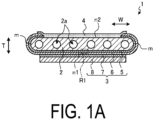
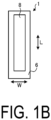
- the solid electrolyte layer 6 is an electrolyte and delivers ions between the fuel electrode layer 5 and the air electrode layer 8. At the same time, the solid electrolyte layer 6 has gas blocking properties, and makes leakage of the fuel gas and the oxygen-containing gas less likely to occur.
- the support body 15 includes an insertion hole 15a, into which the lower end portions of the plurality of cells 1 are inserted.
- the lower end portions of the plurality of cells 1 and the inner wall of the insertion hole 15a are bonded by the fixing material 13.
- electrically conductive members 18 are each interposed between adjacent ones of the cells 1 of the plurality of cells 1.
- Each of the electrically conductive members 18 electrically connects in series the fuel electrode layer 5 of one of the adjacent ones of the cells 1 with the air electrode layer 8 of the other one of the adjacent ones of the cells 1.
- the electrically conductive member 18 connects the interconnector 4 electrically connected to the fuel electrode layer 5 of the one of the adjacent ones of the cells 1 and the air electrode layer 8 of the other one of the adjacent ones of the cells 1.
- the interconnector 4 is made of metal or alloy
- the interconnector 4 and the electrically conductive member 18 may be integrated with each other, or the electrically conductive member 18 may also serve as the interconnector 4.
- the positive electrode terminal 19A functions as a positive electrode when the electrical power generated by the cell stack 11 is output to the outside, and is electrically connected to the end current collection member 17 on a positive electrode side in the cell stack 11A.
- the negative electrode terminal 19B functions as a negative electrode when the electrical power generated by the cell stack 11 is output to the outside, and is electrically connected to the end current collection member 17 on a negative electrode side in the cell stack 11B.
- the first part 5A contains the first material having high electron conductivity
- electrode activity and electrical conductivity of the fuel electrode layer 5 can be enhanced.
- the second part 5B is provided between the solid electrolyte layer 6 and the first part 5A in which the content proportion of the first material is higher than in the vicinity of the solid electrolyte layer 6 or higher than the content proportion of the second material, components derived from the first material are less likely to diffuse into the solid electrolyte layer 6, and a low-conductive reaction layer is less likely to be formed in the solid electrolyte layer 6 or at an interface between the solid electrolyte layer 6 and the fuel electrode layer 5.
- the thickness of the first part 5A may be smaller than the thickness of the second part 5B. Accordingly, the fuel gas easily permeates through the first part 5A located on the support substrate 2 side.
- the content proportion of the first material in the vicinity of the first surface may be higher than the content proportion of the first material in the vicinity of the second surface.
- the vicinity of the first surface is a region closer to the first surface than to the solid electrolyte layer 6 in the fuel electrode layer 5, and the vicinity of the second surface is a region closer to the solid electrolyte layer 6 than to the first surface in the fuel electrode layer 5.
- the average value of the content proportion of the first material may gradually decrease from the first surface to the second surface.
- FIG. 4 is an exterior perspective view illustrating a module according to the first embodiment.
- FIG. 4 illustrates a state in which the front and rear surfaces that are part of a storage container 101 are removed, and the cell stack device 10 of a fuel cell housed in the container is taken out rearward.
- the module 100 includes the storage container 101, and the cell stack device 10 housed in the storage container 101.
- the reformer 102 is disposed above the cell stack device 10.
- the above-discussed module 100 is configured such that the cell stack device 10 with improved power generation capability is housed therein as described above, whereby the module 100 with the improved power generation capability can be realized.
- FIG. 5 is an exploded perspective view illustrating an example of a module housing device according to the first embodiment.
- a module housing device 110 according to the present embodiment includes an external case 111, the module 100 illustrated in FIG. 4 , and an auxiliary device (not illustrated).
- the auxiliary device operates the module 100.
- the module 100 and the auxiliary device are housed in the external case 111. Note that in FIG. 5 , the configuration is partially omitted.
- the external case 111 of the module housing device 110 illustrated in FIG. 5 includes a support 112 and an external plate 113.
- a dividing plate 114 vertically partitions the interior of the external case 111.
- the space above the dividing plate 114 in the external case 111 is a module housing room 115 for housing the module 100.
- the space below the dividing plate 114 in the external case 111 is an auxiliary device housing room 116 for housing the auxiliary device configured to operate the module 100. Note that in FIG. 5 , the auxiliary device housed in the auxiliary device housing room 116 is omitted.
- the dividing plate 114 includes an air circulation hole 117 for causing air in the auxiliary device housing room 116 to flow into the module housing room 115 side.
- the external plate 113 constituting the module housing room 115 includes an exhaust hole 118 for discharging air inside the module housing room 115.
- the module 100 with improved power generation capability is provided in the module housing room 115 as described above, whereby the module housing device 110 with improved power generation capability can be realized.
- the embodiment described above the case where the support substrate of the hollow flat plate-shaped is used has been exemplified; however, the embodiment can also be applied to a cell stack device using a cylindrical support substrate.
- a so-called “vertically striped type” electrochemical cell device in which only one element portion including the fuel electrode layer, the solid electrolyte layer, and the air electrode layer is provided on the surface of the support substrate, is exemplified.
- the present disclosure can be applied to a horizontally striped type electrochemical cell device with an array of so-called “horizontally striped type” electrochemical cells, in which a plurality of element portions are provided on the surface of the support substrate at mutually separated locations, and adjacent element portions are electrically connected to each other.
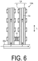
- FIG. 6 is a cross-sectional view illustrating an electrochemical cell device according to the second embodiment.
- FIG. 7 is a horizontal cross-sectional view illustrating an example of an electrochemical cell according to the second embodiment.
- a cell stack device 10A includes a plurality of cells 1A extending in the length direction L from a pipe 22a configured to distribute a fuel gas.
- the cell 1A includes a plurality of element portions 3 on a support substrate 2.
- the cells 1A are electrically connected to each other via connecting members 31.
- Each of the connecting members 31 is located between the element portions 3 each included in a corresponding one of the cells 1A and electrically connects adjacent ones of the cells 1A to each other.
- the connecting member 31 electrically connects the air electrode layer 8 of the element portion 3 of one of the adjacent ones of the cells 1A to the fuel electrode layer 5 of the element portion 3 of the other one of the adjacent ones of the cells 1A.
- the cell 1A includes a support substrate 2, a pair of element portions 3, and a sealing portion 30.
- the support substrate 2 has a pillar shape having a first surface n1 and a second surface n2 which are a pair of flat surfaces and face each other, and a pair of arc-shaped side surfaces m that connect the first surface n1 and the second surface n2.
- the pair of element portions 3 are located on the first surface n1 and the second surface n2 of the support substrate 2 so as to face each other.
- the sealing portion 30 is located to cover the side surface m of the support substrate 2.
- the cell 1A has a shape that is symmetric with respect to a plane that passes through a center in the thickness direction T and is parallel to the main surface of the support substrate 2.
- the element portion 3 includes a fuel electrode layer 5, a solid electrolyte layer 6, an intermediate layer 7, and an air electrode layer 8 layered in that order.
- FIG. 8 is an enlarged cross-sectional view of the region R2 indicated in FIG. 7 .
- the fuel electrode layer 5 includes a second part 5B and a first part 5A located in sequence from the solid electrolyte layer 6 side.
- the solid electrolyte layer 6 contains Zr.
- the fuel electrode layer 5 includes the first part 5A containing the first material and the second part 5B located between the first part 5A and the solid electrolyte layer 6. Accordingly, the electrode activity and electrical conductivity of the fuel electrode layer 5 can be enhanced.
- the content proportion of the first material in the vicinity of the first surface of fuel electrode layer 5 located on the side opposite to the solid electrolyte layer 6 may be higher than the content proportion of the first material in the vicinity of the second surface in contact with the solid electrolyte layer 6.
- the cell 1A can improve power generation capability.
- FIG. 9A is a perspective view illustrating an example of an electrochemical cell according to a third embodiment.
- FIG. 9B is a partial cross-sectional view of the electrochemical cell illustrated in FIG. 9A .
- the support member 94 may be a so-called separator that separates the flow passage 98 of the fuel gas and the flow passage 97 of the oxygen-containing gas.
- the material of the support members 94 and 95 may be, for example, an electrically conductive metal, or may be an insulating ceramic.
- both the support members 94 and 95 may be metal, or one of the support members 94 and 95 may be an insulating material.
- the bonding material 93 is an electrically conductive metal
- both or one of the support members 94 and 95 may be an insulating material.
- the support members 94 and 95 are metal, the support members 94 and 95 may be formed integrally with the electrically conductive member 92.
- One of the bonding material 93 and the support members 94 and 95 has insulating properties and causes the two electrically conductive members 91 and 92 sandwiching the flat plate cell to be electrically insulated from each other.
- FIG. 9C is an enlarged cross-sectional view of a region R3 indicated in FIG. 9B .
- the fuel electrode layer 5 includes a second part 5B and a first part 5A located in sequence from the solid electrolyte layer 6 side.
- the solid electrolyte layer 6 contains Zr.
- the fuel electrode layer 5 includes the first part 5A containing the first material and the second part 5B located between the first part 5A and the solid electrolyte layer 6. Accordingly, the electrode activity and electrical conductivity of the fuel electrode layer 5 can be enhanced.
- the content proportion of the first material in the vicinity of the first surface of fuel electrode layer 5 located on the side opposite to the solid electrolyte layer 6 may be higher than the content proportion of the first material in the vicinity of the second surface in contact with the solid electrolyte layer 6.
- the cell 1B can improve power generation capability.
- FIG. 10A is a horizontal cross-sectional view illustrating an example of an electrochemical cell according to a fourth embodiment.
- FIGs. 10B and 10C are horizontal cross-sectional views illustrating another example of the electrochemical cell according to the fourth embodiment.
- FIG. 11 is an enlarged view of the region R4 illustrated in FIG. 10A . Note that FIG. 11 can also be applied to the examples in FIGs. 10B and 10C .
- a cell 1C includes an element portion 3C in which a fuel electrode layer 5, a solid electrolyte layer 6, an intermediate layer 7, and an air electrode layer 8 are layered, and a support substrate 2.
- the support substrate 2 includes through holes or fine holes at a site in contact with the element portion 3, and includes a member 120 located outside the gas-flow passage 2a.
- the support substrate 2 allows gas to flow between the gas-flow passage 2a and the element portion 3C.
- the support substrate 2 may be made of, for example, one or more metal plates. A material of the metal plate may contain chromium.
- the metal plate may include a conductive coating layer.
- the support substrate 2 electrically connects adjacent ones of the cells 1C to each other.
- the element portion 3C may be directly formed on the support substrate 2 or may be bonded to the support substrate 2 by a bonding material.
- the side surface of the fuel electrode layer 5 is covered with the solid electrolyte layer 6 to hermetically seal the gas-flow passage 2a through which the fuel gas flows.
- the side surface of the fuel electrode layer 5 may be covered and sealed with a sealing material 9 made of dense glass or ceramic.
- the sealing material 9 covering the side surface of the fuel electrode layer 5 may have electrical insulation properties.
- the gas-flow passage 2a of the support substrate 2 may be made of the member 120 having unevenness as illustrated in FIG. 10C .
- FIG. 11 is an enlarged cross-sectional view of the region R4 indicated in FIG. 10A .
- the fuel electrode layer 5 includes a second part 5B and a first part 5A located in sequence from the solid electrolyte layer 6 side.
- the solid electrolyte layer 6 contains Zr.
- the fuel electrode layer 5 includes the first part 5A containing the first material and the second part 5B located between the first part 5A and the solid electrolyte layer 6. Accordingly, the electrode activity and electrical conductivity of the fuel electrode layer 5 can be enhanced.
- the content proportion of the first material in the vicinity of the first surface of fuel electrode layer 5 located on the side opposite to the solid electrolyte layer 6 may be higher than the content proportion of the first material in the vicinity of the second surface in contact with the solid electrolyte layer 6.
- the cell 1C can improve power generation capability.
- a fuel cell, a fuel cell stack device, a fuel cell module, and a fuel cell device are illustrated as examples of the "electrochemical cell”, the “electrochemical cell device”, the “module”, and the “module housing device”; other examples include an electrolytic cell, an electrolytic cell stack device, an electrolytic module, and an electrolytic device, respectively.
- the electrolytic cell includes a first electrode layer and a second electrode layer, and decomposes water vapor into hydrogen and oxygen or decomposes carbon dioxide into carbon monoxide and oxygen by supplying electric power.
- the electrolyte material may be a hydroxide ion conductor. According to the electrolytic cell, electrolytic cell stack device, electrolytic module, and electrolytic device discussed above, electrolytic performance can be improved.
- the electrochemical cell (cell 1) includes the first electrode layer (fuel electrode layer 5), the second electrode layer (air electrode layer 8), and the solid electrolyte layer 6.
- the first electrode layer includes the first material and the second material having ion conductivity.
- the solid electrolyte layer 6 is located between the first electrode layer and the second electrode layer, and contains Zr.
- the first material has a higher electron conductivity than the second material.
- the first electrode layer includes the first part 5A containing the first material and the second part 5B located between the first part 5A and the solid electrolyte layer 6. This can improve the cell performance such as power generation capability and electrolytic performance of the electrochemical cell.
- the electrochemical cell device (cell stack device 10) according to the present embodiment includes the cell stack 11 containing the electrochemical cell described above. This can improve the cell performance such as power generation capability and electrolytic performance of the electrochemical cell device.
Landscapes
- Chemical & Material Sciences (AREA)
- Engineering & Computer Science (AREA)
- Electrochemistry (AREA)
- Chemical Kinetics & Catalysis (AREA)
- General Chemical & Material Sciences (AREA)
- Manufacturing & Machinery (AREA)
- Life Sciences & Earth Sciences (AREA)
- Sustainable Development (AREA)
- Sustainable Energy (AREA)
- Materials Engineering (AREA)
- Composite Materials (AREA)
- Fuel Cell (AREA)
- Inert Electrodes (AREA)
Applications Claiming Priority (2)
| Application Number | Priority Date | Filing Date | Title |
|---|---|---|---|
| JP2021161460 | 2021-09-30 | ||
| PCT/JP2022/036225 WO2023054494A1 (ja) | 2021-09-30 | 2022-09-28 | 電気化学セル、電気化学セル装置、モジュールおよびモジュール収容装置 |
Publications (2)
| Publication Number | Publication Date |
|---|---|
| EP4394958A1 true EP4394958A1 (de) | 2024-07-03 |
| EP4394958A4 EP4394958A4 (de) | 2025-10-08 |
Family
ID=85780724
Family Applications (1)
| Application Number | Title | Priority Date | Filing Date |
|---|---|---|---|
| EP22876360.3A Pending EP4394958A4 (de) | 2021-09-30 | 2022-09-28 | Elektrochemische zelle, elektrochemische zellenvorrichtung, modul und modulspeichervorrichtung |
Country Status (5)
| Country | Link |
|---|---|
| US (1) | US20240387849A1 (de) |
| EP (1) | EP4394958A4 (de) |
| JP (2) | JP7284355B1 (de) |
| CN (1) | CN117999681A (de) |
| WO (1) | WO2023054494A1 (de) |
Families Citing this family (4)
| Publication number | Priority date | Publication date | Assignee | Title |
|---|---|---|---|---|
| WO2025017499A1 (en) | 2023-07-17 | 2025-01-23 | Graviton Bioscience Bv | Formulations and uses of rock2 inhibitors for als |
| WO2025070717A1 (ja) * | 2023-09-27 | 2025-04-03 | 京セラ株式会社 | 電気化学セル、電気化学セル装置、モジュールおよびモジュール収容装置 |
| WO2025094956A1 (ja) * | 2023-10-30 | 2025-05-08 | 京セラ株式会社 | 電気化学セル、電気化学セル装置、モジュールおよびモジュール収容装置 |
| WO2025206301A1 (ja) * | 2024-03-29 | 2025-10-02 | 京セラ株式会社 | 電気化学セル、電気化学セル装置、モジュールおよびモジュール収容装置 |
Family Cites Families (11)
| Publication number | Priority date | Publication date | Assignee | Title |
|---|---|---|---|---|
| JP3319136B2 (ja) * | 1994-03-16 | 2002-08-26 | 東陶機器株式会社 | 固体電解質燃料電池 |
| JPH09129245A (ja) * | 1995-10-31 | 1997-05-16 | Kyocera Corp | 固体電解質型燃料電池セル |
| JPH103930A (ja) * | 1996-04-19 | 1998-01-06 | Tokyo Gas Co Ltd | 固体電解質型燃料電池の燃料極の作製方法 |
| EP2530771B1 (de) * | 2010-01-27 | 2016-08-10 | NGK Insulators, Ltd. | Brennstoffzelle |
| DK2748884T3 (da) | 2011-08-25 | 2020-02-17 | Univ Florida | Fastoxid-brændselscelle med komposit-anode med forbedret mekanisk integritet og forøget effektitivet |
| KR101685386B1 (ko) * | 2014-07-22 | 2016-12-13 | 한국과학기술연구원 | 저온 동시소결에 의한 연료극 지지형 고체산화물 셀 및 그 제조방법 |
| JP7063433B2 (ja) * | 2016-03-18 | 2022-05-09 | レドックス パワー システムズ, エルエルシー | カソード機能層を有する固体酸化物燃料電池 |
| JP6734816B2 (ja) * | 2017-06-21 | 2020-08-05 | 日本特殊陶業株式会社 | 電気化学セルおよび電気化学スタック |
| WO2019240297A1 (ja) * | 2018-06-15 | 2019-12-19 | 京セラ株式会社 | セル、セルスタック装置、モジュール及びモジュール収納装置 |
| JP7075368B2 (ja) * | 2019-04-01 | 2022-05-25 | 株式会社豊田中央研究所 | 固体酸化物形燃料電池用アノード |
| JP7360276B2 (ja) * | 2019-08-30 | 2023-10-12 | 太陽誘電株式会社 | 固体酸化物型燃料電池およびその製造方法 |
-
2022
- 2022-09-28 JP JP2022577649A patent/JP7284355B1/ja active Active
- 2022-09-28 EP EP22876360.3A patent/EP4394958A4/de active Pending
- 2022-09-28 WO PCT/JP2022/036225 patent/WO2023054494A1/ja not_active Ceased
- 2022-09-28 CN CN202280063994.4A patent/CN117999681A/zh active Pending
- 2022-09-28 US US18/693,920 patent/US20240387849A1/en active Pending
-
2023
- 2023-05-18 JP JP2023082119A patent/JP2023096113A/ja active Pending
Also Published As
| Publication number | Publication date |
|---|---|
| JPWO2023054494A1 (de) | 2023-04-06 |
| JP2023096113A (ja) | 2023-07-06 |
| JP7284355B1 (ja) | 2023-05-30 |
| CN117999681A (zh) | 2024-05-07 |
| EP4394958A4 (de) | 2025-10-08 |
| US20240387849A1 (en) | 2024-11-21 |
| WO2023054494A1 (ja) | 2023-04-06 |
Similar Documents
| Publication | Publication Date | Title |
|---|---|---|
| EP4394958A1 (de) | Elektrochemische zelle, elektrochemische zellenvorrichtung, modul und modulspeichervorrichtung | |
| JP7197747B2 (ja) | セル、セルスタック装置、モジュールおよびモジュール収容装置 | |
| JP2023109462A (ja) | 電気化学セル、電気化学セル装置、モジュールおよびモジュール収容装置 | |
| EP4432404A1 (de) | Elektrochemische zellenvorrichtung, modul und modulaufnahmevorrichtung | |
| EP4404312A1 (de) | Elektrochemische zelle, elektrochemische zellenvorrichtung, modul und modulspeichervorrichtung | |
| EP4489151A1 (de) | Elektrochemische zelle, elektrochemische zellenvorrichtung, modul und modulaufnahmevorrichtung | |
| EP4597649A1 (de) | Elektrochemische zelle, elektrochemische zellenvorrichtung, modul und modulaufnahmevorrichtung | |
| EP4571907A1 (de) | Elektrochemische zelle, elektrochemische zellenvorrichtung, modul und modulaufnahmevorrichtung | |
| EP4715914A1 (de) | Festelektrolytschicht, elektrochemische zelle, elektrochemische zellenvorrichtung, modul und modulspeichervorrichtung | |
| EP4708415A1 (de) | Elektrisch leitendes element, elektrochemische zellenvorrichtung, modul und modulaufnahmevorrichtung | |
| EP4641719A1 (de) | Festelektrolytschicht, elektrochemische zelle, elektrochemische zellenvorrichtung, modul und modulspeichervorrichtung | |
| WO2024117052A1 (ja) | 複合部材、電気化学セル、電気化学セル装置、モジュールおよびモジュール収容装置 | |
| WO2024247989A1 (ja) | 電気化学セル、電気化学セル装置、モジュールおよびモジュール収容装置 | |
| WO2024150829A1 (ja) | 電気化学セル、電気化学セル装置、モジュールおよびモジュール収容装置 | |
| WO2024143355A1 (ja) | 電気化学セル、電気化学セル装置、モジュールおよびモジュール収容装置 | |
| WO2026029158A1 (ja) | 電気化学セル、電気化学セル装置、モジュールおよびモジュール収容装置 | |
| JP2025153056A (ja) | 電気化学セル、電気化学セル装置、モジュールおよびモジュール収容装置 | |
| WO2025094956A1 (ja) | 電気化学セル、電気化学セル装置、モジュールおよびモジュール収容装置 | |
| JP2024048859A (ja) | 電気化学セル装置、モジュールおよびモジュール収容装置 | |
| WO2026048889A1 (ja) | 電気化学セル、電気化学セル装置、モジュールおよびモジュール収容装置 | |
| JP2023006816A (ja) | セル、セルスタック装置、モジュールおよびモジュール収容装置 |
Legal Events
| Date | Code | Title | Description |
|---|---|---|---|
| STAA | Information on the status of an ep patent application or granted ep patent |
Free format text: STATUS: THE INTERNATIONAL PUBLICATION HAS BEEN MADE |
|
| PUAI | Public reference made under article 153(3) epc to a published international application that has entered the european phase |
Free format text: ORIGINAL CODE: 0009012 |
|
| STAA | Information on the status of an ep patent application or granted ep patent |
Free format text: STATUS: REQUEST FOR EXAMINATION WAS MADE |
|
| 17P | Request for examination filed |
Effective date: 20240327 |
|
| AK | Designated contracting states |
Kind code of ref document: A1 Designated state(s): AL AT BE BG CH CY CZ DE DK EE ES FI FR GB GR HR HU IE IS IT LI LT LU LV MC MK MT NL NO PL PT RO RS SE SI SK SM TR |
|
| DAV | Request for validation of the european patent (deleted) | ||
| DAX | Request for extension of the european patent (deleted) | ||
| A4 | Supplementary search report drawn up and despatched |
Effective date: 20250905 |
|
| RIC1 | Information provided on ipc code assigned before grant |
Ipc: H01M 8/1213 20160101AFI20250901BHEP Ipc: H01M 4/86 20060101ALI20250901BHEP Ipc: H01M 8/04 20160101ALI20250901BHEP Ipc: H01M 8/12 20160101ALI20250901BHEP Ipc: H01M 8/1253 20160101ALI20250901BHEP Ipc: H01M 8/2475 20160101ALI20250901BHEP Ipc: H01M 4/90 20060101ALI20250901BHEP Ipc: H01M 8/00 20160101ALI20250901BHEP |