EP4397167A2 - Autonome maschinennavigation und training mit sichtsystem - Google Patents
Autonome maschinennavigation und training mit sichtsystem Download PDFInfo
- Publication number
- EP4397167A2 EP4397167A2 EP24170502.9A EP24170502A EP4397167A2 EP 4397167 A2 EP4397167 A2 EP 4397167A2 EP 24170502 A EP24170502 A EP 24170502A EP 4397167 A2 EP4397167 A2 EP 4397167A2
- Authority
- EP
- European Patent Office
- Prior art keywords
- data
- work region
- autonomous machine
- pose
- training
- Prior art date
- Legal status (The legal status is an assumption and is not a legal conclusion. Google has not performed a legal analysis and makes no representation as to the accuracy of the status listed.)
- Pending
Links
Images


Classifications
-
- A—HUMAN NECESSITIES
- A01—AGRICULTURE; FORESTRY; ANIMAL HUSBANDRY; HUNTING; TRAPPING; FISHING
- A01D—HARVESTING; MOWING
- A01D34/00—Mowers; Mowing apparatus of harvesters
- A01D34/006—Control or measuring arrangements
- A01D34/008—Control or measuring arrangements for automated or remotely controlled operation
-
- A—HUMAN NECESSITIES
- A01—AGRICULTURE; FORESTRY; ANIMAL HUSBANDRY; HUNTING; TRAPPING; FISHING
- A01D—HARVESTING; MOWING
- A01D34/00—Mowers; Mowing apparatus of harvesters
- A01D34/01—Mowers; Mowing apparatus of harvesters characterised by features relating to the type of cutting apparatus
- A01D34/412—Mowers; Mowing apparatus of harvesters characterised by features relating to the type of cutting apparatus having rotating cutters
- A01D34/63—Mowers; Mowing apparatus of harvesters characterised by features relating to the type of cutting apparatus having rotating cutters having cutters rotating about a vertical axis
- A01D34/82—Other details
- A01D34/824—Handle arrangements
-
- G—PHYSICS
- G01—MEASURING; TESTING
- G01C—MEASURING DISTANCES, LEVELS OR BEARINGS; SURVEYING; NAVIGATION; GYROSCOPIC INSTRUMENTS; PHOTOGRAMMETRY OR VIDEOGRAMMETRY
- G01C21/00—Navigation; Navigational instruments not provided for in groups G01C1/00 - G01C19/00
- G01C21/38—Electronic maps specially adapted for navigation; Updating thereof
- G01C21/3804—Creation or updating of map data
- G01C21/3833—Creation or updating of map data characterised by the source of data
- G01C21/3848—Data obtained from both position sensors and additional sensors
-
- G—PHYSICS
- G01—MEASURING; TESTING
- G01C—MEASURING DISTANCES, LEVELS OR BEARINGS; SURVEYING; NAVIGATION; GYROSCOPIC INSTRUMENTS; PHOTOGRAMMETRY OR VIDEOGRAMMETRY
- G01C21/00—Navigation; Navigational instruments not provided for in groups G01C1/00 - G01C19/00
- G01C21/38—Electronic maps specially adapted for navigation; Updating thereof
- G01C21/3863—Structures of map data
- G01C21/3867—Geometry of map features, e.g. shape points, polygons or for simplified maps
-
- G—PHYSICS
- G05—CONTROLLING; REGULATING
- G05D—SYSTEMS FOR CONTROLLING OR REGULATING NON-ELECTRIC VARIABLES
- G05D1/00—Control of position, course, altitude or attitude of land, water, air or space vehicles, e.g. using automatic pilots
- G05D1/0055—Control of position, course, altitude or attitude of land, water, air or space vehicles, e.g. using automatic pilots with safety arrangements
- G05D1/0061—Control of position, course, altitude or attitude of land, water, air or space vehicles, e.g. using automatic pilots with safety arrangements for transition from automatic pilot to manual pilot and vice versa
-
- G—PHYSICS
- G05—CONTROLLING; REGULATING
- G05D—SYSTEMS FOR CONTROLLING OR REGULATING NON-ELECTRIC VARIABLES
- G05D1/00—Control of position, course, altitude or attitude of land, water, air or space vehicles, e.g. using automatic pilots
- G05D1/0088—Control of position, course, altitude or attitude of land, water, air or space vehicles, e.g. using automatic pilots characterized by the autonomous decision making process, e.g. artificial intelligence, predefined behaviours
-
- G—PHYSICS
- G05—CONTROLLING; REGULATING
- G05D—SYSTEMS FOR CONTROLLING OR REGULATING NON-ELECTRIC VARIABLES
- G05D1/00—Control of position, course, altitude or attitude of land, water, air or space vehicles, e.g. using automatic pilots
- G05D1/02—Control of position or course in two dimensions
- G05D1/021—Control of position or course in two dimensions specially adapted to land vehicles
- G05D1/0212—Control of position or course in two dimensions specially adapted to land vehicles with means for defining a desired trajectory
- G05D1/0221—Control of position or course in two dimensions specially adapted to land vehicles with means for defining a desired trajectory involving a learning process
-
- G—PHYSICS
- G05—CONTROLLING; REGULATING
- G05D—SYSTEMS FOR CONTROLLING OR REGULATING NON-ELECTRIC VARIABLES
- G05D1/00—Control of position, course, altitude or attitude of land, water, air or space vehicles, e.g. using automatic pilots
- G05D1/02—Control of position or course in two dimensions
- G05D1/021—Control of position or course in two dimensions specially adapted to land vehicles
- G05D1/0231—Control of position or course in two dimensions specially adapted to land vehicles using optical position detecting means
- G05D1/0246—Control of position or course in two dimensions specially adapted to land vehicles using optical position detecting means using a video camera in combination with image processing means
-
- G—PHYSICS
- G05—CONTROLLING; REGULATING
- G05D—SYSTEMS FOR CONTROLLING OR REGULATING NON-ELECTRIC VARIABLES
- G05D1/00—Control of position, course, altitude or attitude of land, water, air or space vehicles, e.g. using automatic pilots
- G05D1/02—Control of position or course in two dimensions
- G05D1/021—Control of position or course in two dimensions specially adapted to land vehicles
- G05D1/0268—Control of position or course in two dimensions specially adapted to land vehicles using internal positioning means
- G05D1/027—Control of position or course in two dimensions specially adapted to land vehicles using internal positioning means comprising intertial navigation means, e.g. azimuth detector
-
- G—PHYSICS
- G05—CONTROLLING; REGULATING
- G05D—SYSTEMS FOR CONTROLLING OR REGULATING NON-ELECTRIC VARIABLES
- G05D1/00—Control of position, course, altitude or attitude of land, water, air or space vehicles, e.g. using automatic pilots
- G05D1/02—Control of position or course in two dimensions
- G05D1/021—Control of position or course in two dimensions specially adapted to land vehicles
- G05D1/0268—Control of position or course in two dimensions specially adapted to land vehicles using internal positioning means
- G05D1/0274—Control of position or course in two dimensions specially adapted to land vehicles using internal positioning means using mapping information stored in a memory device
-
- G—PHYSICS
- G05—CONTROLLING; REGULATING
- G05D—SYSTEMS FOR CONTROLLING OR REGULATING NON-ELECTRIC VARIABLES
- G05D1/00—Control of position, course, altitude or attitude of land, water, air or space vehicles, e.g. using automatic pilots
- G05D1/20—Control system inputs
- G05D1/22—Command input arrangements
- G05D1/221—Remote-control arrangements
- G05D1/227—Handing over between remote control and on-board control; Handing over between remote control arrangements
-
- G—PHYSICS
- G05—CONTROLLING; REGULATING
- G05D—SYSTEMS FOR CONTROLLING OR REGULATING NON-ELECTRIC VARIABLES
- G05D1/00—Control of position, course, altitude or attitude of land, water, air or space vehicles, e.g. using automatic pilots
- G05D1/20—Control system inputs
- G05D1/24—Arrangements for determining position or orientation
- G05D1/243—Means capturing signals occurring naturally from the environment, e.g. ambient optical, acoustic, gravitational or magnetic signals
-
- G—PHYSICS
- G05—CONTROLLING; REGULATING
- G05D—SYSTEMS FOR CONTROLLING OR REGULATING NON-ELECTRIC VARIABLES
- G05D1/00—Control of position, course, altitude or attitude of land, water, air or space vehicles, e.g. using automatic pilots
- G05D1/20—Control system inputs
- G05D1/24—Arrangements for determining position or orientation
- G05D1/245—Arrangements for determining position or orientation using dead reckoning
-
- G—PHYSICS
- G05—CONTROLLING; REGULATING
- G05D—SYSTEMS FOR CONTROLLING OR REGULATING NON-ELECTRIC VARIABLES
- G05D1/00—Control of position, course, altitude or attitude of land, water, air or space vehicles, e.g. using automatic pilots
- G05D1/20—Control system inputs
- G05D1/24—Arrangements for determining position or orientation
- G05D1/246—Arrangements for determining position or orientation using environment maps, e.g. simultaneous localisation and mapping [SLAM]
-
- G—PHYSICS
- G05—CONTROLLING; REGULATING
- G05D—SYSTEMS FOR CONTROLLING OR REGULATING NON-ELECTRIC VARIABLES
- G05D1/00—Control of position, course, altitude or attitude of land, water, air or space vehicles, e.g. using automatic pilots
- G05D1/20—Control system inputs
- G05D1/24—Arrangements for determining position or orientation
- G05D1/247—Arrangements for determining position or orientation using signals provided by artificial sources external to the vehicle, e.g. navigation beacons
- G05D1/249—Arrangements for determining position or orientation using signals provided by artificial sources external to the vehicle, e.g. navigation beacons from positioning sensors located off-board the vehicle, e.g. from cameras
-
- G—PHYSICS
- G05—CONTROLLING; REGULATING
- G05D—SYSTEMS FOR CONTROLLING OR REGULATING NON-ELECTRIC VARIABLES
- G05D1/00—Control of position, course, altitude or attitude of land, water, air or space vehicles, e.g. using automatic pilots
- G05D1/40—Control within particular dimensions
- G05D1/43—Control of position or course in two dimensions [2D]
-
- G—PHYSICS
- G05—CONTROLLING; REGULATING
- G05D—SYSTEMS FOR CONTROLLING OR REGULATING NON-ELECTRIC VARIABLES
- G05D1/00—Control of position, course, altitude or attitude of land, water, air or space vehicles, e.g. using automatic pilots
- G05D1/60—Intended control result
- G05D1/646—Following a predefined trajectory, e.g. a line marked on the floor or a flight path
-
- G—PHYSICS
- G06—COMPUTING OR CALCULATING; COUNTING
- G06N—COMPUTING ARRANGEMENTS BASED ON SPECIFIC COMPUTATIONAL MODELS
- G06N3/00—Computing arrangements based on biological models
- G06N3/02—Neural networks
- G06N3/08—Learning methods
-
- G—PHYSICS
- G06—COMPUTING OR CALCULATING; COUNTING
- G06V—IMAGE OR VIDEO RECOGNITION OR UNDERSTANDING
- G06V10/00—Arrangements for image or video recognition or understanding
- G06V10/40—Extraction of image or video features
- G06V10/46—Descriptors for shape, contour or point-related descriptors, e.g. scale invariant feature transform [SIFT] or bags of words [BoW]; Salient regional features
- G06V10/462—Salient features, e.g. scale invariant feature transforms [SIFT]
-
- G—PHYSICS
- G06—COMPUTING OR CALCULATING; COUNTING
- G06V—IMAGE OR VIDEO RECOGNITION OR UNDERSTANDING
- G06V10/00—Arrangements for image or video recognition or understanding
- G06V10/70—Arrangements for image or video recognition or understanding using pattern recognition or machine learning
- G06V10/74—Image or video pattern matching; Proximity measures in feature spaces
- G06V10/75—Organisation of the matching processes, e.g. simultaneous or sequential comparisons of image or video features; Coarse-fine approaches, e.g. multi-scale approaches; using context analysis; Selection of dictionaries
- G06V10/757—Matching configurations of points or features
-
- G—PHYSICS
- G06—COMPUTING OR CALCULATING; COUNTING
- G06V—IMAGE OR VIDEO RECOGNITION OR UNDERSTANDING
- G06V20/00—Scenes; Scene-specific elements
- G06V20/10—Terrestrial scenes
-
- G—PHYSICS
- G06—COMPUTING OR CALCULATING; COUNTING
- G06V—IMAGE OR VIDEO RECOGNITION OR UNDERSTANDING
- G06V20/00—Scenes; Scene-specific elements
- G06V20/60—Type of objects
- G06V20/64—Three-dimensional [3D] objects
-
- A—HUMAN NECESSITIES
- A01—AGRICULTURE; FORESTRY; ANIMAL HUSBANDRY; HUNTING; TRAPPING; FISHING
- A01D—HARVESTING; MOWING
- A01D2101/00—Lawn-mowers
-
- A—HUMAN NECESSITIES
- A01—AGRICULTURE; FORESTRY; ANIMAL HUSBANDRY; HUNTING; TRAPPING; FISHING
- A01D—HARVESTING; MOWING
- A01D34/00—Mowers; Mowing apparatus of harvesters
- A01D34/01—Mowers; Mowing apparatus of harvesters characterised by features relating to the type of cutting apparatus
- A01D34/412—Mowers; Mowing apparatus of harvesters characterised by features relating to the type of cutting apparatus having rotating cutters
- A01D34/63—Mowers; Mowing apparatus of harvesters characterised by features relating to the type of cutting apparatus having rotating cutters having cutters rotating about a vertical axis
- A01D34/67—Mowers; Mowing apparatus of harvesters characterised by features relating to the type of cutting apparatus having rotating cutters having cutters rotating about a vertical axis hand-guided by a walking operator
- A01D34/68—Mowers; Mowing apparatus of harvesters characterised by features relating to the type of cutting apparatus having rotating cutters having cutters rotating about a vertical axis hand-guided by a walking operator with motor driven cutters or wheels
- A01D34/69—Mowers; Mowing apparatus of harvesters characterised by features relating to the type of cutting apparatus having rotating cutters having cutters rotating about a vertical axis hand-guided by a walking operator with motor driven cutters or wheels with motor driven wheels
-
- A—HUMAN NECESSITIES
- A01—AGRICULTURE; FORESTRY; ANIMAL HUSBANDRY; HUNTING; TRAPPING; FISHING
- A01D—HARVESTING; MOWING
- A01D34/00—Mowers; Mowing apparatus of harvesters
- A01D34/01—Mowers; Mowing apparatus of harvesters characterised by features relating to the type of cutting apparatus
- A01D34/412—Mowers; Mowing apparatus of harvesters characterised by features relating to the type of cutting apparatus having rotating cutters
- A01D34/63—Mowers; Mowing apparatus of harvesters characterised by features relating to the type of cutting apparatus having rotating cutters having cutters rotating about a vertical axis
- A01D34/76—Driving mechanisms for the cutters
- A01D34/78—Driving mechanisms for the cutters electric
-
- G—PHYSICS
- G05—CONTROLLING; REGULATING
- G05D—SYSTEMS FOR CONTROLLING OR REGULATING NON-ELECTRIC VARIABLES
- G05D2111/00—Details of signals used for control of position, course, altitude or attitude of land, water, air or space vehicles
- G05D2111/50—Internal signals, i.e. from sensors located in the vehicle, e.g. from compasses or angular sensors
Definitions
- the present disclosure relates to autonomous machine navigation.
- the present disclosure relates to autonomous machine navigation for grounds maintenance machines.
- Grounds maintenance machines such as lawn and garden machines, are known for performing a variety of tasks.
- powered lawn mowers are used by both homeowners and professionals alike to maintain grass areas within a property or yard.
- Lawn mowers that autonomously perform the grass cutting function are also known.
- Some lawn mowers will operate in a work region within a predefined boundary. Such lawn mowers may rely upon navigation systems that help the lawn mower autonomously stay within the predefined boundary. For example, some boundaries are defined by wires, which are detected by the mower. The mower navigates by moving randomly within the boundary and redirect its trajectory upon detecting the boundary wire. Using boundary wires may be undesirable for some work regions or some autonomous maintenance tasks.
- the boundary wire may be costly and cumbersome to install, may break and become inoperable, or may be difficult to move to redefine a desirable boundary for the work region.
- the mobile nature of lawn mowers has limited the available computing resources, such as processing power, memory capabilities, and battery life, available to the lawn mower for other, more sophisticated types of navigation.
- Embodiments of the present disclosure relate to navigation for autonomous machines, particularly to autonomously navigate and operate within a boundary of a work region, and even more particularly may be suitable for autonomous machines with limited computing resources.
- the techniques of the present disclosure provide a robust process for training an autonomous machine for navigation in a work region.
- a method for autonomous machine navigation includes determining a current pose of an autonomous machine based on non-vision-based pose data captured by one or more non-vision-based sensors of the autonomous machine.
- the pose represents one or both of a position and an orientation of the autonomous machine in a work region defined by one or more boundaries.
- the method also includes determining vision-based pose data based on image data captured by the autonomous machine.
- the method further includes updating the current pose based on the vision-based pose data to correct or localize the current pose and to provide an updated pose of the autonomous machine in the work region for navigating the autonomous machine in the work region.
- an autonomous machine in another aspect, includes a housing coupled to a maintenance implement; a set of wheels supporting the housing over a ground surface; a propulsion controller operably coupled to the set of wheels; a vision system having at least one camera adapted to capture image data; and a navigation system operably coupled to the vision system and the propulsion controller.
- the navigation system is adapted to direct the autonomous machine within the work region.
- the navigation system may be configured to determine a current pose of an autonomous machine based on non-vision-based pose data captured by one or more non-vision-based sensors of the autonomous machine.
- the pose represents one or both of a position and an orientation of the autonomous machine in the work region defined by one or more boundaries.
- the navigation system may be configured to include determining vision-based pose data based on image data captured by the at least one camera.
- the navigation system may be configured to update the current pose based on the vision-based pose data to correct or localize the current pose and to provide an updated pose of the autonomous machine in the work region for navigating the autonomous machine in the work region.
- a method of navigation training for an autonomous machine may include directing the autonomous machine during a touring phase of a training mode along at least one of a perimeter or an interior of a work region to record a first set of touring images associated with the perimeter or a second set of touring images associated with the interior; generating during an offline mode a three-dimensional point cloud (3DPC) based on at least one of the first set and the second set of touring images; and directing the autonomous machine during a mapping phase of the training mode along one or more paths to record sensor fusion data to define one or more boundaries for the work region in a navigational map.
- 3DPC three-dimensional point cloud
- Some aspects described herein relate to defining a boundary of a work region using a vision system and a non-vision-based sensor. Some aspects of the present disclosure relate to correcting an estimated position within the work region using a vision system.
- the vision system may utilize one or more cameras. Images may be recorded by directing the autonomous machine along a desired boundary path (e.g., during a training mode). Algorithms may be used to extract features, to match features between different images, and to generate a three-dimensional point cloud (3DPC, or 3D point cloud) corresponding to at least the work region (e.g., during an offline mode).
- 3DPC three-dimensional point cloud
- Positions and orientations of the autonomous machine during image recording may be determined for various points in the 3DPC, for example, based on the positions of various points in the 3DPC and positions of the corresponding features in the recorded images. Positions and orientations may also be recovered directly during generation of the point cloud. At least the position information may be used to determine a boundary for the work region for subsequent navigation of the autonomous machine in the work region.
- the vision machine may record operational images and determine a vision-based position and orientation of the autonomous machine.
- the vision-based position may be used to update, or correct errors in, a determined or estimated position based on non-vision-based sensors.
- Various aspects described herein relate to utilizing limited computing resources while achieving suitable navigation of the work region.
- the processing of recorded images may occur during an offline mode, for example, when the autonomous machine is charging overnight.
- the vision system may be used at a low refresh rate to complement a high refresh rate non-vision-based navigation system.
- autonomous mower While described herein in illustrative examples as an autonomous mower, such a configuration is illustrative only as systems and methods described herein also have application to other autonomous machines including, for example, commercial mowing products (e.g., riding fairway or greens mowers that are driven by a user), other ground working machines or vehicles (e.g., debris blowers/vacuums, aerators, dethatchers, material spreaders, snow throwers, weeding machines for weed remediation), indoor working vehicles such as vacuums and floor scrubbers/cleaners (e.g., that may encounter obstacles), construction and utility vehicles (e.g., trenchers), observation vehicles, and load transportation (e.g., including people and things, such as people movers and hauling equipment).
- the autonomous machines described herein may employ various one or more types of navigation, such as random, modified random, or specific path planning, to carry out their intended functionality.
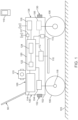
- relative terms such as “left,” “right,” “front,” “fore,” “forward,” “rear,” “aft,” “rearward,” “top,” “bottom,” “side,” “upper,” “lower,” “above,” “below,” “horizontal,” “vertical,” and the like may be used herein and, if so, are from the perspective shown in the particular figure, or while the machine 100 is in an operating configuration (e.g., while the machine 100 is positioned such that wheels 106 and 108 rest upon a generally horizontal ground surface 103 as shown in FIG . 1 ). These terms are used only to simplify the description, however, and not to limit the interpretation of any embodiment described.
- the terms “determine” and “estimate” may be used interchangeably depending on the particular context of their use, for example, to determine or estimate a position or pose of the mower 100 or a feature.
- ground support members shown includes one or more rear wheels 106 and one or more front wheels 108, that support the housing 102 upon a ground (grass) surface 103.
- the front wheels 108 are used to support a front end portion 134 of the mower housing 102 and the rear wheels 106 are used to support the rear end portion 136 of the mower housing.
- the mower 100 may include one or more front obstacle detection sensors 130 and one or more rear obstacle detection sensors 132, as well as other sensors, such as side obstacle detection sensors (not shown).
- the obstacle detection sensors 130, 132 may be used to detect an obstacle in the path of the mower 100 when travelling in a forward or reverse direction, respectively.
- the mower 100 may be capable of mowing while moving in either direction.
- the sensors 130, 132 may be located at the front end portion 134 or rear end portion 136 of the mower 100, respectively.
- the one or more cameras may be capable of detecting visible light, non-visible light, or both.
- the one or more cameras may establish a total field of view of at least 30 degrees, at least 45 degrees, at least 60 degrees, at least 90 degrees, at least 120 degrees, at least 180 degrees, at least 270 degrees, or even at least 360 degrees, around the autonomous machine (e.g., mower 100 ).
- the field of view may be defined in a horizontal direction, a vertical direction, or both directions. For example, a total horizontal field of view may be 360 degrees, and a total vertical field of view may be 45 degrees.
- the field of view may capture image data above and below the height of the one or more cameras.
- one method 300 of covering a zone 302 is shown as an overhead view illustrating a sequence of paths for taking the mower 100 through at least part of the zone.
- the path of the mower 100 shown may be applicable, for example, to operation of the mower 100 when a boundary defines a containment zone around zone 302 within the boundary of the work region 200 ( FIG. 2A ).
- the term "pose” refers to a position and an orientation.
- the pose may be a six-degrees of freedom pose (6DOF pose), which may include all position and orientation parameters for a three-dimensional space.
- Pose data may include a three-dimensional position and a three-dimensional orientation.
- the position may include at least one position parameter selected from: an x-axis, a y-axis, and a z-axis coordinate (e.g., using a Cartesian coordinate system). Any suitable angular orientation representations may be used.
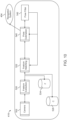
- FIG. 7 shows one example of implementing the sensor fusion module 430 using sensor data from the sensors 420.
- Any suitable sensor data from various sensors 420 may be used.
- the sensors 420 include an inertial measurement unit 470, a wheel encoder 472, and the vision system 402.
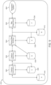
- FIG. 9 schematic representations of various data, data structures, and modules of the vision system in one example of an offline mode 414 for processing data are shown.
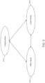
- the offline mode 414 may be used subsequent to a training mode 412 ( FIG . 5 ).
- the camera data 502 which may have been stored in data structure 510 as training images during a training mode, may be provided to feature extraction module 520.
- the feature extraction module 520 may utilize a feature extraction algorithm, a descriptor algorithm, or both to extract feature data that is provided to and stored in a data structure 528 based on results of the feature extraction or description algorithm.
- the artificial feature may be unpowered and, for example, may include a visible or non-visible pattern detectable by a camera. Some artificial features may be permanently placed.
- non-visible refers to emitting or reflecting wavelengths of light that are not visible to the human eye, but which may emit or reflect wavelengths visible by a camera, such as an infrared camera on the autonomous machine.
- the term "descriptor” refers to two-dimensional data that results from a descriptor algorithm.
- the descriptor describes the feature in the context of the image.
- a descriptor may describe pixel values, image gradients, scale-space information, or other data in the image near or around the feature.
- the descriptor may include an orientation vector for the feature or may include a patch of image. Any suitable descriptor algorithm for providing context for a feature in an image that is available to one having ordinary skill in the art may be used depending on the particular autonomous machine or application.
- a descriptor may be stored as part of feature data.
- the output of the feature extraction module 520 and/or the feature data stored in a data structure 528 may be provided to feature matching module 522.
- the feature matching module 522 may utilize a feature matching algorithm to match features identified in different training images. Different images may have different lighting around the same physical key points, which may lead to some differences in the descriptors for the same features. Features having a similarity above a threshold may be determined to be the same feature.
- Non-limiting examples of data that may be associated with each point in the 3DPC includes: one or more images, one or more descriptors, one or more poses, position uncertainty, and pose uncertainty for one or more poses.
- the 3DPC and associated data may be provided to and stored in a data structure 532.
- associated data may include one or more poses determined and associated with points in the 3DPC as pose data, which may describe the position and/or orientation of the platform or some other component of the system at the times when the features associated with the 3DPC were observed.
- pose data may describe the position and/or orientation of the platform or some other component of the system at the times when the features associated with the 3DPC were observed.
- positions and orientations of the autonomous machine during image recording may be determined based on the positions of various points in the 3DPC and positions of the corresponding features in the recorded images.
- Positions and orientations, or poses may also be determined directly during generation of the point cloud.
- the position, orientation, or both types of data represented in the poses may be used for boundary determination or pose correction by the navigation system.
- the output of the visual map building module 524 and/or the 3DPC and associated data stored in the data structure 532 may be provided to a map registration module 526.
- the non-vision-based data such as GPS data, IMU data, and odometry data, from the data structure 512 may also be provided to the map registration module 526.
- the map registration module 526 may determine and provide pose data based on a registered map, which may be provided to and used by the navigation system 404.
- pose data is provided from the map registration module 526 to the navigation system 404.
- the pose data may be estimated vision-based pose data.
- the registered map may also be provided to and stored in a data structure 534.
- the term "registered map” refers to a 3DPC that has been tied to a real-world scale, real-world orientation, or both.
- a registered map may be tied to a real-world map or frame of reference.
- a GPS may be used to tie the 3DPC to a real-world mapping service, such as GOOGLE MAPS TM .
- the 3DPC may generally be scaled from about 0.5 times up to about 2 times when registered to a real-world map or frame of reference. However, scaling is generally not limited to these ranges.
- real-world refers to the Earth or other existing frames of reference for a work region.
- a non-real-world frame of reference may be described as an arbitrary frame of reference.
- the operational images in the camera data 502 may be provided to the feature extraction module 520.
- the same or different algorithms to extract feature data from training images used during the offline mode 414 may be used on operational images in the online mode 416.
- the feature data from the feature extraction module 520 may be provided to the feature matching module 522.
- the feature matching module 522 may use the same or different algorithms used during the offline mode 414 to match feature data from feature extraction module 520 with features in registered map data from the data structure 534.
- feature data from the data structure 528 may also be used as an input to the feature matching module 522.
- the feature matching module 522 may match features using 2D correspondences, 3D correspondences, correspondences between 2D image positions and 2D projections of 3D data, descriptor values, or any combination of these.
- the matching data from the feature matching module 522 which may include 2D or 3D correspondences, may be provided to a pose estimation module 540.
- the pose data may be used by the feature matching module 522 to identify which features are likely to be seen in the camera data 502 based on the estimated pose of the autonomous machine and the locations at which these features are likely to be seen. This information may be used as an input into one or more algorithms of the feature matching module 522.
- the pose filter 542 may use information from an IMU, wheel encoder, or optical encoder (e.g., sensors 420 of FIGS. 6-7 ) to filter poses.
- the pose filter 542 may be described as using a pose based on non-vision-based sensors, such as an inertial-based navigation system (or INS) including an inertial measurement unit, to inform which poses may be filtered.
- the navigation system 404 of FIG. 6 may use an independent pose filter, for example, in the sensor fusion module 430.
- the resulting output, or pose data, from the different pose filters may be compared for correction of, or as a redundancy check on, either output.
- a series of timestamped images 550, 560, 570 and a 3DPC 580 are shown to illustrate one example of visual map building.
- a key point may be identified as a two-dimensional feature 552, 562, 572 in the respective image 550, 560, 570, for example, using a feature detector algorithm.
- Each feature 552, 562, 572 is extracted and a descriptor algorithm may be applied to generate a multi-dimensional descriptor 554, 564, 574 associated with the respective feature 552, 562, 572.
- the descriptors 554, 564, 574 are illustrated as circles around the respective feature 552, 562, 572.
- the features 552, 562, 572 and the descriptors 554, 564, 574 may be included in feature data.
- a map building technique may be applied to the feature data and the matching data to identify a three-dimensional point 582 in a 3DPC 580 that corresponds to the features 552, 562, 572. Each point of the 3DPC 580 may be determined in a similar manner.
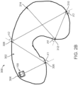
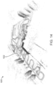
- a 3DPC 600 is shown with pose points 602.
- the pose points are drawn as red dots that appear to form a path, which is roughly outlined using a white dashed line for visibility.
- the path may be described as a path around a perimeter of the work region.
- Points corresponding to feature positions are drawn as black dots.
- pose points 602 may be determined along with the points corresponding to feature positions.
- Each pose point 602 corresponds to an estimated pose of the camera used to record one image.
- Each pose point 602 may be included in pose data provided to the navigation system, which may be used in boundary determination or pose correction.
- the boundary may be defined using a line or curve fit of the pose points 602.
- the boundary may also be defined relative to the line fit, curve fit, or the pose points 602.
- the boundary may be defined one foot outside of the line fit, curve fit, or the pose points 602.
- the quality of the 3DPC 600 may be evaluated.
- a quality level, or parameter, may also be assigned to various portions of the 3DPC 600.
- the quality level used to evaluate the 3DPC may be based on various parameters, such as at least one of: a number of poses reconstructed, a number of points reconstructed, reprojection error, point triangulation uncertainty, and reconstructed pose uncertainty.
- a 3DPC 610 is shown with pose points 612 and a low-quality portion 604 of the 3DPC.
- An autonomous machine may be directed along the path represented by the pose points 612.
- the path may be described as a path around a perimeter of the work region.
- One or more portions 604 of the 3DPC 600 may be identified as, or determined to be, a low-quality portion 604.
- a portion of the 3DPC may be determined to have a quality level below a quality threshold.
- the quality level may be based on, for example, uncertainty values associated with points, uncertainty in the poses corresponding to those points, or a low density of points.
- certain areas of the work region may have very few key points visible to the one or more cameras for identifying features (e.g., being near an open field) or the path may be so close to an obstacle such that key points just above or behind the obstacle are not visible from the path (e.g., being near a fence that obstructs the view of a tree beyond or above the fence due to a limited vertical field of view).
- identifying features e.g., being near an open field
- the path may be so close to an obstacle such that key points just above or behind the obstacle are not visible from the path (e.g., being near a fence that obstructs the view of a tree beyond or above the fence due to a limited vertical field of view).
- Coordinates or points associated with the low-quality portion may be provided to the navigation system.
- the navigation system may direct the autonomous machine to traverse the work region to record additional training images, for example, along a different, or secondary, path than the original desired boundary path that is likely to record additional images of key points that may be in the low-quality portion.
- the navigation system may direct the autonomous machine along the secondary path, for example, during a training mode or online mode.
- the autonomous machine may be directed to record images in an area of the work region associated with the low-quality portion of the 3DPC, which may be used to improve the quality of, or "fill in," this portion of the 3DPC.
- a 3DPC 620 is shown that represents the same work region as 3DPC 610 ( FIG. 13 ). However, the autonomous machine was directed along a path represented by pose points 622 to record images for generating the 3DPC 620. As illustrated, the 3DPC 622 does not include a low-quality portion.
- the path may be described as a secondary path.
- the secondary path may be defined within a boundary, or original path, represented by pose points 612 ( FIG. 13 ).
- the secondary path pay may be described as traversing along an interior of the work region.
- the secondary path may include more turns, or "zig-zag" paths, through the work region to capture more points of view from the one or more cameras on the autonomous machine.
- any type of changes may be made to the path, such as random, semi-random, or planned path changes, to determine the secondary path.
- a secondary path represented by pose points 622 is used for filling in the 3DPC 620, the original path represented by pose points 612 may still be used as the boundary that defines the work region.
- GPS data such as GPS-RTK data
- GPS-RTK data may be used to help navigate the autonomous machine through areas of the work region associated with low-quality portions of the 3DPC.
- GPS data may be provided to a sensor fusion module as one of the non-vision-based sensors.
- the autonomous machine may rely more on GPS data when the autonomous machine is traversing an area associated with low-quality portions of the 3DPC.
- the GPS data may be "weighted" more heavily than vision-based data.
- the GPS data may be used for pose correction or even as a primary non-vision-based sensor input to sensor fusion.
- the autonomous machine may "weight" vision-based data more heavily than GPS data, for example, when the autonomous machine is traversing an area of the work region that contains one or more obstacles that may hinder the GPS receiver 116 ( FIG. 1 ) from receiving appropriately timed signals from GPS satellites.
- the autonomous machine may also "weight" vision-based data more heavily, for example, when the autonomous machine is traversing an area of the work region that is not associated with low-quality portion of the 3DPC.
- FIG. 15 a flowchart of one example of a visual map building method used by the visual map building module 524 is shown.
- a 3DPC may be stored in the data structure 532.
- the visual map building method may employ removing extraneous points that may confuse various map building algorithms. For example, weak matches or points associated with high uncertainty values may be removed from data before certain map building algorithms are used to generate the 3DPC.
- a plurality of 6DOF poses and a plurality of boundary points determined based on the plurality of 6DOF poses may be stored in the data structure 532.
- a partial 3DPC may be initialized using data based on first and second training images at 652 (e.g., any pair of images).
- the partial 3DPC may be initialized using feature data corresponding to a first and a second training image.
- the feature data may include features and descriptors.
- the training images may be selected to be sufficiently spaced apart in the work region in distance or time, which may be considered a surrogate for distance as the autonomous machine traverses the work region.
- the training images may also be selected so that a sufficient number of features are visible in both images.
- a third training image with overlapping correspondence to the partial 3DPC is selected at 654.
- a third training image may be selected with overlapping correspondence with the partial 3DPC.
- the third training image may be selected to corroborate the points identified in the existing partial 3DPC based on the first two images.
- the overlapping correspondence may be evaluated to determine whether the third training image has a strong tie to the existing partial 3DPC.
- the third training image may be selected so that some number exceeding a threshold number of features are shared among the images and that the third training image is spaced some distance, time, or number of images away from the first and second training images by some threshold number.
- a camera pose may be determined under these same conditions.
- a pose of the camera used to take the third image may be estimated based on the partial 3DPC at 656.
- a new partial 3DPC may be determined based on feature data of the third training image and the partial 3DPC 658.
- positions of any new features relative to the partial 3DPC may be estimated using matching data associated with the third training image and matching data associated with the first and second training images.
- an additional unused training image with overlapping correspondence with the partial 3DPC may be selected at 654. Poses and positions for each of the additional training images may continue to be estimated at 656, 658.
- a graph optimizer may continue to be run on the estimated positions of features and unused training images at 660.
- the partial 3DPC may represent a full 3DPC.
- the visual map building method may end at 664 and store the 3DPC and pose data in the data structure 532.
- FIG. 16 a schematic representation of an autonomous machine navigation method 700 for training is shown.
- the autonomous machine may be directed along a work region, for example, along a desired boundary path of the work region at 702. While the autonomous machine is directed in training mode, training images may be captured by a vision system on the autonomous machine.
- the autonomous machine may be directed manually or automatically along the desired boundary path.
- the machine may also be directed along a path offset from the desired boundary path, for example, by a predefined distance.
- a 3DPC may be generated that represents the work region and/or an area beyond or surrounding the work region at 704.
- the 3DPC may also include points outside of the boundary of the work region or even outside of the work region (e.g., when the boundary is defined within the work region).
- the 3DPC may be generated based on feature data containing two-dimensional features extracted from training images.
- the 3DPC may also be generated based on matching data relating features in the feature data from different training images.
- Pose data may be generated and associated with points of the 3DPC that represents poses of the autonomous machine at 706.
- the pose data may be described as vision-based pose data.
- the pose data may include both position and orientation representing the position of the camera or autonomous machine during training mode.
- the pose data includes at least a three-dimensional position representing a pose of the autonomous machine during a training mode.
- the pose of a forward-facing camera may be used to estimate the position of the autonomous machine.
- a navigation system of the autonomous machine may be used to determine a boundary using non-vision-based sensor data and the pose data associated with the 3DPC at 708.
- the boundary may be used for subsequent navigation of the autonomous machine in the work region, for example, during an online mode.
- Non-vision-based sensor data may be obtained, for example, from an inertial measurement unit.
- the vision-based pose data associated with the 3DPC may be used to estimate or correct the boundary.
- a vision system of the autonomous machine may be used to determine vision-based pose data based on received operational images obtained and a 3DPC generated based on feature data extracted from training images at 804.
- the vision-based pose data may be determined independently of the non-vision-based sensor data.
- the vision-based pose data may be determined based at least in part on feedback from vision-based pose estimation or vison-based pose filtering.
- the navigation system may navigate the autonomous machine within a boundary of the work region based on the updated pose at 808.
- the navigation system may be used to provide propulsion commands to a propulsion system of the autonomous machine.
- training methods of the autonomous machine may include one, two, or more different phases.
- the machine may also, during training, transition to a different mode, such as an offline mode, between different phases of the training mode. Further, before beginning various phases of the training mode, the autonomous machine may perform a battery check before beginning, which may ensure that the machine is capable of performing the tasks needed during each phase.
- the training method 820 may also include an offline phase at 824, in which the autonomous machine generates a 3DPC, for example, in an offline mode while docked in a base station.
- the point cloud may be generated using the images and other sensor data recorded during the touring phase.
- the map generation phase at 828 may include generating a representation of one or more paths traversed by the autonomous machine during the mapping phase.
- the representation of the one or more paths may be a visual representation displayed to the user on a user interface device.
- a user interface device may be coupled to the autonomous machine for the touring phase or the mapping phase.
- a user interface device is a smartphone, which may be physically docked with or coupled to the autonomous machine in a position that is visible to the user or may be operably connected by wireless or wired connection to the autonomous machine for remote operation of the machine.
- the touring phase 822 may include recording a set of images during the tour at 838, for example, as the autonomous machine is directed along in the work region.
- the machine may be directed as instructed to the user.
- the recorded set of images may be processed to identify features.
- Non-vision-based sensor data such as wheel encoder data or IMU data, may also be recorded during the touring phase 822.
- the touring phase 822 may include touring the perimeter, touring the interior, or both touring the perimeter and the interior. Touring the interior may only be requested, for example, when the features identified in the images recorded during touring of the perimeter are insufficient to build a robust 3DPC for autonomous navigation.
- the perimeter and the interior may be toured regardless of the results of the perimeter touring.
- Sets of images for the perimeter and the interior may be recorded in the same session or in different sessions. For example, both sets of images may be recorded without an offline phase between them.
- Each set of images may include one or more images captured by the vision system of the autonomous machine.
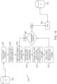
- FIG. 20 shows one specific example of a method 870 that may be used to carry out at least part of the method 820.
- the method 870 may include generating the 3DPC at 824, which may be performed after a touring phase.
- the 3DPC may be analyzed, and a determination may be made regarding whether the 3DPC includes any low-quality portions at 844. If the one or more low-quality portions are insufficient or unacceptable for navigation based on the 3DPC, the method 870 may include performing an autonomous or manual supplemental training run to improve feature-density in the low-quality portions identified.
- the method 870 may include generating a navigation map at 828, for example in an offline mode.
- the navigation map may define the one or more trained boundaries.
- the navigation map may be generated and stored separately from the 3DPC.
- the coordinate system of the navigation map may be localized to the coordinate system of the 3DPC, for example, when sensor fusion data is used to generate the boundaries.
- the navigation map may be generated as a 2D or 3D representation of the boundaries of the work region.
- the navigation map may be generated during the map generation phase of the training mode or during an offline mode.
- the navigation map may be displayed to the user, including the trained boundaries, via the user interface device.
- the trained boundaries may appear differently to the user than the visual representations of the paths due, for example, to localization or correction using the vision-based sensor data and the 3DPC.
- FIG. 21 shows one example of the handle assembly 90.
- a cradle 900 may be attached to the grip portion 902 of, and be part, of the handle assembly 90.
- the cradle 900 may be adapted to receive and hold the mobile device 119 (e.g., smartphone) in an orientation visible to the operator while standing or walking behind the housing (when the handle assembly is in the manual mode position).
- the mobile device 119 may support a communication protocol compatible with a radio 117 ( FIG. 1 ) of the mower 100 for reasons further described below.
- the mower 100 and cradle 900 may include provisions for a wired connection (e.g., serial, Universal Serial Bus, etc.) to the controller 120 ( FIG. 1 ) of the mower 100. Regardless of the control interface provided to the operator, he or she may control and manipulate the mower by interacting with controls associated with the handle assembly 90 (e.g., with virtual controls on the mobile device).
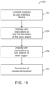
- the mower When the operator is ready to initiate the training mode, the mower may be pushed, using the handle assembly 90, to a perimeter of the work region (or to a perimeter of an exclusion zone). At this point, training may begin by selecting the appropriate training mode (e.g., a boundary training mode for the work region or an exclusion zone, or a transit zone training mode) presented on the display 166. In the case of the boundary training mode, the operator may then commence to traverse the boundary of the work region.
- the appropriate training mode e.g., a boundary training mode for the work region or an exclusion zone, or a transit zone training mode
- Such speed-related instructions/feedback may be presented textually or graphically to the operator.
- feedback and/or other status information may be presented as a quantitative speed indicator (e.g., speedometer), or a speed-related icon or object (e.g., an icon that changes color: green for acceptable speed, yellow or red for unacceptable speed).
- the display 908 could indicate whether a change in speed is needed by showing a speedometer reading alongside a desired target speed or showing "up" or “down” arrows to indicate a faster or slower speed is recommended.
- the display could provide a simplistic "pass/fail” indicator or provide audible indicators (via the mobile device 119 or the mower/controller) during or after the training mode.
- a method comprises the method according to embodiment A3, wherein generating the 3DPC further comprises:
- a method comprises the method according to any embodiment A3-A7, further comprising:
- a method comprises the method according to any embodiment A8-A9, further comprising determining whether a quality level of the 3DPC does not meet a quality threshold before recording the set of mapping images.
- a method comprises the method according to embodiment A16, further comprising performing a battery check before leaving the offline mode.
- a method comprises the method according to any preceding A embodiment, wherein:
- a method comprises the method according to any preceding A embodiment, wherein each pose represents one or both of a three-dimensional position and a three-dimensional orientation of the autonomous machine.
- a method comprises the method according to any preceding A embodiment, further comprising determining the one or more boundaries of the work region based on non-vision-based pose data and vision-based pose data for subsequent navigation of the autonomous machine in the work region.
- a method comprises the method according to any preceding A embodiment, wherein determining the current pose of the autonomous machine based on non-vision-based pose data is repeated at a first rate and updating the current pose based on the vision-based pose data is repeated at a second rate slower than the first rate.
- a method comprises the method according to any preceding A embodiment, wherein non-vision-based pose data comprises one or both of an inertial measurement data and wheel encoding data.
- a method comprises the method according to any embodiment A2-A24, further comprising associating points in the 3DPC with at least one of: one or more images, one or more descriptors, one or more poses, position uncertainty, and pose uncertainty for one or more poses.
- a method comprises the method according to any embodiment A2-A25, wherein the feature data comprises a two-dimensional position and a multi-dimensional descriptor.
- a method comprises the method according to any preceding A embodiment, wherein determining vision-based pose data is based at least in part on feedback from vision-based pose estimation or vision-based pose filtering.
- a method comprises the method according to embodiment B 1, wherein directing the autonomous machine during the mapping phase of the training mode along one or more paths comprises:
- a method comprises the method according to embodiment B2, wherein displaying the status of the mapping phase occurs during traversal of the boundary of the work region.
- a method comprises the method according to any embodiment B2-B3, wherein determining whether the at least one boundary satisfies a path criterion comprises determining whether the at least one boundary defines a bounded area.
- a method comprises the method according to any preceding B embodiment, further comprising:
- a method comprises the method according to embodiment B5, further comprising:
- a method comprises the method according to any preceding B embodiment, further comprising:
- a method comprises the method according to embodiment B7, further comprising deploying one or more artificial features along the one or more areas of the work region associated with one or more low-quality portions of the 3DPC before directing the autonomous machine to record the new set of touring images.
- a method comprises the method according to any preceding B embodiment, further comprising displaying a representation of the one or more paths to a user before defining the one or more boundaries in the navigational map.
- a method comprises the method according to embodiment B9, wherein the representation associated with each path is based on an outer perimeter of the respective path.
- a method comprises the method according to any preceding B embodiment, further comprising displaying instructions to a user to manually direct the autonomous machine along the perimeter, the interior, or both of the work region for the touring phase or the mapping phase of the training mode.
- a method comprises the method according to any preceding B embodiment, wherein the one or more boundaries are used to define one or more of a perimeter of the work region, a containment zone in the work region, an exclusion zone in the work region, or a transit zone in the work region.
- an autonomous machine is adapted to carry out a method according to any A or B embodiment.
- a machine comprises the machine according to embodiment C2, wherein the propulsion controller is adapted to control speed and rotational direction of the wheels independently, thereby controlling both speed and direction of the housing over the ground surface.
- a method comprises the method according to embodiment D1, wherein determining the boundary is based on non-vision-based sensor data and pose data.
- an autonomous machine comprises:
- a machine comprises the machine according to embodiment F1, wherein the propulsion controller is configured to control speed and rotational direction of each wheel of the set of wheels independently, thereby controlling both speed and direction of the housing over the ground surface.
- references to "one embodiment,” “an embodiment,” “certain embodiments,” or “some embodiments,” etc. means that a particular feature, configuration, composition, or characteristic described in connection with the embodiment is included in at least one embodiment of the disclosure. Thus, the appearances of such phrases in various places throughout are not necessarily referring to the same embodiment of the disclosure. Furthermore, the particular features, configurations, compositions, or characteristics may be combined in any suitable manner in one or more embodiments.
Landscapes
- Engineering & Computer Science (AREA)
- Physics & Mathematics (AREA)
- Radar, Positioning & Navigation (AREA)
- Remote Sensing (AREA)
- General Physics & Mathematics (AREA)
- Automation & Control Theory (AREA)
- Aviation & Aerospace Engineering (AREA)
- Theoretical Computer Science (AREA)
- Multimedia (AREA)
- Computer Vision & Pattern Recognition (AREA)
- Life Sciences & Earth Sciences (AREA)
- Environmental Sciences (AREA)
- Evolutionary Computation (AREA)
- Artificial Intelligence (AREA)
- Health & Medical Sciences (AREA)
- Medical Informatics (AREA)
- Software Systems (AREA)
- Computing Systems (AREA)
- General Health & Medical Sciences (AREA)
- Electromagnetism (AREA)
- Geometry (AREA)
- Databases & Information Systems (AREA)
- Business, Economics & Management (AREA)
- Game Theory and Decision Science (AREA)
- Data Mining & Analysis (AREA)
- Computational Linguistics (AREA)
- Biophysics (AREA)
- Molecular Biology (AREA)
- Biomedical Technology (AREA)
- General Engineering & Computer Science (AREA)
- Mathematical Physics (AREA)
- Harvester Elements (AREA)
- Control Of Position, Course, Altitude, Or Attitude Of Moving Bodies (AREA)
- Guiding Agricultural Machines (AREA)
- Navigation (AREA)
Applications Claiming Priority (6)
| Application Number | Priority Date | Filing Date | Title |
|---|---|---|---|
| US201862716208P | 2018-08-08 | 2018-08-08 | |
| US201862716716P | 2018-08-09 | 2018-08-09 | |
| US201862741988P | 2018-10-05 | 2018-10-05 | |
| US201962818893P | 2019-03-15 | 2019-03-15 | |
| PCT/US2019/045443 WO2020033504A2 (en) | 2018-08-08 | 2019-08-07 | Autonomous machine navigation and training using vision system |
| EP19755504.8A EP3833176B1 (de) | 2018-08-08 | 2019-08-07 | Autonome maschinennavigation und training mit sichtsystem |
Related Parent Applications (2)
| Application Number | Title | Priority Date | Filing Date |
|---|---|---|---|
| EP19755504.8A Division EP3833176B1 (de) | 2018-08-08 | 2019-08-07 | Autonome maschinennavigation und training mit sichtsystem |
| EP19755504.8A Division-Into EP3833176B1 (de) | 2018-08-08 | 2019-08-07 | Autonome maschinennavigation und training mit sichtsystem |
Publications (2)
| Publication Number | Publication Date |
|---|---|
| EP4397167A2 true EP4397167A2 (de) | 2024-07-10 |
| EP4397167A3 EP4397167A3 (de) | 2024-09-25 |
Family
ID=67660495
Family Applications (5)
| Application Number | Title | Priority Date | Filing Date |
|---|---|---|---|
| EP24170502.9A Pending EP4397167A3 (de) | 2018-08-08 | 2019-08-07 | Autonome maschinennavigation und training mit sichtsystem |
| EP19755504.8A Active EP3833176B1 (de) | 2018-08-08 | 2019-08-07 | Autonome maschinennavigation und training mit sichtsystem |
| EP22178944.9A Active EP4079135B1 (de) | 2018-08-08 | 2019-08-07 | Verfahren zum trainieren eines autonomen fahrzeugs |
| EP25166599.8A Pending EP4571253A3 (de) | 2018-08-08 | 2019-08-07 | Verfahren zum trainieren eines autonomen fahrzeugs |
| EP19755761.4A Active EP3833177B1 (de) | 2018-08-08 | 2019-08-07 | Griff und verfahren zum trainieren eines autonomen fahrzeugs und verfahren zu dessen aufbewahrung |
Family Applications After (4)
| Application Number | Title | Priority Date | Filing Date |
|---|---|---|---|
| EP19755504.8A Active EP3833176B1 (de) | 2018-08-08 | 2019-08-07 | Autonome maschinennavigation und training mit sichtsystem |
| EP22178944.9A Active EP4079135B1 (de) | 2018-08-08 | 2019-08-07 | Verfahren zum trainieren eines autonomen fahrzeugs |
| EP25166599.8A Pending EP4571253A3 (de) | 2018-08-08 | 2019-08-07 | Verfahren zum trainieren eines autonomen fahrzeugs |
| EP19755761.4A Active EP3833177B1 (de) | 2018-08-08 | 2019-08-07 | Griff und verfahren zum trainieren eines autonomen fahrzeugs und verfahren zu dessen aufbewahrung |
Country Status (7)
| Country | Link |
|---|---|
| US (3) | US11334082B2 (de) |
| EP (5) | EP4397167A3 (de) |
| CN (3) | CN115826585B (de) |
| AU (3) | AU2019317453B2 (de) |
| CA (2) | CA3106284A1 (de) |
| ES (1) | ES2983425T3 (de) |
| WO (2) | WO2020033504A2 (de) |
Families Citing this family (82)
| Publication number | Priority date | Publication date | Assignee | Title |
|---|---|---|---|---|
| CN111479662B (zh) * | 2017-10-25 | 2023-07-07 | Lg电子株式会社 | 学习障碍物的人工智能移动机器人及其控制方法 |
| WO2019183277A1 (en) * | 2018-03-20 | 2019-09-26 | Nant Holdings Ip, Llc | Volumetric descriptors |
| CN108717710B (zh) * | 2018-05-18 | 2022-04-22 | 京东方科技集团股份有限公司 | 室内环境下的定位方法、装置及系统 |
| EP4218390A1 (de) | 2018-05-25 | 2023-08-02 | The Toro Company | Autonome bodenpflegemaschinen mit wegplanung für fallen- und hindernisvermeidung |
| EP4008170A1 (de) | 2018-05-25 | 2022-06-08 | The Toro Company | Systeme und verfahren zum betrieb einer robotermaschine in einem autonomen modus und einem manuellen modus |
| EP4397167A3 (de) | 2018-08-08 | 2024-09-25 | The Toro Company | Autonome maschinennavigation und training mit sichtsystem |
| US12185662B2 (en) * | 2018-11-20 | 2025-01-07 | Honda Motor Co., Ltd. | Control apparatus of autonomously navigating work machine |
| US12593747B2 (en) | 2019-03-25 | 2026-04-07 | The Toro Company | Autonomous working machine with computer vision-based monitoring and security system |
| JP7222775B2 (ja) * | 2019-03-26 | 2023-02-15 | 日立建機株式会社 | 作業機械 |
| CA3232590A1 (en) * | 2019-04-05 | 2020-10-08 | Equipmentshare.Com Inc. | System and method for autonomous operation of a machine |
| WO2020214925A1 (en) | 2019-04-17 | 2020-10-22 | The Toro Company | Autonomous machine navigation and charging |
| JP7376264B2 (ja) * | 2019-07-01 | 2023-11-08 | 株式会社小松製作所 | 作業機械を含むシステム、および作業機械 |
| US12433179B2 (en) | 2019-08-06 | 2025-10-07 | The Toro Company | Vehicle with detection system for detecting ground surface and sub-surface objects, and method for controlling vehicle |
| WO2021037116A1 (zh) * | 2019-08-27 | 2021-03-04 | 南京德朔实业有限公司 | 自行走割草系统及其漏割区域的补充作业的方法 |
| KR102877692B1 (ko) * | 2019-09-04 | 2025-10-30 | 엘지전자 주식회사 | 이동 로봇 및 그의 구동 방법 |
| IT201900016934A1 (it) * | 2019-09-23 | 2021-03-23 | Fabrizio Bernini | Robot tagliaerba |
| US20210173410A1 (en) * | 2019-12-05 | 2021-06-10 | Cnh Industrial America Llc | System and method for controlling the direction of travel of a work vehicle based on an adjusted field map |
| SE544287C2 (en) * | 2019-12-06 | 2022-03-29 | Husqvarna Ab | Robotic work tool system and method for defining a working area perimeter |
| TWI842024B (zh) * | 2019-12-20 | 2024-05-11 | 美商尼安蒂克公司 | 合併來自地圖建立裝置之局部地圖 |
| CN113068501A (zh) * | 2020-01-06 | 2021-07-06 | 苏州宝时得电动工具有限公司 | 一种智能割草机 |
| CN111352420B (zh) * | 2020-03-03 | 2021-08-10 | 厦门大学 | 一种激光导航agv高精度定位及目标对准控制方法 |
| SE544024C2 (en) * | 2020-03-03 | 2021-11-09 | Husqvarna Ab | Robotic work tool system and method for redefining a work area perimeter |
| US11789458B2 (en) * | 2020-03-06 | 2023-10-17 | Catepillar Paving Products, Inc. | Automatic mode resume system for a mobile machine |
| SE544298C2 (en) * | 2020-04-14 | 2022-03-29 | Husqvarna Ab | Robotic work tool system and method for defining a working area |
| EP4398202B1 (de) | 2020-07-02 | 2026-04-01 | The Toro Company | Eine autonome bodenreinigungsmaschine mit einem bildsystem zur navigation und ein verfahren zur autonomen maschinennavigation |
| WO2022010684A1 (en) * | 2020-07-09 | 2022-01-13 | The Toro Company | Autonomous machine navigation using reflections from subsurface objects |
| US20220039313A1 (en) * | 2020-08-05 | 2022-02-10 | Scythe Robotics, Inc. | Autonomous lawn mower |
| US11579618B2 (en) * | 2020-09-18 | 2023-02-14 | Scythe Robotics, Inc. | Coverage planner |
| US11992961B2 (en) * | 2020-11-17 | 2024-05-28 | Ubtech Robotics Corp Ltd | Pose determination method, robot using the same, and computer readable storage medium |
| US12399501B2 (en) * | 2020-12-10 | 2025-08-26 | AI Incorporated | Method of lightweight simultaneous localization and mapping performed on a real-time computing and battery operated wheeled device |
| WO2022143506A1 (zh) * | 2020-12-30 | 2022-07-07 | 格力博(江苏)股份有限公司 | 智能割草机及其控制方法、系统和存储介质 |
| CN112833890B (zh) * | 2020-12-30 | 2024-08-13 | 深圳市海柔创新科技有限公司 | 地图构建方法、装置、设备、机器人及存储介质 |
| US12296694B2 (en) | 2021-03-10 | 2025-05-13 | Techtronic Cordless Gp | Lawnmowers |
| IT202100009023A1 (it) * | 2021-04-09 | 2022-10-09 | Stiga S P A In Breve Anche St S P A | Sistema di manutenzione di terreni, in particolare configurato per attivare una modalità di risparmio energetico di un dispositivo mobile previa comparazione tra livelli di carica |
| EP4332931A4 (de) * | 2021-04-27 | 2025-06-11 | Kubota Corporation | Überwachungssystem für arbeitsmaschinen |
| WO2021178980A1 (en) * | 2021-04-28 | 2021-09-10 | Innopeak Technology, Inc | Data synchronization and pose prediction in extended reality |
| EP4579193A3 (de) * | 2021-06-17 | 2025-07-30 | The Toro Company | Autonomes arbeitsfahrzeug mit bildbasierter lokalisierung |
| WO2022272151A1 (en) * | 2021-06-24 | 2022-12-29 | Mtd Products Inc | Foldable handles for high-efficiency turf maintenance tool |
| CN115669357A (zh) * | 2021-07-29 | 2023-02-03 | 南京泉峰科技有限公司 | 行走式作业设备与手推式草坪护理车 |
| US12111391B1 (en) * | 2021-07-30 | 2024-10-08 | Geophysical Survey Systems, Inc. | Positional accuracy using ground penetrating radar |
| CN113885495B (zh) * | 2021-09-29 | 2024-08-20 | 上海菲蒽蔓机器人科技有限公司 | 一种基于机器视觉的室外自动工作控制系统、方法及设备 |
| SE2151264A1 (en) * | 2021-10-15 | 2023-04-16 | Husqvarna Ab | Robotic lawn mower |
| WO2023071798A1 (zh) * | 2021-11-01 | 2023-05-04 | 南京泉峰科技有限公司 | 后走式动力工具 |
| US20240008399A1 (en) * | 2021-11-01 | 2024-01-11 | Nanjing Chervon Industry Co., Ltd. | Walk-behind working machine |
| US12443180B2 (en) | 2021-11-10 | 2025-10-14 | Techtronic Cordless Gp | Robotic lawn mowers |
| US12129607B2 (en) * | 2021-11-24 | 2024-10-29 | Caterpillar Paving Products Inc. | Control system and method for defining and generating compactor work area |
| US20230194301A1 (en) * | 2021-12-16 | 2023-06-22 | Univrses Ab | High fidelity anchor points for real-time mapping with mobile devices |
| AU2023200381A1 (en) | 2022-01-31 | 2023-08-17 | Techtronic Cordless Gp | Robotic garden tool |
| US12520752B2 (en) * | 2022-02-01 | 2026-01-13 | Honda Motor Co., Ltd. | Lawn mower and machine apparatus and method with storage features |
| WO2023150032A1 (en) | 2022-02-02 | 2023-08-10 | The Toro Company | Autonomous working vehicle system having base station with canopy |
| EP4476598A2 (de) * | 2022-02-07 | 2024-12-18 | Doosan Bobcat North America, Inc. | Wegbestimmung für automatische mäher |
| TWI808669B (zh) * | 2022-03-04 | 2023-07-11 | 國眾電腦股份有限公司 | 多點同步指導偕同作業系統及其方法 |
| US12543638B2 (en) | 2022-03-24 | 2026-02-10 | Willand (Beijing) Technology Co., Ltd. | Method for determining information, remote terminal, and mower |
| EP4270138A1 (de) | 2022-04-28 | 2023-11-01 | Techtronic Cordless GP | Erzeugung einer virtuellen grenze für ein robotisches gartenwerkzeug |
| SE547186C2 (en) * | 2022-05-06 | 2025-05-20 | Husqvarna Ab | Lawnmower system comprising a robotic lawnmower and a detachable sensor module |
| US12472611B2 (en) | 2022-05-31 | 2025-11-18 | Techtronic Cordless Gp | Peg driver |
| CN115167418B (zh) * | 2022-07-04 | 2023-06-27 | 未岚大陆(北京)科技有限公司 | 转移路径生成方法、装置、电子设备和计算机存储介质 |
| CN115171237A (zh) * | 2022-07-12 | 2022-10-11 | 国网河北省电力有限公司超高压分公司 | 一种3d成像巡视记录仪 |
| EP4310621B1 (de) | 2022-07-19 | 2025-02-12 | Techtronic Cordless GP | Anzeige zur steuerung eines robotischen werkzeugs |
| AU2023206123A1 (en) | 2022-07-29 | 2024-02-15 | Techtronic Cordless Gp | Generation of a cryptography key for a robotic garden tool |
| US12541199B2 (en) * | 2022-08-16 | 2026-02-03 | Kubota Corporation | Autonomous operating zone setup for a working vehicle or other working machine |
| US20240081180A1 (en) * | 2022-09-14 | 2024-03-14 | Mtd Products Inc | Compact folding handles and electronic control system for high-efficiency turf maintenance tool |
| EP4593578A1 (de) | 2022-09-29 | 2025-08-06 | The Toro Company | Rasenmäher mit grasleitsystem |
| EP4633354A2 (de) | 2022-12-13 | 2025-10-22 | The Toro Company | Autonomes bodenarbeitsfahrzeugsystem und fahrzeugreinigungssystem zur verwendung damit |
| US11678604B1 (en) | 2022-12-21 | 2023-06-20 | Sensori Robotics, LLC | Smart lawnmower with development of mowing policy and system and method for use of same |
| US12001182B1 (en) * | 2022-12-21 | 2024-06-04 | Sensori Robotics, LLC | Smart lawnmower with realization of mowing policy and system and method for use of same |
| US12547129B2 (en) | 2022-12-21 | 2026-02-10 | Sensori Robotics, LLC | Smart lawnmower with development of mowing policy and system and method for use of same |
| IT202300001740A1 (it) | 2023-02-02 | 2024-08-02 | Stiga S P A In Breve Anche St S P A | Accessorio ed assieme tra tale accessorio ed un dispositivo mobile |
| AU2024221405A1 (en) * | 2023-02-17 | 2025-08-07 | The Toro Company | Image notification for autonomous grounds maintenance machines |
| US12429875B2 (en) | 2023-04-25 | 2025-09-30 | Textron Innovations Inc. | Providing autonomous mower control via geofencing |
| CN121038932A (zh) * | 2023-05-01 | 2025-11-28 | 宝时得科技(中国)有限公司 | 一种控制方法、存储介质及自主工作机器 |
| CN116399330B (zh) * | 2023-05-29 | 2023-08-15 | 未岚大陆(北京)科技有限公司 | 地图修改方法、装置、电子设备和存储介质 |
| WO2025019467A1 (en) | 2023-07-18 | 2025-01-23 | The Toro Company | Ground care machine platform with autonomously controllable features |
| DE102023208373A1 (de) * | 2023-08-31 | 2025-03-06 | Robert Bosch Gesellschaft mit beschränkter Haftung | Verfahren zum Bestimmen einer Umrandung eines Arbeitsbereiches für ein mobiles Gerät |
| DE102023208377A1 (de) * | 2023-08-31 | 2025-03-06 | Robert Bosch Gesellschaft mit beschränkter Haftung | Verfahren zum Bestimmen einer zusätzlichen Umrandung eines Arbeitsbereiches für ein mobiles Gerät |
| KR20250097437A (ko) * | 2023-12-21 | 2025-06-30 | 삼성전자주식회사 | 경로 생성 방법 및 장치 |
| WO2025151265A1 (en) | 2024-01-09 | 2025-07-17 | The Toro Company | Anti-theft system for autonomous work vehicle |
| WO2025175193A1 (en) | 2024-02-14 | 2025-08-21 | The Toro Company | Control system for turf roller |
| CN117863190B (zh) * | 2024-03-08 | 2024-07-19 | 广州小鹏汽车科技有限公司 | 足式机器人的移动控制方法及足式机器人 |
| CN121713756A (zh) * | 2024-09-24 | 2026-03-24 | 苏州宝时得电动工具有限公司 | 一种园艺机器人的控制方法和园艺机器人 |
| JP2026059945A (ja) * | 2024-09-27 | 2026-04-08 | 株式会社やまびこ | 作業機 |
| CN120779797B (zh) * | 2025-05-27 | 2026-02-06 | 浙江拓步智能科技有限公司 | 一种基于磁感分析的室外自动工具控制方法及系统 |
Family Cites Families (136)
| Publication number | Priority date | Publication date | Assignee | Title |
|---|---|---|---|---|
| US2727753A (en) * | 1952-12-08 | 1955-12-20 | Foley Mfg Company | Adjustable lawn mower handle |
| US3357716A (en) * | 1965-01-18 | 1967-12-12 | M T & D Company | Handle construction |
| US3855763A (en) * | 1972-09-15 | 1974-12-24 | R Dunton | Self-propelled rotary lawn mower |
| US5209051A (en) * | 1991-03-08 | 1993-05-11 | Langdon Christopher D | Lawn mowers including push handles |
| JP3019520B2 (ja) | 1991-09-03 | 2000-03-13 | 松下電器産業株式会社 | 自走式掃除機 |
| US5261215A (en) * | 1992-07-24 | 1993-11-16 | Ryobi Motor Products Corp. | Vertically storable lawn mower |
| GB2277152A (en) | 1993-04-03 | 1994-10-19 | Cat Systems Ltd | Localising system for robotic vehicles |
| US5394965A (en) | 1993-09-17 | 1995-03-07 | Kho; Dick T. | Attachable pull handle for suitcases |
| US5606851A (en) | 1993-09-22 | 1997-03-04 | Briggs & Stratton Corporation | Battery-powered lawn cutting system |
| US6301746B1 (en) | 1998-01-09 | 2001-10-16 | Andiamo, Inc. | Telescoping handle assembly for luggage and other luggable items |
| US6339735B1 (en) | 1998-12-29 | 2002-01-15 | Friendly Robotics Ltd. | Method for operating a robot |
| US6158089A (en) * | 1999-03-10 | 2000-12-12 | Thomas Monahan Company | Telescoping handle |
| JP2002181560A (ja) | 2000-12-08 | 2002-06-26 | Matsushita Electric Ind Co Ltd | ポリゴン情報伝達方法とそれを実施する装置 |
| US7097181B2 (en) | 2001-11-02 | 2006-08-29 | Outrigger, Inc. | Angular handle assembly for wheeled luggage |
| US20030144774A1 (en) * | 2002-01-29 | 2003-07-31 | Trissel Ronald L. | Kit and method for converting conventional lawnmower to a robotic lawnmower |
| US7054716B2 (en) | 2002-09-06 | 2006-05-30 | Royal Appliance Mfg. Co. | Sentry robot system |
| US20050273967A1 (en) | 2004-03-11 | 2005-12-15 | Taylor Charles E | Robot vacuum with boundary cones |
| WO2006002385A1 (en) | 2004-06-24 | 2006-01-05 | Irobot Corporation | Programming and diagnostic tool for a mobile robot |
| US10705533B1 (en) * | 2005-05-31 | 2020-07-07 | Richard Anthony Bishel | Autonomous lawnmower |
| ES2707155T3 (es) | 2006-03-17 | 2019-04-02 | Irobot Corp | Confinamiento de robot |
| EP1943894B1 (de) | 2007-01-15 | 2010-05-19 | Kanzaki Kokyukoki Mfg. Co., Ltd. | Rasenmäher |
| DE102007027648A1 (de) | 2007-06-15 | 2008-12-18 | Robert Bosch Gmbh | Lokalisierungssystem für ein Roboterfahrzeug |
| DE102007060056A1 (de) | 2007-12-13 | 2009-06-18 | Robert Bosch Gmbh | Ansteuersystem und Ansteuerverfahren für ein Roboterfahrzeug sowie Roboterfahrzeug |
| DE102009028598A1 (de) * | 2009-08-17 | 2011-03-03 | Robert Bosch Gmbh | Autonome mobile Plattform zur Oberflächenbearbeitung |
| US8224516B2 (en) | 2009-12-17 | 2012-07-17 | Deere & Company | System and method for area coverage using sector decomposition |
| WO2011115534A1 (en) | 2010-03-17 | 2011-09-22 | Husqvarna Ab | Method and system for navigating a robotic garden tool |
| CN102273354A (zh) * | 2010-06-09 | 2011-12-14 | 泉峰(中国)贸易有限公司 | 草坪维护设备 |
| US8776337B2 (en) | 2010-07-30 | 2014-07-15 | Hewlett-Packard Development Company, L.P. | Methods of forming capacitive sensors |
| WO2013002773A1 (en) * | 2011-06-29 | 2013-01-03 | Husqvarna Consumer Outdoor Products N.A., Inc. | Lawn care vehicle adjustable steering assembly |
| US9462747B2 (en) * | 2011-11-03 | 2016-10-11 | Brigs & Stratton Corporation | Vertically storable engine and mower |
| EP2620050B1 (de) | 2012-01-25 | 2016-07-27 | Honda Research Institute Europe GmbH | System, Verfahren und Vorrichtung zur unbeaufsichtigten Anpassung der Wahrnehmung eines automatischen Mähers |
| US9241441B2 (en) | 2012-02-22 | 2016-01-26 | Husqvarna Ab | Robotic lawnmower |
| CN102523817B (zh) * | 2012-02-22 | 2014-03-12 | 南京德朔实业有限公司 | 多档位把手机构及包含该把手机构的割草机 |
| US11282287B2 (en) | 2012-02-24 | 2022-03-22 | Matterport, Inc. | Employing three-dimensional (3D) data predicted from two-dimensional (2D) images using neural networks for 3D modeling applications and other applications |
| US9324190B2 (en) | 2012-02-24 | 2016-04-26 | Matterport, Inc. | Capturing and aligning three-dimensional scenes |
| DE202012101866U1 (de) | 2012-05-22 | 2012-07-02 | Macauto Industrial Co., Ltd. | Roboterrasenmäher, der in einem Handschiebemodus betrieben werden kann |
| US9475196B2 (en) | 2012-06-26 | 2016-10-25 | Husqvarna Ab | Detachable user interface for a robotic vehicle |
| WO2014008627A1 (en) | 2012-07-09 | 2014-01-16 | Techtronic Outdoor Products Technology Limited | An interface for a power tool |
| PT106442A (pt) * | 2012-07-13 | 2014-01-13 | Handgo Unipessoal Lda | Cesto com rodas aperfeiçoado |
| GB2506338A (en) * | 2012-07-30 | 2014-04-02 | Sony Comp Entertainment Europe | A method of localisation and mapping |
| EP2885683A4 (de) | 2012-08-14 | 2016-06-01 | Husqvarna Ab | Grenzdefinitionssystem für ein roboterfahrzeug |
| WO2014027945A1 (en) | 2012-08-14 | 2014-02-20 | Husqvarna Ab | Mower with object detection system |
| US9383753B1 (en) * | 2012-09-26 | 2016-07-05 | Google Inc. | Wide-view LIDAR with areas of special attention |
| EP2906032B1 (de) | 2012-10-09 | 2022-06-22 | Husqvarna AB | System zur verbesserung der reichweitenverteilung eines robotischen gartenwerkzeugs |
| US9888627B2 (en) * | 2012-10-15 | 2018-02-13 | Chervon (Hk) Limited | Lawncare apparatus with a foldable operating arm |
| US9241442B2 (en) | 2012-10-23 | 2016-01-26 | Daniel A. DIAZDELCASTILLO | Autonomous and remote control all purpose machine (ARCAPM) |
| JP6240384B2 (ja) * | 2012-11-29 | 2017-11-29 | ヤンマー株式会社 | 自律走行作業システム |
| US10149430B2 (en) | 2013-02-20 | 2018-12-11 | Husqvarna Ab | Robotic work tool configured for improved turning in a slope, a robotic work tool system, and a method for use in the robot work tool |
| EP2959348B1 (de) | 2013-02-20 | 2018-09-19 | Husqvarna AB | Robotisches arbeitswerkzeugsystem und -verfahren mit einer ladestation |
| FR3002826B1 (fr) | 2013-03-08 | 2015-03-27 | Castorama France | Tondeuse a gazon |
| PL2774470T3 (pl) * | 2013-03-08 | 2019-11-29 | Castorama France | Kosiarka do trawy |
| US9754165B2 (en) * | 2013-07-30 | 2017-09-05 | The Boeing Company | Automated graph local constellation (GLC) method of correspondence search for registration of 2-D and 3-D data |
| GB201313541D0 (en) * | 2013-07-30 | 2013-09-11 | Digital Line Markers Fze | User-propelled collapsible apparatus |
| CN205922034U (zh) | 2013-09-19 | 2017-02-08 | 日立工机株式会社 | 自行式割草机 |
| CN203872585U (zh) | 2013-10-10 | 2014-10-15 | 南京德朔实业有限公司 | 割草机及其控制电路 |
| US9573275B2 (en) | 2013-11-12 | 2017-02-21 | Husqvarna Ab | Navigation for a robotic working tool |
| WO2015072896A1 (en) | 2013-11-12 | 2015-05-21 | Husqvarna Ab | Improved navigation for a robotic working tool |
| EP2884364B1 (de) | 2013-12-12 | 2018-09-26 | Hexagon Technology Center GmbH | Autonomes Gartenarbeitsfahrzeug mit Kamera |
| EP3084541B1 (de) | 2013-12-19 | 2019-05-08 | Husqvarna AB | Navigation für ein robotisches arbeitswerkzeug |
| US10185325B2 (en) | 2013-12-19 | 2019-01-22 | Husqvarna Ab | Obstacle detection for a robotic working tool |
| EP3084542B1 (de) | 2013-12-19 | 2019-07-24 | Husqvarna AB | System und verfahren zur navigation eines robotischen arbeitswerkzeugs |
| EP3682725A1 (de) * | 2014-01-21 | 2020-07-22 | Positec Power Tools (Suzhou) Co., Ltd | Automatischer rasenmäher |
| TWM547502U (zh) | 2017-03-14 | 2017-08-21 | Mace Group Inc | 自行車手機支架結構 |
| WO2015153109A1 (en) | 2014-03-31 | 2015-10-08 | Irobot Corporation | Autonomous mobile robot |
| EP3657292B1 (de) | 2014-05-15 | 2021-06-16 | Husqvarna Ab | Automatische empfindlichkeitseinstellung in einem objekterkennungssystem |
| JP6688747B2 (ja) | 2014-06-19 | 2020-04-28 | ハスクバーナ・アーベー | 自動的なビーコン位置判定 |
| EP3158409B1 (de) | 2014-06-19 | 2021-01-20 | Husqvarna Ab | Gartenvisualisierung und -kartierung über ein roboterfahrzeug |
| JP5792361B1 (ja) | 2014-06-25 | 2015-10-07 | シャープ株式会社 | 自律移動装置 |
| EP3161571B1 (de) | 2014-06-30 | 2020-03-04 | Husqvarna AB | Verbessertes robotisches arbeitswerkzeug |
| JP6131385B2 (ja) * | 2014-07-30 | 2017-05-17 | ヤンマー株式会社 | 遠隔操作装置 |
| US9516806B2 (en) | 2014-10-10 | 2016-12-13 | Irobot Corporation | Robotic lawn mowing boundary determination |
| GB201419883D0 (en) * | 2014-11-07 | 2014-12-24 | F Robotics Acquisitions Ltd | Domestic robotic system and method |
| WO2016083870A1 (en) | 2014-11-26 | 2016-06-02 | Husqvarna Ab | Remote interaction with a robotic vehicle |
| WO2016091312A1 (en) | 2014-12-11 | 2016-06-16 | Husqvarna Ab | Improved navigation for a robotic working tool |
| US9420741B2 (en) * | 2014-12-15 | 2016-08-23 | Irobot Corporation | Robot lawnmower mapping |
| EP3971672A1 (de) | 2014-12-17 | 2022-03-23 | Husqvarna AB | Autonomes robotisches fahrzeug mit mehreren sensoren und kartierungsfähigkeit |
| EP3232763A1 (de) | 2014-12-17 | 2017-10-25 | Husqvarna AB | Roboterfahrzeug mit automatischer kamerakalibrierung |
| EP3234718B1 (de) | 2014-12-17 | 2018-10-24 | Husqvarna AB | Bewegungsgrenzenlernendes roboterfahrzeug |
| EP3234722A2 (de) | 2014-12-17 | 2017-10-25 | Husqvarna AB | Autonomes robotisches fahrzeug mit mehreren sensoren mit rasenpflegefunktion |
| WO2016097896A1 (en) | 2014-12-18 | 2016-06-23 | Husqvarna Ab | Parcel mapping via electrical resistance detection of a robotic vehicle |
| WO2016097891A1 (en) | 2014-12-18 | 2016-06-23 | Husqvarna Ab | Robotic vehicle for detecting gps shadow zones |
| US9538702B2 (en) | 2014-12-22 | 2017-01-10 | Irobot Corporation | Robotic mowing of separated lawn areas |
| WO2016103070A1 (en) | 2014-12-22 | 2016-06-30 | Husqvarna Ab | Area exclusion for operation of a robotic vehicle |
| EP4235596A3 (de) * | 2014-12-22 | 2023-10-04 | Husqvarna AB | Grasstrukturdetektion durch ein robotisches fahrzeug |
| WO2016103067A1 (en) | 2014-12-22 | 2016-06-30 | Husqvarna Ab | Garden mapping and planning via robotic vehicle |
| SE538373C2 (en) | 2014-12-23 | 2016-05-31 | Husqvarna Ab | Improved navigation for a robotic lawnmower |
| US10568258B2 (en) | 2014-12-23 | 2020-02-25 | Husqvarna Ab | Robotic vehicle with adjustable operating area |
| US10405488B2 (en) | 2014-12-23 | 2019-09-10 | Husqvarna Ab | Zone control system for a robotic vehicle |
| US10869432B2 (en) | 2014-12-23 | 2020-12-22 | Husqvarna Ab | Lawn monitoring and maintenance via a robotic vehicle |
| SE1451644A1 (sv) | 2014-12-23 | 2016-05-31 | Husqvarna Ab | Improved map generation by a robotic work tool |
| SE540131C2 (en) | 2014-12-24 | 2018-04-10 | Husqvarna Ab | Robotic work tool with trajectory correction |
| US10777000B2 (en) | 2014-12-27 | 2020-09-15 | Husqvarna Ab | Garden street view |
| US9848531B2 (en) * | 2015-01-13 | 2017-12-26 | The Toro Company | Vertical storage grounds maintenance apparatus |
| JP6193898B2 (ja) | 2015-02-10 | 2017-09-06 | 本田技研工業株式会社 | 自律走行作業車の制御装置 |
| US20160260142A1 (en) * | 2015-03-06 | 2016-09-08 | Wal-Mart Stores, Inc. | Shopping facility assistance systems, devices and methods to support requesting in-person assistance |
| US9630319B2 (en) * | 2015-03-18 | 2017-04-25 | Irobot Corporation | Localization and mapping using physical features |
| SE538868C2 (en) | 2015-05-04 | 2017-01-17 | Husqvarna Ab | Improved error detection and resetting of a robotic work tool |
| HK1247057A1 (zh) * | 2015-07-01 | 2018-09-21 | Tumi, Inc. | 伸缩式手提箱手柄 |
| GB2542115B (en) * | 2015-09-03 | 2017-11-15 | Rail Vision Europe Ltd | Rail track asset survey system |
| EP3156942A1 (de) * | 2015-10-16 | 2017-04-19 | Thomson Licensing | Szenenmarkierung von rgb-d-daten mit interaktiver option |
| GB201518652D0 (en) * | 2015-10-21 | 2015-12-02 | F Robotics Acquisitions Ltd | Domestic robotic system and method |
| US10928833B2 (en) | 2015-12-02 | 2021-02-23 | Husqvarna Ab | Navigation for a robotic work tool |
| WO2017092801A1 (en) | 2015-12-02 | 2017-06-08 | Husqvarna Ab | Improved navigation for a vehicle by implementing two operating modes |
| EP3187953B1 (de) | 2015-12-30 | 2020-03-18 | Honda Research Institute Europe GmbH | Autonome arbeitsmaschine wie ein autonomer rasenmäher |
| SE1650023A1 (en) | 2016-01-11 | 2017-07-12 | Husqvarna Ab | A method and a system for navigating a self-propelled robotic tool |
| SE539613C2 (en) * | 2016-01-11 | 2017-10-17 | Husqvarna Ab | Self-propelled robotic tool navigation |
| JP6361681B2 (ja) * | 2016-03-30 | 2018-07-25 | トヨタ自動車株式会社 | ハイブリッド自動車 |
| EP3459011A1 (de) | 2016-05-19 | 2019-03-27 | Vermeer Manufacturing Company | Ballenerkennung und -klassifizierung unter verwendung von stereokameras |
| JP6051326B1 (ja) | 2016-05-20 | 2016-12-27 | 第一工商有限会社 | 操作ハンドル装置 |
| WO2017215604A1 (zh) | 2016-06-14 | 2017-12-21 | 常州格力博有限公司 | 控制面板、自走开关装置及动力设备 |
| WO2018000922A1 (en) * | 2016-06-30 | 2018-01-04 | Tti (Macao Commercial Offshore) Limited | An autonomous lawn mower and a system for navigating thereof |
| CN205865175U (zh) | 2016-07-29 | 2017-01-11 | 扬州和益电动工具有限公司 | 一种割边机的工具盒 |
| WO2018108178A1 (zh) | 2016-12-15 | 2018-06-21 | 苏州宝时得电动工具有限公司 | 自移动设备的回归方法、自移动设备、存储介质和服务器 |
| CN111108342B (zh) * | 2016-12-30 | 2023-08-15 | 辉达公司 | 用于高清地图创建的视觉测程法和成对对准 |
| CN106818024A (zh) * | 2017-01-03 | 2017-06-13 | 天佑电器(苏州)有限公司 | 园林工具推杆机构及具有该机构的园林工具 |
| BE1024859B1 (nl) | 2017-05-23 | 2018-07-24 | Airobots | Een energetisch autonome, duurzame en intelligente robot |
| WO2018214977A1 (zh) * | 2017-05-26 | 2018-11-29 | 苏州宝时得电动工具有限公司 | 移动物体及其定位方法、自动工作系统、存储介质 |
| EP3412128B1 (de) | 2017-06-09 | 2021-05-12 | Andreas Stihl AG & Co. KG | Grünflächenbearbeitungssystem und verfahren zum erfassen mindestens eines abschnitts eines begrenzungsrands einer zu bearbeitenden fläche |
| CN207201326U (zh) | 2017-08-18 | 2018-04-10 | 苏州科瓴精密机械科技有限公司 | 智能割草机 |
| US10438371B2 (en) * | 2017-09-22 | 2019-10-08 | Zoox, Inc. | Three-dimensional bounding box from two-dimensional image and point cloud data |
| EP3698618B1 (de) | 2017-11-16 | 2022-01-05 | Nanjing Chervon Industry Co., Ltd. | Intelligentes rasenmähersystem |
| US10175697B1 (en) * | 2017-12-21 | 2019-01-08 | Luminar Technologies, Inc. | Object identification and labeling tool for training autonomous vehicle controllers |
| US11768292B2 (en) * | 2018-03-14 | 2023-09-26 | Uatc, Llc | Three-dimensional object detection |
| JP7003224B2 (ja) | 2018-03-19 | 2022-01-20 | 本田技研工業株式会社 | 自律走行作業機 |
| EP4218390A1 (de) | 2018-05-25 | 2023-08-02 | The Toro Company | Autonome bodenpflegemaschinen mit wegplanung für fallen- und hindernisvermeidung |
| EP4008170A1 (de) * | 2018-05-25 | 2022-06-08 | The Toro Company | Systeme und verfahren zum betrieb einer robotermaschine in einem autonomen modus und einem manuellen modus |
| CN108303099B (zh) * | 2018-06-14 | 2018-09-28 | 江苏中科院智能科学技术应用研究院 | 基于三维视觉slam的无人机室内自主导航方法 |
| WO2020000395A1 (en) * | 2018-06-29 | 2020-01-02 | Baidu.Com Times Technology (Beijing) Co., Ltd. | Systems and methods for robust self-relocalization in pre-built visual map |
| US10964053B2 (en) * | 2018-07-02 | 2021-03-30 | Microsoft Technology Licensing, Llc | Device pose estimation using 3D line clouds |
| EP4397167A3 (de) | 2018-08-08 | 2024-09-25 | The Toro Company | Autonome maschinennavigation und training mit sichtsystem |
| MX2020000519A (es) * | 2019-01-31 | 2020-08-20 | Techtronic Cordless Gp | Herramienta electrica que tiene altura o velocidad variable. |
| WO2020214925A1 (en) | 2019-04-17 | 2020-10-22 | The Toro Company | Autonomous machine navigation and charging |
| CN111034471A (zh) * | 2019-05-09 | 2020-04-21 | 宁波大叶园林设备股份有限公司 | 折叠扶手而竖立的割草机 |
| CN110249778A (zh) * | 2019-07-10 | 2019-09-20 | 陈晓骏 | 一种农业生产用可调式除草装置 |
| EP3988809B1 (de) * | 2020-10-21 | 2023-12-27 | Andreas Stihl AG & Co. KG | Verfahren zum betreiben eines gartengeräts und gartengerät |
| KR20230087333A (ko) * | 2021-12-09 | 2023-06-16 | 주식회사 유에프오에스트로넛 | 골프 코스의 잔디 이상 원인 추론 시스템 |
-
2019
- 2019-08-07 EP EP24170502.9A patent/EP4397167A3/de active Pending
- 2019-08-07 EP EP19755504.8A patent/EP3833176B1/de active Active
- 2019-08-07 WO PCT/US2019/045443 patent/WO2020033504A2/en not_active Ceased
- 2019-08-07 CA CA3106284A patent/CA3106284A1/en active Pending
- 2019-08-07 EP EP22178944.9A patent/EP4079135B1/de active Active
- 2019-08-07 US US16/534,515 patent/US11334082B2/en active Active
- 2019-08-07 WO PCT/US2019/045470 patent/WO2020033522A2/en not_active Ceased
- 2019-08-07 ES ES19755504T patent/ES2983425T3/es active Active
- 2019-08-07 CN CN202310062340.6A patent/CN115826585B/zh active Active
- 2019-08-07 CN CN201980052622.XA patent/CN112584697B/zh active Active
- 2019-08-07 CA CA3106274A patent/CA3106274A1/en active Pending
- 2019-08-07 EP EP25166599.8A patent/EP4571253A3/de active Pending
- 2019-08-07 AU AU2019317453A patent/AU2019317453B2/en active Active
- 2019-08-07 US US17/261,406 patent/US12048267B2/en active Active
- 2019-08-07 CN CN201980050302.0A patent/CN112512300A/zh not_active Withdrawn
- 2019-08-07 EP EP19755761.4A patent/EP3833177B1/de active Active
- 2019-08-07 AU AU2019317576A patent/AU2019317576B2/en active Active
-
2022
- 2022-04-28 US US17/732,255 patent/US12568878B2/en active Active
-
2024
- 2024-09-24 AU AU2024220020A patent/AU2024220020B2/en active Active
Also Published As
Similar Documents
| Publication | Publication Date | Title |
|---|---|---|
| AU2024220020B2 (en) | Autonomous machine navigation and training using vision system | |
| AU2021218647B2 (en) | Autonomous machine navigation with object detection and 3D point cloud | |
| EP4179400B1 (de) | Autonome maschinennavigation unter verwendung von reflexionen von unterirdischen objekten | |
| US20250004469A1 (en) | Smart scheduling for autonomous machine operation | |
| CN106535614A (zh) | 分离的草坪区块的机器人割刈 | |
| EP4066076B1 (de) | Autonome maschinennavigation in verschiedenen beleuchtungsumgebungen | |
| CA3160530A1 (en) | Autonomous machine navigation in various lighting environments | |
| WO2024173028A1 (en) | Image notification for autonomous grounds maintenance machines |
Legal Events
| Date | Code | Title | Description |
|---|---|---|---|
| PUAI | Public reference made under article 153(3) epc to a published international application that has entered the european phase |
Free format text: ORIGINAL CODE: 0009012 |
|
| STAA | Information on the status of an ep patent application or granted ep patent |
Free format text: STATUS: THE APPLICATION HAS BEEN PUBLISHED |
|
| AC | Divisional application: reference to earlier application |
Ref document number: 3833176 Country of ref document: EP Kind code of ref document: P |
|
| AK | Designated contracting states |
Kind code of ref document: A2 Designated state(s): AL AT BE BG CH CY CZ DE DK EE ES FI FR GB GR HR HU IE IS IT LI LT LU LV MC MK MT NL NO PL PT RO RS SE SI SK SM TR |
|
| PUAL | Search report despatched |
Free format text: ORIGINAL CODE: 0009013 |
|
| AK | Designated contracting states |
Kind code of ref document: A3 Designated state(s): AL AT BE BG CH CY CZ DE DK EE ES FI FR GB GR HR HU IE IS IT LI LT LU LV MC MK MT NL NO PL PT RO RS SE SI SK SM TR |
|
| RIC1 | Information provided on ipc code assigned before grant |
Ipc: A01D 34/82 20060101ALI20240817BHEP Ipc: A01D 34/00 20060101AFI20240817BHEP |
|
| STAA | Information on the status of an ep patent application or granted ep patent |
Free format text: STATUS: REQUEST FOR EXAMINATION WAS MADE |
|
| 17P | Request for examination filed |
Effective date: 20250305 |
|
| STAA | Information on the status of an ep patent application or granted ep patent |
Free format text: STATUS: EXAMINATION IS IN PROGRESS |
|
| STAA | Information on the status of an ep patent application or granted ep patent |
Free format text: STATUS: REQUEST FOR EXAMINATION WAS MADE |
|
| 17Q | First examination report despatched |
Effective date: 20251010 |
|
| STAA | Information on the status of an ep patent application or granted ep patent |
Free format text: STATUS: EXAMINATION IS IN PROGRESS |
|
| 17Q | First examination report despatched |
Effective date: 20251117 |