EP4397276A2 - Transkatheter-stent- und ventilanordnung - Google Patents
Transkatheter-stent- und ventilanordnung Download PDFInfo
- Publication number
- EP4397276A2 EP4397276A2 EP24176940.5A EP24176940A EP4397276A2 EP 4397276 A2 EP4397276 A2 EP 4397276A2 EP 24176940 A EP24176940 A EP 24176940A EP 4397276 A2 EP4397276 A2 EP 4397276A2
- Authority
- EP
- European Patent Office
- Prior art keywords
- mpa
- conduit
- yield strength
- range
- valve
- Prior art date
- Legal status (The legal status is an assumption and is not a legal conclusion. Google has not performed a legal analysis and makes no representation as to the accuracy of the status listed.)
- Pending
Links
- 239000000463 material Substances 0.000 claims abstract description 158
- 238000002513 implantation Methods 0.000 claims abstract 2
- 239000011148 porous material Substances 0.000 claims description 147
- 229920002313 fluoropolymer Polymers 0.000 claims description 14
- 239000004811 fluoropolymer Substances 0.000 claims description 14
- 239000011248 coating agent Substances 0.000 claims description 11
- 238000000576 coating method Methods 0.000 claims description 11
- 230000014759 maintenance of location Effects 0.000 claims description 5
- 239000012528 membrane Substances 0.000 description 17
- 229920000642 polymer Polymers 0.000 description 17
- -1 polytetrafluoroethylene Polymers 0.000 description 14
- 239000008280 blood Substances 0.000 description 13
- 210000004369 blood Anatomy 0.000 description 13
- 208000007536 Thrombosis Diseases 0.000 description 12
- 238000003466 welding Methods 0.000 description 11
- 239000000853 adhesive Substances 0.000 description 9
- 230000001070 adhesive effect Effects 0.000 description 9
- 239000012530 fluid Substances 0.000 description 9
- 238000005520 cutting process Methods 0.000 description 8
- 238000000034 method Methods 0.000 description 8
- 230000000975 bioactive effect Effects 0.000 description 7
- 230000008859 change Effects 0.000 description 7
- 229920000295 expanded polytetrafluoroethylene Polymers 0.000 description 7
- HTTJABKRGRZYRN-UHFFFAOYSA-N Heparin Chemical compound OC1C(NC(=O)C)C(O)OC(COS(O)(=O)=O)C1OC1C(OS(O)(=O)=O)C(O)C(OC2C(C(OS(O)(=O)=O)C(OC3C(C(O)C(O)C(O3)C(O)=O)OS(O)(=O)=O)C(CO)O2)NS(O)(=O)=O)C(C(O)=O)O1 HTTJABKRGRZYRN-UHFFFAOYSA-N 0.000 description 6
- 238000005452 bending Methods 0.000 description 6
- 235000013870 dimethyl polysiloxane Nutrition 0.000 description 6
- 239000004205 dimethyl polysiloxane Substances 0.000 description 6
- 210000003709 heart valve Anatomy 0.000 description 6
- 229920000435 poly(dimethylsiloxane) Polymers 0.000 description 6
- 229920000139 polyethylene terephthalate Polymers 0.000 description 6
- 239000005020 polyethylene terephthalate Substances 0.000 description 6
- 229920001343 polytetrafluoroethylene Polymers 0.000 description 6
- 239000004810 polytetrafluoroethylene Substances 0.000 description 6
- 239000000560 biocompatible material Substances 0.000 description 5
- 210000004027 cell Anatomy 0.000 description 5
- 238000004891 communication Methods 0.000 description 5
- 229960002897 heparin Drugs 0.000 description 5
- 229920000669 heparin Polymers 0.000 description 5
- 238000002844 melting Methods 0.000 description 5
- 230000008018 melting Effects 0.000 description 5
- 230000002829 reductive effect Effects 0.000 description 5
- 238000001878 scanning electron micrograph Methods 0.000 description 5
- PXHVJJICTQNCMI-UHFFFAOYSA-N Nickel Chemical compound [Ni] PXHVJJICTQNCMI-UHFFFAOYSA-N 0.000 description 4
- 239000004698 Polyethylene Substances 0.000 description 4
- 239000004743 Polypropylene Substances 0.000 description 4
- FAPWRFPIFSIZLT-UHFFFAOYSA-M Sodium chloride Chemical compound [Na+].[Cl-] FAPWRFPIFSIZLT-UHFFFAOYSA-M 0.000 description 4
- 230000004927 fusion Effects 0.000 description 4
- 229920000728 polyester Polymers 0.000 description 4
- 229920000573 polyethylene Polymers 0.000 description 4
- 229920001155 polypropylene Polymers 0.000 description 4
- 239000011780 sodium chloride Substances 0.000 description 4
- 239000007787 solid Substances 0.000 description 4
- 230000007704 transition Effects 0.000 description 4
- RTAQQCXQSZGOHL-UHFFFAOYSA-N Titanium Chemical compound [Ti] RTAQQCXQSZGOHL-UHFFFAOYSA-N 0.000 description 3
- 230000003176 fibrotic effect Effects 0.000 description 3
- 238000010438 heat treatment Methods 0.000 description 3
- 238000004519 manufacturing process Methods 0.000 description 3
- 229910001000 nickel titanium Inorganic materials 0.000 description 3
- 229920000058 polyacrylate Polymers 0.000 description 3
- 238000005245 sintering Methods 0.000 description 3
- 239000010935 stainless steel Substances 0.000 description 3
- 229910001220 stainless steel Inorganic materials 0.000 description 3
- 229910052719 titanium Inorganic materials 0.000 description 3
- 239000010936 titanium Substances 0.000 description 3
- 238000013519 translation Methods 0.000 description 3
- OYPRJOBELJOOCE-UHFFFAOYSA-N Calcium Chemical compound [Ca] OYPRJOBELJOOCE-UHFFFAOYSA-N 0.000 description 2
- UXVMQQNJUSDDNG-UHFFFAOYSA-L Calcium chloride Chemical compound [Cl-].[Cl-].[Ca+2] UXVMQQNJUSDDNG-UHFFFAOYSA-L 0.000 description 2
- VYZAMTAEIAYCRO-UHFFFAOYSA-N Chromium Chemical compound [Cr] VYZAMTAEIAYCRO-UHFFFAOYSA-N 0.000 description 2
- 102000009123 Fibrin Human genes 0.000 description 2
- 108010073385 Fibrin Proteins 0.000 description 2
- BWGVNKXGVNDBDI-UHFFFAOYSA-N Fibrin monomer Chemical compound CNC(=O)CNC(=O)CN BWGVNKXGVNDBDI-UHFFFAOYSA-N 0.000 description 2
- 241001494479 Pecora Species 0.000 description 2
- 229910045601 alloy Inorganic materials 0.000 description 2
- 239000000956 alloy Substances 0.000 description 2
- 239000003146 anticoagulant agent Substances 0.000 description 2
- 229940127219 anticoagulant drug Drugs 0.000 description 2
- 229910052791 calcium Inorganic materials 0.000 description 2
- 239000011575 calcium Substances 0.000 description 2
- 239000001110 calcium chloride Substances 0.000 description 2
- 229910001628 calcium chloride Inorganic materials 0.000 description 2
- 229910052804 chromium Inorganic materials 0.000 description 2
- 239000011651 chromium Substances 0.000 description 2
- 229910017052 cobalt Inorganic materials 0.000 description 2
- 239000010941 cobalt Substances 0.000 description 2
- GUTLYIVDDKVIGB-UHFFFAOYSA-N cobalt atom Chemical compound [Co] GUTLYIVDDKVIGB-UHFFFAOYSA-N 0.000 description 2
- 230000007423 decrease Effects 0.000 description 2
- 238000013461 design Methods 0.000 description 2
- 229950003499 fibrin Drugs 0.000 description 2
- 210000002950 fibroblast Anatomy 0.000 description 2
- 230000003328 fibroblastic effect Effects 0.000 description 2
- 238000009472 formulation Methods 0.000 description 2
- 239000000017 hydrogel Substances 0.000 description 2
- 238000011534 incubation Methods 0.000 description 2
- 239000000203 mixture Substances 0.000 description 2
- 229910052759 nickel Inorganic materials 0.000 description 2
- HLXZNVUGXRDIFK-UHFFFAOYSA-N nickel titanium Chemical compound [Ti].[Ti].[Ti].[Ti].[Ti].[Ti].[Ti].[Ti].[Ti].[Ti].[Ti].[Ni].[Ni].[Ni].[Ni].[Ni].[Ni].[Ni].[Ni].[Ni].[Ni].[Ni].[Ni].[Ni].[Ni] HLXZNVUGXRDIFK-UHFFFAOYSA-N 0.000 description 2
- 229920000515 polycarbonate Polymers 0.000 description 2
- 239000004417 polycarbonate Substances 0.000 description 2
- 229920002635 polyurethane Polymers 0.000 description 2
- 239000004814 polyurethane Substances 0.000 description 2
- 239000004800 polyvinyl chloride Substances 0.000 description 2
- 210000001147 pulmonary artery Anatomy 0.000 description 2
- 238000004451 qualitative analysis Methods 0.000 description 2
- 238000011002 quantification Methods 0.000 description 2
- 230000004044 response Effects 0.000 description 2
- 210000005241 right ventricle Anatomy 0.000 description 2
- 238000004626 scanning electron microscopy Methods 0.000 description 2
- 230000000087 stabilizing effect Effects 0.000 description 2
- 230000003068 static effect Effects 0.000 description 2
- 239000000126 substance Substances 0.000 description 2
- 230000002885 thrombogenetic effect Effects 0.000 description 2
- 238000012800 visualization Methods 0.000 description 2
- GOXQRTZXKQZDDN-UHFFFAOYSA-N 2-Ethylhexyl acrylate Chemical compound CCCCC(CC)COC(=O)C=C GOXQRTZXKQZDDN-UHFFFAOYSA-N 0.000 description 1
- SBYMUDUGTIKLCR-UHFFFAOYSA-N 2-chloroethenylbenzene Chemical compound ClC=CC1=CC=CC=C1 SBYMUDUGTIKLCR-UHFFFAOYSA-N 0.000 description 1
- OMIGHNLMNHATMP-UHFFFAOYSA-N 2-hydroxyethyl prop-2-enoate Chemical compound OCCOC(=O)C=C OMIGHNLMNHATMP-UHFFFAOYSA-N 0.000 description 1
- AGBXYHCHUYARJY-UHFFFAOYSA-N 2-phenylethenesulfonic acid Chemical compound OS(=O)(=O)C=CC1=CC=CC=C1 AGBXYHCHUYARJY-UHFFFAOYSA-N 0.000 description 1
- 208000030134 Aortic valvular disease Diseases 0.000 description 1
- OKTJSMMVPCPJKN-UHFFFAOYSA-N Carbon Chemical compound [C] OKTJSMMVPCPJKN-UHFFFAOYSA-N 0.000 description 1
- 206010010356 Congenital anomaly Diseases 0.000 description 1
- 208000033101 Congenitally uncorrected transposition of the great arteries Diseases 0.000 description 1
- 229940123900 Direct thrombin inhibitor Drugs 0.000 description 1
- 229940123583 Factor Xa inhibitor Drugs 0.000 description 1
- 208000023281 Fallot tetralogy Diseases 0.000 description 1
- 201000005503 Hypoplastic left heart syndrome Diseases 0.000 description 1
- CERQOIWHTDAKMF-UHFFFAOYSA-M Methacrylate Chemical compound CC(=C)C([O-])=O CERQOIWHTDAKMF-UHFFFAOYSA-M 0.000 description 1
- 208000008640 Pulmonary Atresia Diseases 0.000 description 1
- PPBRXRYQALVLMV-UHFFFAOYSA-N Styrene Chemical compound C=CC1=CC=CC=C1 PPBRXRYQALVLMV-UHFFFAOYSA-N 0.000 description 1
- 201000003005 Tetralogy of Fallot Diseases 0.000 description 1
- XYLMUPLGERFSHI-UHFFFAOYSA-N alpha-Methylstyrene Chemical compound CC(=C)C1=CC=CC=C1 XYLMUPLGERFSHI-UHFFFAOYSA-N 0.000 description 1
- 210000000709 aorta Anatomy 0.000 description 1
- 230000003190 augmentative effect Effects 0.000 description 1
- 230000000903 blocking effect Effects 0.000 description 1
- CQEYYJKEWSMYFG-UHFFFAOYSA-N butyl acrylate Chemical compound CCCCOC(=O)C=C CQEYYJKEWSMYFG-UHFFFAOYSA-N 0.000 description 1
- 229910052799 carbon Inorganic materials 0.000 description 1
- 230000000747 cardiac effect Effects 0.000 description 1
- 238000010276 construction Methods 0.000 description 1
- 238000012937 correction Methods 0.000 description 1
- 229940072645 coumadin Drugs 0.000 description 1
- 238000010586 diagram Methods 0.000 description 1
- 229910003460 diamond Inorganic materials 0.000 description 1
- 239000010432 diamond Substances 0.000 description 1
- 208000037265 diseases, disorders, signs and symptoms Diseases 0.000 description 1
- 208000035475 disorder Diseases 0.000 description 1
- 239000013013 elastic material Substances 0.000 description 1
- FWDBOZPQNFPOLF-UHFFFAOYSA-N ethenyl(triethoxy)silane Chemical compound CCO[Si](OCC)(OCC)C=C FWDBOZPQNFPOLF-UHFFFAOYSA-N 0.000 description 1
- NKSJNEHGWDZZQF-UHFFFAOYSA-N ethenyl(trimethoxy)silane Chemical compound CO[Si](OC)(OC)C=C NKSJNEHGWDZZQF-UHFFFAOYSA-N 0.000 description 1
- 230000006870 function Effects 0.000 description 1
- 208000019622 heart disease Diseases 0.000 description 1
- 108010005808 hementin Proteins 0.000 description 1
- 239000002628 heparin derivative Substances 0.000 description 1
- 238000003698 laser cutting Methods 0.000 description 1
- 230000000670 limiting effect Effects 0.000 description 1
- 230000007774 longterm Effects 0.000 description 1
- 229910052751 metal Inorganic materials 0.000 description 1
- 239000002184 metal Substances 0.000 description 1
- 229910001092 metal group alloy Inorganic materials 0.000 description 1
- 239000004005 microsphere Substances 0.000 description 1
- 230000036961 partial effect Effects 0.000 description 1
- HJWLCRVIBGQPNF-UHFFFAOYSA-N prop-2-enylbenzene Chemical compound C=CCC1=CC=CC=C1 HJWLCRVIBGQPNF-UHFFFAOYSA-N 0.000 description 1
- 230000009467 reduction Effects 0.000 description 1
- 230000000717 retained effect Effects 0.000 description 1
- 238000007669 thermal treatment Methods 0.000 description 1
- 239000003868 thrombin inhibitor Substances 0.000 description 1
- 230000002792 vascular Effects 0.000 description 1
- 210000000596 ventricular septum Anatomy 0.000 description 1
- PJVWKTKQMONHTI-UHFFFAOYSA-N warfarin Chemical compound OC=1C2=CC=CC=C2OC(=O)C=1C(CC(=O)C)C1=CC=CC=C1 PJVWKTKQMONHTI-UHFFFAOYSA-N 0.000 description 1
Images









Classifications
-
- A—HUMAN NECESSITIES
- A61—MEDICAL OR VETERINARY SCIENCE; HYGIENE
- A61F—FILTERS IMPLANTABLE INTO BLOOD VESSELS; PROSTHESES; DEVICES PROVIDING PATENCY TO, OR PREVENTING COLLAPSING OF, TUBULAR STRUCTURES OF THE BODY, e.g. STENTS; ORTHOPAEDIC, NURSING OR CONTRACEPTIVE DEVICES; FOMENTATION; TREATMENT OR PROTECTION OF EYES OR EARS; BANDAGES, DRESSINGS OR ABSORBENT PADS; FIRST-AID KITS
- A61F2/00—Filters implantable into blood vessels; Prostheses, i.e. artificial substitutes or replacements for parts of the body; Appliances for connecting them with the body; Devices providing patency to, or preventing collapsing of, tubular structures of the body, e.g. stents
- A61F2/02—Prostheses implantable into the body
- A61F2/24—Heart valves ; Vascular valves, e.g. venous valves; Heart implants, e.g. passive devices for improving the function of the native valve or the heart muscle; Transmyocardial revascularisation [TMR] devices; Valves implantable in the body
- A61F2/2412—Heart valves ; Vascular valves, e.g. venous valves; Heart implants, e.g. passive devices for improving the function of the native valve or the heart muscle; Transmyocardial revascularisation [TMR] devices; Valves implantable in the body with soft flexible valve members, e.g. tissue valves shaped like natural valves
- A61F2/2418—Scaffolds therefor, e.g. support stents
-
- A—HUMAN NECESSITIES
- A61—MEDICAL OR VETERINARY SCIENCE; HYGIENE
- A61F—FILTERS IMPLANTABLE INTO BLOOD VESSELS; PROSTHESES; DEVICES PROVIDING PATENCY TO, OR PREVENTING COLLAPSING OF, TUBULAR STRUCTURES OF THE BODY, e.g. STENTS; ORTHOPAEDIC, NURSING OR CONTRACEPTIVE DEVICES; FOMENTATION; TREATMENT OR PROTECTION OF EYES OR EARS; BANDAGES, DRESSINGS OR ABSORBENT PADS; FIRST-AID KITS
- A61F2/00—Filters implantable into blood vessels; Prostheses, i.e. artificial substitutes or replacements for parts of the body; Appliances for connecting them with the body; Devices providing patency to, or preventing collapsing of, tubular structures of the body, e.g. stents
- A61F2/02—Prostheses implantable into the body
- A61F2/24—Heart valves ; Vascular valves, e.g. venous valves; Heart implants, e.g. passive devices for improving the function of the native valve or the heart muscle; Transmyocardial revascularisation [TMR] devices; Valves implantable in the body
- A61F2/2412—Heart valves ; Vascular valves, e.g. venous valves; Heart implants, e.g. passive devices for improving the function of the native valve or the heart muscle; Transmyocardial revascularisation [TMR] devices; Valves implantable in the body with soft flexible valve members, e.g. tissue valves shaped like natural valves
-
- A—HUMAN NECESSITIES
- A61—MEDICAL OR VETERINARY SCIENCE; HYGIENE
- A61F—FILTERS IMPLANTABLE INTO BLOOD VESSELS; PROSTHESES; DEVICES PROVIDING PATENCY TO, OR PREVENTING COLLAPSING OF, TUBULAR STRUCTURES OF THE BODY, e.g. STENTS; ORTHOPAEDIC, NURSING OR CONTRACEPTIVE DEVICES; FOMENTATION; TREATMENT OR PROTECTION OF EYES OR EARS; BANDAGES, DRESSINGS OR ABSORBENT PADS; FIRST-AID KITS
- A61F2/00—Filters implantable into blood vessels; Prostheses, i.e. artificial substitutes or replacements for parts of the body; Appliances for connecting them with the body; Devices providing patency to, or preventing collapsing of, tubular structures of the body, e.g. stents
- A61F2/02—Prostheses implantable into the body
- A61F2/24—Heart valves ; Vascular valves, e.g. venous valves; Heart implants, e.g. passive devices for improving the function of the native valve or the heart muscle; Transmyocardial revascularisation [TMR] devices; Valves implantable in the body
- A61F2/2412—Heart valves ; Vascular valves, e.g. venous valves; Heart implants, e.g. passive devices for improving the function of the native valve or the heart muscle; Transmyocardial revascularisation [TMR] devices; Valves implantable in the body with soft flexible valve members, e.g. tissue valves shaped like natural valves
- A61F2/2415—Manufacturing methods
-
- A—HUMAN NECESSITIES
- A61—MEDICAL OR VETERINARY SCIENCE; HYGIENE
- A61F—FILTERS IMPLANTABLE INTO BLOOD VESSELS; PROSTHESES; DEVICES PROVIDING PATENCY TO, OR PREVENTING COLLAPSING OF, TUBULAR STRUCTURES OF THE BODY, e.g. STENTS; ORTHOPAEDIC, NURSING OR CONTRACEPTIVE DEVICES; FOMENTATION; TREATMENT OR PROTECTION OF EYES OR EARS; BANDAGES, DRESSINGS OR ABSORBENT PADS; FIRST-AID KITS
- A61F2/00—Filters implantable into blood vessels; Prostheses, i.e. artificial substitutes or replacements for parts of the body; Appliances for connecting them with the body; Devices providing patency to, or preventing collapsing of, tubular structures of the body, e.g. stents
- A61F2/02—Prostheses implantable into the body
- A61F2/24—Heart valves ; Vascular valves, e.g. venous valves; Heart implants, e.g. passive devices for improving the function of the native valve or the heart muscle; Transmyocardial revascularisation [TMR] devices; Valves implantable in the body
- A61F2/2442—Annuloplasty rings or inserts for correcting the valve shape; Implants for improving the function of a native heart valve
- A61F2/2463—Implants forming part of the valve leaflets
-
- A—HUMAN NECESSITIES
- A61—MEDICAL OR VETERINARY SCIENCE; HYGIENE
- A61F—FILTERS IMPLANTABLE INTO BLOOD VESSELS; PROSTHESES; DEVICES PROVIDING PATENCY TO, OR PREVENTING COLLAPSING OF, TUBULAR STRUCTURES OF THE BODY, e.g. STENTS; ORTHOPAEDIC, NURSING OR CONTRACEPTIVE DEVICES; FOMENTATION; TREATMENT OR PROTECTION OF EYES OR EARS; BANDAGES, DRESSINGS OR ABSORBENT PADS; FIRST-AID KITS
- A61F2/00—Filters implantable into blood vessels; Prostheses, i.e. artificial substitutes or replacements for parts of the body; Appliances for connecting them with the body; Devices providing patency to, or preventing collapsing of, tubular structures of the body, e.g. stents
- A61F2/02—Prostheses implantable into the body
- A61F2/04—Hollow or tubular parts of organs, e.g. bladders, tracheae, bronchi or bile ducts
- A61F2/06—Blood vessels
-
- A—HUMAN NECESSITIES
- A61—MEDICAL OR VETERINARY SCIENCE; HYGIENE
- A61F—FILTERS IMPLANTABLE INTO BLOOD VESSELS; PROSTHESES; DEVICES PROVIDING PATENCY TO, OR PREVENTING COLLAPSING OF, TUBULAR STRUCTURES OF THE BODY, e.g. STENTS; ORTHOPAEDIC, NURSING OR CONTRACEPTIVE DEVICES; FOMENTATION; TREATMENT OR PROTECTION OF EYES OR EARS; BANDAGES, DRESSINGS OR ABSORBENT PADS; FIRST-AID KITS
- A61F2/00—Filters implantable into blood vessels; Prostheses, i.e. artificial substitutes or replacements for parts of the body; Appliances for connecting them with the body; Devices providing patency to, or preventing collapsing of, tubular structures of the body, e.g. stents
- A61F2/02—Prostheses implantable into the body
- A61F2/24—Heart valves ; Vascular valves, e.g. venous valves; Heart implants, e.g. passive devices for improving the function of the native valve or the heart muscle; Transmyocardial revascularisation [TMR] devices; Valves implantable in the body
- A61F2/2409—Support rings therefor, e.g. for connecting valves to tissue
-
- A—HUMAN NECESSITIES
- A61—MEDICAL OR VETERINARY SCIENCE; HYGIENE
- A61F—FILTERS IMPLANTABLE INTO BLOOD VESSELS; PROSTHESES; DEVICES PROVIDING PATENCY TO, OR PREVENTING COLLAPSING OF, TUBULAR STRUCTURES OF THE BODY, e.g. STENTS; ORTHOPAEDIC, NURSING OR CONTRACEPTIVE DEVICES; FOMENTATION; TREATMENT OR PROTECTION OF EYES OR EARS; BANDAGES, DRESSINGS OR ABSORBENT PADS; FIRST-AID KITS
- A61F2/00—Filters implantable into blood vessels; Prostheses, i.e. artificial substitutes or replacements for parts of the body; Appliances for connecting them with the body; Devices providing patency to, or preventing collapsing of, tubular structures of the body, e.g. stents
- A61F2/02—Prostheses implantable into the body
- A61F2/24—Heart valves ; Vascular valves, e.g. venous valves; Heart implants, e.g. passive devices for improving the function of the native valve or the heart muscle; Transmyocardial revascularisation [TMR] devices; Valves implantable in the body
- A61F2/2427—Devices for manipulating or deploying heart valves during implantation
-
- A—HUMAN NECESSITIES
- A61—MEDICAL OR VETERINARY SCIENCE; HYGIENE
- A61F—FILTERS IMPLANTABLE INTO BLOOD VESSELS; PROSTHESES; DEVICES PROVIDING PATENCY TO, OR PREVENTING COLLAPSING OF, TUBULAR STRUCTURES OF THE BODY, e.g. STENTS; ORTHOPAEDIC, NURSING OR CONTRACEPTIVE DEVICES; FOMENTATION; TREATMENT OR PROTECTION OF EYES OR EARS; BANDAGES, DRESSINGS OR ABSORBENT PADS; FIRST-AID KITS
- A61F2/00—Filters implantable into blood vessels; Prostheses, i.e. artificial substitutes or replacements for parts of the body; Appliances for connecting them with the body; Devices providing patency to, or preventing collapsing of, tubular structures of the body, e.g. stents
- A61F2/02—Prostheses implantable into the body
- A61F2/30—Joints
- A61F2002/30001—Additional features of subject-matter classified in A61F2/28, A61F2/30 and subgroups thereof
- A61F2002/30003—Material related properties of the prosthesis or of a coating on the prosthesis
- A61F2002/30004—Material related properties of the prosthesis or of a coating on the prosthesis the prosthesis being made from materials having different values of a given property at different locations within the same prosthesis
- A61F2002/30011—Material related properties of the prosthesis or of a coating on the prosthesis the prosthesis being made from materials having different values of a given property at different locations within the same prosthesis differing in porosity
-
- A—HUMAN NECESSITIES
- A61—MEDICAL OR VETERINARY SCIENCE; HYGIENE
- A61F—FILTERS IMPLANTABLE INTO BLOOD VESSELS; PROSTHESES; DEVICES PROVIDING PATENCY TO, OR PREVENTING COLLAPSING OF, TUBULAR STRUCTURES OF THE BODY, e.g. STENTS; ORTHOPAEDIC, NURSING OR CONTRACEPTIVE DEVICES; FOMENTATION; TREATMENT OR PROTECTION OF EYES OR EARS; BANDAGES, DRESSINGS OR ABSORBENT PADS; FIRST-AID KITS
- A61F2210/00—Particular material properties of prostheses classified in groups A61F2/00 - A61F2/26 or A61F2/82 or A61F9/00 or A61F11/00 or subgroups thereof
- A61F2210/0014—Particular material properties of prostheses classified in groups A61F2/00 - A61F2/26 or A61F2/82 or A61F9/00 or A61F11/00 or subgroups thereof using shape memory or superelastic materials, e.g. nitinol
-
- A—HUMAN NECESSITIES
- A61—MEDICAL OR VETERINARY SCIENCE; HYGIENE
- A61F—FILTERS IMPLANTABLE INTO BLOOD VESSELS; PROSTHESES; DEVICES PROVIDING PATENCY TO, OR PREVENTING COLLAPSING OF, TUBULAR STRUCTURES OF THE BODY, e.g. STENTS; ORTHOPAEDIC, NURSING OR CONTRACEPTIVE DEVICES; FOMENTATION; TREATMENT OR PROTECTION OF EYES OR EARS; BANDAGES, DRESSINGS OR ABSORBENT PADS; FIRST-AID KITS
- A61F2210/00—Particular material properties of prostheses classified in groups A61F2/00 - A61F2/26 or A61F2/82 or A61F9/00 or A61F11/00 or subgroups thereof
- A61F2210/0076—Particular material properties of prostheses classified in groups A61F2/00 - A61F2/26 or A61F2/82 or A61F9/00 or A61F11/00 or subgroups thereof multilayered, e.g. laminated structures
-
- A—HUMAN NECESSITIES
- A61—MEDICAL OR VETERINARY SCIENCE; HYGIENE
- A61F—FILTERS IMPLANTABLE INTO BLOOD VESSELS; PROSTHESES; DEVICES PROVIDING PATENCY TO, OR PREVENTING COLLAPSING OF, TUBULAR STRUCTURES OF THE BODY, e.g. STENTS; ORTHOPAEDIC, NURSING OR CONTRACEPTIVE DEVICES; FOMENTATION; TREATMENT OR PROTECTION OF EYES OR EARS; BANDAGES, DRESSINGS OR ABSORBENT PADS; FIRST-AID KITS
- A61F2220/00—Fixations or connections for prostheses classified in groups A61F2/00 - A61F2/26 or A61F2/82 or A61F9/00 or A61F11/00 or subgroups thereof
- A61F2220/0008—Fixation appliances for connecting prostheses to the body
-
- A—HUMAN NECESSITIES
- A61—MEDICAL OR VETERINARY SCIENCE; HYGIENE
- A61F—FILTERS IMPLANTABLE INTO BLOOD VESSELS; PROSTHESES; DEVICES PROVIDING PATENCY TO, OR PREVENTING COLLAPSING OF, TUBULAR STRUCTURES OF THE BODY, e.g. STENTS; ORTHOPAEDIC, NURSING OR CONTRACEPTIVE DEVICES; FOMENTATION; TREATMENT OR PROTECTION OF EYES OR EARS; BANDAGES, DRESSINGS OR ABSORBENT PADS; FIRST-AID KITS
- A61F2230/00—Geometry of prostheses classified in groups A61F2/00 - A61F2/26 or A61F2/82 or A61F9/00 or A61F11/00 or subgroups thereof
- A61F2230/0002—Two-dimensional shapes, e.g. cross-sections
- A61F2230/0028—Shapes in the form of latin or greek characters
- A61F2230/0054—V-shaped
-
- A—HUMAN NECESSITIES
- A61—MEDICAL OR VETERINARY SCIENCE; HYGIENE
- A61F—FILTERS IMPLANTABLE INTO BLOOD VESSELS; PROSTHESES; DEVICES PROVIDING PATENCY TO, OR PREVENTING COLLAPSING OF, TUBULAR STRUCTURES OF THE BODY, e.g. STENTS; ORTHOPAEDIC, NURSING OR CONTRACEPTIVE DEVICES; FOMENTATION; TREATMENT OR PROTECTION OF EYES OR EARS; BANDAGES, DRESSINGS OR ABSORBENT PADS; FIRST-AID KITS
- A61F2250/00—Special features of prostheses classified in groups A61F2/00 - A61F2/26 or A61F2/82 or A61F9/00 or A61F11/00 or subgroups thereof
- A61F2250/0014—Special features of prostheses classified in groups A61F2/00 - A61F2/26 or A61F2/82 or A61F9/00 or A61F11/00 or subgroups thereof having different values of a given property or geometrical feature, e.g. mechanical property or material property, at different locations within the same prosthesis
- A61F2250/0023—Special features of prostheses classified in groups A61F2/00 - A61F2/26 or A61F2/82 or A61F9/00 or A61F11/00 or subgroups thereof having different values of a given property or geometrical feature, e.g. mechanical property or material property, at different locations within the same prosthesis differing in porosity
-
- A—HUMAN NECESSITIES
- A61—MEDICAL OR VETERINARY SCIENCE; HYGIENE
- A61F—FILTERS IMPLANTABLE INTO BLOOD VESSELS; PROSTHESES; DEVICES PROVIDING PATENCY TO, OR PREVENTING COLLAPSING OF, TUBULAR STRUCTURES OF THE BODY, e.g. STENTS; ORTHOPAEDIC, NURSING OR CONTRACEPTIVE DEVICES; FOMENTATION; TREATMENT OR PROTECTION OF EYES OR EARS; BANDAGES, DRESSINGS OR ABSORBENT PADS; FIRST-AID KITS
- A61F2250/00—Special features of prostheses classified in groups A61F2/00 - A61F2/26 or A61F2/82 or A61F9/00 or A61F11/00 or subgroups thereof
- A61F2250/0014—Special features of prostheses classified in groups A61F2/00 - A61F2/26 or A61F2/82 or A61F9/00 or A61F11/00 or subgroups thereof having different values of a given property or geometrical feature, e.g. mechanical property or material property, at different locations within the same prosthesis
- A61F2250/0023—Special features of prostheses classified in groups A61F2/00 - A61F2/26 or A61F2/82 or A61F9/00 or A61F11/00 or subgroups thereof having different values of a given property or geometrical feature, e.g. mechanical property or material property, at different locations within the same prosthesis differing in porosity
- A61F2250/0024—Special features of prostheses classified in groups A61F2/00 - A61F2/26 or A61F2/82 or A61F9/00 or A61F11/00 or subgroups thereof having different values of a given property or geometrical feature, e.g. mechanical property or material property, at different locations within the same prosthesis differing in porosity made from both porous and non-porous parts, e.g. adjacent parts
Definitions
- Various embodiments are directed to a valve including one or more leaflets, wherein each leaflet is constructed from a material which has a surface porosity of about 1% to less than 15%.
- the term "about” means plus or minus 10% of the numerical value of the number with which it is being used. Therefore, about 50% means in the range of 45% to 55%.
- average pore area means the average area of the pores in a layer of material having a plurality of pores.
- the average pore area is calculated by adding the pore area of the plurality of pores of a layer of material and dividing by the total number of pores in that layer of material.
- average pore diameter means the average diameter of the pores in a one-layered or multi-layered material having a plurality of pores. The average pore diameter is calculated by adding the pore diameter of the plurality of pores of the one-layered or multi-layered material and dividing by the total number of pores therein.
- non-stretching means a material which has a strain less than 5%.
- valved conduits have necessitated the use of a stretchable material in order to accommodate the change in shape that a conduit goes through between a collapsed state (for introduction through a small vessel) and an expanded state (for function in the final deployed position).
- transcatheter stents that substantially has same length between the collapsed state and the expanded state and aid in use of non-stretchable conduits and valve structures.
- a conduit has an attachment point on an inner surface of the conduit.
- a valve is attached to the conduit at the attachment point.
- the valve is attached to the conduit at one or more attachment points.
- the valve is attached to the conduit at a plurality of attachment points.
- the vale is attached to the conduit at least one attachment point.
- the valve may be attached to the conduit by suturing, welding, fusion, applying an adhesive, clamping, sintering, heating, chemical welding, static electric, frictional forces, lasering, and combinations thereof.
- the valve is attached to the conduit by welding, fusion, adhesive, sintering, or the like which form a line of attachment rather than a single point, the valve is considered to be attached to the conduit at a plurality of attachment points.
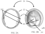
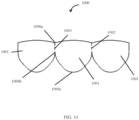
- the sinus gap 202 between the inner surface 21 of the conduit 20 and the leaflets 201 can be created by any means.
- the width W of the leaflets 201 may be shorter than the length of conduit between attachment points, D f . This arrangement is illustrated in FIG. 3.
- FIG. 3 This arrangement is illustrated in FIG. 3.
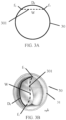
- FIG. 3A shows a simple diagram of the valve configuration in which the leaflet 301 of a valve encompassed by the embodiments described above is disposed within a conduit 30 such that the width, W (dashed line), of the leaflet 301 is shorter than the portion of the conduit, D f , between a first attachment point, f 1 , connecting the leaflet 301 to the inner surface 31 of the conduit 30 and a second attachment point, f 2 , connecting the leaflet to the inner surface 31 of the conduit 30.
- This valve configuration is further illustrated in FIG. 3B using the example valve depicted in FIG. 2B .
- the portion of the conduit, D f between the first attachment point, f 1 , and the second attachment point, f 2 , is longer than the width, W (dashed line), of the leaflet 301.
- a valve gap may be formed by the valve in a closed configuration.
- a multi-leaflet valve and at least a portion of a conduit inner surface may be disposed to form a valve gap 203 formed at the intersection of at least a portion of the inner surface of the conduit and a portion of the fan edge.
- FIG. 4 is an illustration of a valve 44 unfolded on single plane with the width, W, of the leaflet illustrated in FIG. 2B identified (dashed line).
- the leaflet may have additional features illustrated in FIG. 4 .
- FIG. 4 shows a valve 44 configured to create a two leaflets, 401a and 401b, a leaflet for a single leaflet valve or a leaflet for a three or four leaflet valve may include the same elements in a similar configuration.
- each leaflet 401a, 401b may further include a fan 410a, 410b having a fan edge 411a, 411b extending beyond the open sinus edge 404a, 404b away from the outer sinus edge 401a, 401b and inner sinus edge 402a, 402b.
- the fan 410a, 410b may allow the leaflets of the valve to contact one another or overlap when the valve is in the closed position (see FIG. 3B ) stopping flow of fluid through the valve.
- the fan 410a, 410b may have any shape, and in certain embodiments, the fan 410a, 410b may have a curved shape with a wide section on one side of the leaflet and a narrow section on the opposite side of the leaflet.
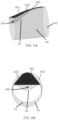
- the leaflet 54 may be attached to the inner surface 51 of the conduit 50 at the outer sinus edge 502a and 502b and the inner sinus edge 503a and 503b (503a is on the opposite side of the conduit 54).
- Each of the outer sinus edges 502a , 502b and inner sinus edge 503a , 503b may be attached to the conduit by a substantially fluid impervious connection such as, for example, suturing (as shown), fusion, applying an adhesive, or welding.
- the commissure 520 may also be attached to the inner surface 51 of the conduit 50 by, for example, suturing (as shown), applying an adhesive, or welding.
- the open sinus edge 504a , 504b are not attached to the conduit 50, and remain open to fluids flowing through the conduit 50.
- the opening creates a sinus 530a, 530b between the inner surface 51 of the conduit 50 and each leaflet 501a, 501b, and each open sinus edge 504a, 504b.
- FIG. 7C and FIG. 7D show the valve in operable configuration where the conduit has been reverted such that the valve is on the inner surface of the conduit 70 and conduit 70 has retained its cylindrical shape.
- the leaflet 701, which has an open edge 704 width, W, that is less than the circumference of the conduit 70 between attachment points may be suspended below the inner surface of the conduit 70 by a depth, W d , which varies with the length, B, of the leaflet 701 creating a sinus 730.
- the leaflet 701 may have a substantially triangular shape. Therefore, the leaflet width, W, may also vary with the length, B, of the leaflet 701.
- the material may be surface-modified to include a surface coating or a bioactive material.
- the surface coating or bioactive material may be an anti-coagulant coating or an anti-coagulant material that promotes biocompatibility such as, for example, coumadin, heparin, a heparin derivative, a Factor Xa inhibitor, a direct thrombin inhibitor, hementin, sintered porous titanium microspheres, a carbon coating, or combinations thereof.
- the material is non-stretchable. In some embodiments, the material is non-stretchable biocompatible and hemocompatible.
- Non-limiting examples of non-stretchable biocompatible and hemocompatible material that can be used to make the conduits or valve are polytetrafluoroethylene (PTFE), expanded polytetrafluoroethylene (ePTFE), polyethylene terephthalate (PET), polydimethyl siloxane (PDMS), polyethylene (PE), polypropylene (PP), polyesters, polycarbonates, polyvinyl chloride (PVC), hydrogels, and the like.
- the biocompatible and hemocompatible material may be a polymer coated with a bioactive coating. In some embodiments, the biocompatible and hemocompatible polymer may be surface-modified to include a bioactive material.
- the conduit may have a diameter in a range of about 40 mm to about 15 mm, about 25 mm to about 5 mm, about 20 mm to about 8 mm, about 15 mm to about 10 mm, or any range or individual diameter encompassed by these example ranges.
- the conduit may have a diameter in a range of about 2 mm to about 40 mm, about 2 mm to about 30 mm, about 2 mm to about 20 mm, about 2 mm to about 10 mm, about 2 mm to about 5 mm.
- the conduit may have a diameter in a range of about 5 mm to about 40 mm, about 10 mm to about 40 mm, about 20 mm to about 40 mm.
- the conduit diameter is 2 mm. In some embodiments, the conduit diameter is 3 mm. In some embodiments, the conduit diameter is 4 mm. In some embodiments, the conduit diameter is 5 mm. In some embodiments, the conduit diameter is 6 mm. In some embodiments, the conduit diameter is 7 mm. In some embodiments, the conduit diameter is 8 mm.
- each layer of a multi-layer conduit may be composed of the same material. In other embodiments, each layer of a multi-layer conduit may be composed of a different material. In further embodiments, each layer of a multi-layer conduit may be composed of a material characterized by different mechanical properties.
- an inner layer of a multi-layer conduit may include a material having a first yield strength and a first ultimate tensile strength and an outer layer that may include a second material having a second yield strength and/or a second ultimate tensile strength.
- the first yield strength may be greater than, about equal to, or less than the second yield strength.
- the first ultimate tensile strength may be greater than, about equal to, or less than the second ultimate tensile strength.
- an inner layer may include an elastic or plastically deformable material and an outer layer may include an inelastic or frangible material.
- the conduit is constructed from one or more layers of a material having a surface porosity.
- the surface porosity of one or more layers is about 1%. In some embodiments, the surface porosity of one or more layers is about 2%. In some embodiments, the surface porosity of one or more layers is about 3%. In some embodiments, the surface porosity of one or more layers is about 4%. In some embodiments, the surface porosity of one or more layers is about 5%. In some embodiments, the surface porosity of one or more layers is about 10%. In some embodiments, the surface porosity of one or more layers is about 15%. In some embodiments, the surface porosity of one or more layers is about 20%.
- the surface porosity of one or more layers is about 30%. In some embodiments, the surface porosity of one or more layers is about 40%. In some embodiments, the surface porosity of one or more layers is about 50%. In some embodiments, the surface porosity of one or more layers is about 60%. In some embodiments, the surface porosity of one or more layers is about 70%. In some embodiments, the surface porosity of one or more layers is about 80%. In some embodiments, the surface porosity of one or more layers is about 90%. In some embodiments, the surface porosity of one or more layers is less than 20%. In some embodiments, the surface porosity of one or more layers is less than 15%.
- the surface porosity of one or more layers is less than 10%. In some embodiments, the surface porosity of one or more layers is less than 5%. In some embodiments, the surface porosity of one or more layers is less than 4%. In some embodiments, the surface porosity of one or more layers is less than 3%. In some embodiments, the surface porosity of one or more layers is less than 2%. In some embodiments, the surface porosity of one or more layers is less than 1%. In some embodiments, the surface porosity of one or more layers is greater than 20%. In some embodiments, the surface porosity of one or more layers is greater than 30%. In some embodiments, the surface porosity of one or more layers is greater than 40%.
- the surface porosity of one or more layers is greater than 50%. In some embodiments, the surface porosity of one or more layers is greater than 60%. In some embodiments, the surface porosity of one or more layers is greater than 70%. In some embodiments, the surface porosity of one or more layers is greater than 80%. In some embodiments, the surface porosity of one or more layers is greater than 90%. In some embodiments, the surface porosity of one or more layers is in a range of about 1% to about 20%. In some embodiments, the surface porosity of one or more layers is in a range of about 1% to about 15%. In some embodiments, the surface porosity of one or more layers is in a range of about 1% to about 10%.
- the surface porosity of one or more layers is in a range of about 4% to about 20%. In some embodiments, the surface porosity of one or more layers is in a range of about 5% to about 20%. In some embodiments, the surface porosity of one or more layers is in a range of about 10% to about 20%. In some embodiments, the surface porosity of one or more layers is in a range of about 15% to about 20%. In some embodiments, the surface porosity of one or more layers is in a range of about 2% to about 15%. In some embodiments, the surface porosity of one or more layers is in a range of about 3% to about 10%.
- the surface porosity of one or more layers is in a range of about 4% to about 10%. In some embodiments, the surface porosity of one or more layers is in a range of about 5% to about 10%. In some embodiments, the surface porosity of one or more layers is in a range of about 5% to about 20%. In some embodiments, the surface porosity of one or more layers is in a range of about 5% to about 15%. In some embodiments, the surface porosity of one or more layers is in a range of about 5% to about 10%. In some embodiments, the surface porosity of one or more layers is in a range of about 20% to about 90%.
- the surface porosity of one or more layers is in a range of about 20% to about 80%. In some embodiments, the surface porosity of one or more layers is in a range of about 20% to about 70%. In some embodiments, the surface porosity of one or more layers is in a range of about 20% to about 60%. In some embodiments, the surface porosity of one or more layers is in a range of about 20% to about 50%. In some embodiments, the surface porosity of one or more layers is in a range of about 20% to about 40%. In some embodiments, the surface porosity of one or more layers is in a range of about 20% to about 30%. In some embodiments, the surface porosity of one or more layers is in a range of about 30% to about 90%.
- the surface porosity of one or more layers is in a range of about 40% to about 90%. In some embodiments, the surface porosity of one or more layers is in a range of about 50% to about 90%. In some embodiments, the surface porosity of one or more layers is in a range of about 60% to about 90%. In some embodiments, the surface porosity of one or more layers is in a range of about 70% to about 90%. In some embodiments, the surface porosity of one or more layers is in a range of about 80% to about 90%. In some embodiments, the surface porosity of one or more layers is in a range of about 30% to about 80%. In some embodiments, the surface porosity of one or more layers is in a range of about 30% to about 70%.
- the surface porosity of one or more layers is in a range of about 30% to about 60%. In some embodiments, the surface porosity of one or more layers is in a range of about 30% to about 50%. In some embodiments, the surface porosity of one or more layers is in a range of about 30% to about 40%. In some embodiments, the surface porosity of one or more layers is in a range of about 40% to about 80%. In some embodiments, the surface porosity of one or more layers is in a range of about 50% to about 80%. In some embodiments, the surface porosity of one or more layers is in a range of about 60% to about 80%.
- the surface porosity of one or more layers is in a range of about 70% to about 80%. In some embodiments, the surface porosity of one or more layers is in a range of about 40% to about 70%. In some embodiments, the surface porosity is in a range of about 40% to about 60%. In some embodiments, the surface porosity of one or more layers is in a range of about 40% to about 50%. In some embodiments, the surface porosity of one or more layers is in a range of about 50% to about 70%. In some embodiments, the surface porosity of one or more layers is in a range of about 60% to about 70%.
- Conduits composed of multiple layers may have expansion capabilities depending on the material properties of the multiple layers.
- a conduit comprising a biodegradable outer layer and an elastic or plastically deformable inner layer may be expanded due to the force of a fluid flowing therein but only after the outer layer has degraded.
- a conduit having an inelastic or frangible outer layer and an elastic or plastically deformable inner layer may remain in an unexpanded state until sufficient force, for example, supplied by an inserted expansion device, is applied internally to rupture the outer layer and thus permit the inner layer to expand.
- conduit materials, formulations, and/or mechanical properties may be constant over the longitudinal dimension of the conduit. In some embodiments, the conduit materials, formulations, and/or mechanical properties of the conduit may vary along the length or any partial length of the conduit. Conduits having multiple branches may have mechanical properties that differ between the branches and/or a main cylindrical tube of the conduit.
- the conduits described above may include additional components.
- the conduit may include a stent that is attached to or encapsulated by the material of the conduit, or an inner layer may include a stent while an outer layer may include an elastic or plastically deformable material.
- a conduit may be composed of a biodegradable outer layer and an elastic or plastically deformable inner layer.
- a multi-layer conduit may include a first inner layer comprising a woven material and a second outer layer comprising a woven material. It may be understood that the woven material composing the inner layer may be the same as the woven material composing the outer layer. Alternatively, the woven material composing the inner layer may differ from the woven material composing the outer layer.
- the conduit may comprise a valve.
- the valved conduit may include a conduit having a first conduit layer having an inner surface in physical communication with an outer surface of a second conduit layer and the valve is disposed within the second conduit layer.
- the first conduit layer may be composed of a first plastically deformable material having a yield strength of about 0.1 MPa to about 4 MPa
- the second conduit layer may be composed of the same plastically deformable material as the first layer.
- the multi-layer valved conduit may be composed of a first conduit layer having a first plastically deformable material having a yield strength of about 0.1 MPa to about 4 MPa, and a second conduit layer composed of a second material that may differ from the first material.
- the valved conduit may have a first conduit layer composed of a woven material, a second conduit layer composed of a woven material, or both the first conduit layer and the second conduit layer may each be composed of a woven material.
- the first conduit layer may be biodegradable.
- the first conduit layer may include a non-plastically deformable material.
- the multi-layer valved conduit may include a stent as part of the second conduit layer.
- the conduit has a yield strength. In some embodiments, the yield strength is about 0.1 MPa to about 4 MPa. In some embodiments, the yield strength is about 0.2 MPa to about 4 MPa. In some embodiments, the yield strength is about 0.3 MPa to about 4 MPa. In some embodiments, the yield strength is about 0.4 MPa to about 4 MPa. In some embodiments, the yield strength is about 0.5 MPa to about 4 MPa. In some embodiments, the yield strength is about 0.6 MPa to about 4 MPa. In some embodiments, the yield strength is about 0.7 MPa to about 4 MPa. In some embodiments, the yield strength is about 0.8 MPa to about 4 MPa.
- the yield strength is about 0.9 MPa to about 4 MPa. In some embodiments, the yield strength is about 1 MPa to about 4 MPa. In some embodiments, the yield strength is about 0.1 MPa to about 0.2 MPa. In some embodiments, the yield strength is about 0.1 MPa to about 0.3 MPa. In some embodiments, the yield strength is about 0.1 MPa to about 0.4 MPa. In some embodiments, the yield strength is about 0.1 MPa to about 0.5 MPa. In some embodiments, the yield strength is about 0.1 MPa to about 0.6 MPa. In some embodiments, the yield strength is about 0.1 MPa to about 0.7 MPa. In some embodiments, the yield strength is about 0.1 MPa to about 0.8 MPa.
- the yield strength is about 0.1 MPa to about 0.9 MPa. In some embodiments, the yield strength is about 0.1 MPa to about 1 MPa. In some embodiments, the yield strength is about 0.1 MPa to about 12 MPa. In some embodiments, the yield strength is about 0.1 MPa to about 11 MPa. In some embodiments, the yield strength is about 0.1 MPa to about 10 MPa. In some embodiments, the yield strength is about 0.1 MPa to about 9 MPa. In some embodiments, the yield strength is about 0.1 MPa to about 8 MPa. In some embodiments, the yield strength is about 0.1 MPa to about 7 MPa. In some embodiments, the yield strength is about 0.1 MPa to about 6 MPa.
- the yield strength is about 0.1 MPa to about 5 MPa. In some embodiments, the yield strength is about 0.2 MPa to about 12 MPa. In some embodiments, the yield strength is about 0.2 MPa to about 11 MPa. In some embodiments, the yield strength is about 0.2 MPa to about 10 MPa. In some embodiments, the yield strength is about 0.2 MPa to about 9 MPa. In some embodiments, the yield strength is about 0.2 MPa to about 8 MPa. In some embodiments, the yield strength is about 0.2 MPa to about 7 MPa. In some embodiments, the yield strength is about 0.2 MPa to about 6 MPa. In some embodiments, the yield strength is about 0.2 MPa to about 5 MPa.
- the yield strength is about 0.4 MPa to about 11 MPa. In some embodiments, the yield strength is about 0.4 MPa to about 10 MPa. In some embodiments, the yield strength is about 0.4 MPa to about 9 MPa. In some embodiments, the yield strength is about 0.4 MPa to about 8 MPa. In some embodiments, the yield strength is about 0.4 MPa to about 7 MPa. In some embodiments, the yield strength is about 0.4 MPa to about 6 MPa. In some embodiments, the yield strength is about 0.4 MPa to about 5 MPa. In some embodiments, the yield strength is about 0.5 MPa to about 12 MPa. In some embodiments, the yield strength is about 0.5 MPa to about 11 MPa.
- the yield strength is about 0.5 MPa to about 10 MPa. In some embodiments, the yield strength is about 0.5 MPa to about 9 MPa. In some embodiments, the yield strength is about 0.5 MPa to about 8 MPa. In some embodiments, the yield strength is about 0.5 MPa to about 7 MPa. In some embodiments, the yield strength is about 0.5 MPa to about 6 MPa. In some embodiments, the yield strength is about 0.5 MPa to about 5 MPa. In some embodiments, the yield strength is about 0.6 MPa to about 12 MPa. In some embodiments, the yield strength is about 0.6 MPa to about 11 MPa. In some embodiments, the yield strength is about 0.6 MPa to about 10 MPa.
- the yield strength is about 4 MPa to about 8 MPa. In some embodiments, the yield strength is about 4 MPa to about 7 MPa. In some embodiments, the yield strength is about 4 MPa to about 6 MPa. In some embodiments, the yield strength is about 4 MPa to about 5 MPa. In some embodiments, the yield strength is about 5 MPa to about 12 MPa. In some embodiments, the yield strength is about 5 MPa to about 11 MPa. In some embodiments, the yield strength is about 5 MPa to about 10 MPa. In some embodiments, the yield strength is about 5 MPa to about 9 MPa. In some embodiments, the yield strength is about 5 MPa to about 8 MPa. In some embodiments, the yield strength is about 5 MPa to about 7 MPa.
- the yield strength is about 5 MPa to about 6 MPa. In some embodiments, the yield strength is about 6 MPa to about 12 MPa. In some embodiments, the yield strength is about 6 MPa to about 11 MPa. In some embodiments, the yield strength is about 6 MPa to about 10 MPa. In some embodiments, the yield strength is about 6 MPa to about 9 MPa. In some embodiments, the yield strength is about 6 MPa to about 8 MPa. In some embodiments, the yield strength is about 6 MPa to about 7 MPa. In some embodiments, the yield strength is about 7 MPa to about 12 MPa. In some embodiments, the yield strength is about 7 MPa to about 11 MPa. In some embodiments, the yield strength is about 7 MPa to about 10 MPa.
- the yield strength is about 10 MPa to about 11 MPa. In some embodiments, the yield strength is about 0.1 MPa. In some embodiments, the yield strength is about 0.2 MPa. In some embodiments, the yield strength is about 0.3 MPa. In some embodiments, the yield strength is about 0.4 MPa. In some embodiments, the yield strength is about 0.5 MPa. In some embodiments, the yield strength is about 0.6 MPa. In some embodiments, the yield strength is about 0.7 MPa. In some embodiments, the yield strength is about 0.8 MPa. In some embodiments, the yield strength is about 0.9 MPa. In some embodiments, the yield strength is about 1 MPa. In some embodiments, the yield strength is about 2 MPa.
- the yield strength is about 3 MPa. In some embodiments, the yield strength is about 4 MPa. In some embodiments, the yield strength is about 5 MPa. In some embodiments, the yield strength is about 6 MPa. In some embodiments, the yield strength is about 7 MPa. In some embodiments, the yield strength is about 8 MPa. In some embodiments, the yield strength is about 9 MPa. In some embodiments, the yield strength is about 10 MPa. In some embodiments, the yield strength is about 11 MPa. In some embodiments, the yield strength is about 12 MPa.
- the valve 100, 44, 1102 or leaflet 201, 301, 54, 601, 701, and 801 may have a thickness of about 0.05 mm to about 0.3 mm in various embodiments, and this thickness may vary within the valve.
- the valve may comprise a material having a a thickness or total thickness of about 0.05 mm to about 0.3 mm, about 0.1 mm to about 0.3 mm, about 0.15 mm to about 0.3 mm, about 0.2 mm to about 0.3 mm, about 0.25 mm to about 0.3 mm, about 0.05 mm to about 0.25 mm, about 0.1 mm to about 0.25 mm, about 0.2 mm to about 0.25 mm, about 0.05 mm to about 0.2 mm, about 0.1 mm to about 0.2 mm, about 0.15 mm to about 0.2 mm, or a value within any of these range.
- the sinus portion of the leaflet may have a greater thickness than the fan portion or the fan portion may have a greater thickness than the sinus portion of the leaflet.
- the thickness of the valve may be selected to provide sufficient flexibility to allow the valve to obtain the open and closed configurations under the pressure of the flow of fluid through the conduit.
- the dimensions of each leaflet may vary depending on the diameter of the conduit and the number of leaflets making up the valve. For example with reference to FIG.
- ratio the length, B, of a leaflet 701, and the width, W, leaflet may be about 0.2 to about 2, about 0.3 to about 2, about 0.4 to about 2, about 0.5 to about 2, about 0.6 to about 2, about 0.75 to about 2, about 1 to about 2, about 1 to about 1, or any ratio therebetween or any ratio encompassed by these example ratios.
- the ratio of the width of the leaflet to a portion of the conduit circumference between the attachment points may be about 0.63 to about 1, about 0.7 to about 1, about 0.5 to about 1, or any ratio therebetween or any ratio encompassed by these example ratios.
- the ratio of the width, W, the leaflet 701 to the diameter of the conduit may be about 0.02 to about 3, about 0.05 to about 3, about 0.08 to about 3, about 0.1 to about 3, about 0.2 to about 3, about 0.5 to about 3, about 1 to about 3, about 0.9 to about 1.7, or any ratio therebetween or any ratio encompassed by these example ratios.
- the ratio between a length of the commissure 420 and the width, W, of the leaflet 401 may be about 0.05 to about 2, about 0.1 to about 2, about 0.2 to about 2, about 0.3 to about 2, about 0.5 to about 2, or any ratio therebetween or any ratio encompassed by these example ratios.
- the ratio of the inner sinus edge 703 the leaflet 701 to the width, W, of the leaflet 701 may be about 0.2 to about 2.5, about 0.3 to about 2.5, about 0.4 to about 2.5, about 0.5 to about 2.5, about 0.6 to about 2.5, about 0.75 to about 2.5, about 1 to about 2.5, about 1 to about 1, or any ratio therebetween or any ratio encompassed by these example ratios.
- the width, W, of the leaflet 701 may be about 1 mm to about 10 mm, about 2 mm to about 7 mm, about 2 mm to about 5 mm, about 20mm to about 40 mm, about 10 mm to about 30 mm, or any individual width or range encompassed by these example widths.
- the length, B, of the leaflet 701 may be about 5 mm to about 40 mm, about 5 mm to about 30 mm, about 8 mm to about 25 mm, about 10 mm to about 20 mm, or any individual length, B, or range encompassed by these example lengths.
- the length of the inner sinus edge 703 about outer sinus edge 704 may each, individually, be about 5 mm to about 45 mm, about 5 mm to about 35 mm, about 8 mm to about 30 mm, about 10 mm to about 20 mm, or any individual length or range encompassed by these example lengths.
- the surface porosity is in a range of about 1% to about 4%. In some embodiments, the surface porosity is in a range of about 1% to about 3%. In some embodiments, the surface porosity is in a range of about 1% to about 2%. In some embodiments, the surface porosity is in a range of about 1% to about 8%. In some embodiments, the surface porosity is in a range of about 2% to about 8%. In some embodiments, the surface porosity is in a range of about 3% to about 8%. In some embodiments, the surface porosity is in a range of about 4% to about 8%. In some embodiments, the surface porosity is in a range of about 1% to about 7%.
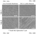
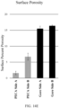
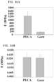
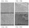
- the PECA Conduit comprises a multi-layer conduit made of ePTFE having a luminal surface porosity of about 4%, an abluminal surface porosity of greater than 20%, a total luminal-layer thickness of 0.045 mm, and a total abluminal layer thickness of about 1mm.
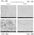
- the PECA Conduit was compared to the Gore Preclude Membrane having a total thickness of 0.1 mm in a blood-contacting environment and the BARD Impra Conduit having a surface porosity of >20%.
- FIG. 19A A significantly lower amount of activated platelet adhesion and fibroblastic activity was observed in the luminal surface of the PECA Conduit ( FIG. 19A ) when compared to the Gore Preclude Membrane ( FIG. 19C ). Higher amounts of growth were seen on both the abluminal surface of the PECA Conduit ( FIG. 19B ) and BARD Impra Conduit ( FIG. 19D ).
- the valve, wherein the layer may have a thickness of less than or about 0.1 mm.
- the valve, wherein the one or more leaflets may comprise more than one layer of the material.
- the valve, wherein the one or more leaflets may have a total thickness of less than or about 0.1 mm.
- valved conduit wherein the material may be a fluoropolymer.
- valved conduit wherein the layer may include a surface coating.
- valved conduit wherein the layer may have an average pore area less than or about 1 square micron.
- valved conduit wherein the layer may have an average pore diameter less than or about 1 micron.
- valved conduit wherein at least two layers of the more than one layer may be anisotropic with orientations that are offset by an angle of at least 10 degrees.
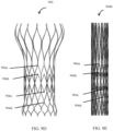
- a transcatheter stent comprising: a stent having chevron shaped structures disposed in two annular rows opposing each other, the stent having an inner surface and an outer surface and a collapsed configuration and an expanded configuration; and a valve attached to the inner surface of the stent at a plurality of attachment points, each attachment point being at a median vertex of the chevron shaped structure.
- the transcatheter stent wherein the plurality of attachment points may comprise at least one pair of attachment points, wherein a distance between each attachment point of the pair of attachment points is substantially the same in the collapsed configuration and the expanded configuration.
- the transcatheter stent wherein the plurality of attachment points may comprise at least one pair of attachment points that rotate between collapsed configuration and the expanded configuration.
- the transcatheter stent wherein the plurality of attachment points may comprise at least one pair of attachment points that undergo equal translation between the collapsed configuration and the expanded configuration.
- transcatheter stent wherein a distance between each attachment point of each pair of attachment points may be substantially the same in the collapsed configuration and the expanded configuration, and a distance between two pairs of attachment points is substantially the same in the collapsed configuration and the expanded configuration.
- the transcatheter stent wherein at least one pair of attachment points may undergo equal translation between the collapsed configuration and the expanded configuration.
- transcatheter stent wherein a member associated with one attachment point of each pair of attachment points may rotate between the collapsed configuration and the expanded configuration.
- transcatheter stent wherein a member associated with one attachment point of each pair of attachment points may rotate during the transition between collapsed configuration and expanded configuration.
- a transcatheter stent comprising: a stent having a proximal portion and a distal portion each comprising a plurality of spindle-shaped structures, and an intermediate portion comprising chevron shaped structures disposed in annular rows opposing each other.
- the transcatheter stent may further comprise a valve disposed within the intermediate portion of the stent.
- the transcatheter stent wherein the valve may be attached to the intermediate portion of the stent at a plurality of attachment points at a median vertex of the chevron shaped structure.
- the transcatheter stent wherein the plurality of attachment points may comprise at least one pair of attachment points, wherein a distance between each attachment point of the pair is substantially the same in a collapsed configuration and an expanded configuration of the stent.
- the transcatheter stent wherein the stent may be made from cobalt, titanium, nickel, chromium, stainless steel, and alloys thereof, and any combination thereof.
- the transcatheter stent wherein the valve may comprise leaflets composed of a non-stretching material.
- a transcatheter stent comprising: a stent having chevron shaped structures disposed in two annular rows opposing each other, the stent having an inner surface and an outer surface and a collapsed configuration and an expanded configuration; and a valve attached to the inner surface of the stent at a plurality of attachment points, each attachment point being at a median vertex of the chevron shaped structure, the valve further comprising one or more leaflets constructed from at least two layers of a fluoropolymer, wherein the at least two layers are anisotropic with orientations that offset by an angle of at least 10 degrees.
Landscapes
- Health & Medical Sciences (AREA)
- Cardiology (AREA)
- Engineering & Computer Science (AREA)
- Biomedical Technology (AREA)
- Life Sciences & Earth Sciences (AREA)
- Transplantation (AREA)
- Heart & Thoracic Surgery (AREA)
- Vascular Medicine (AREA)
- Oral & Maxillofacial Surgery (AREA)
- Animal Behavior & Ethology (AREA)
- General Health & Medical Sciences (AREA)
- Public Health (AREA)
- Veterinary Medicine (AREA)
- Manufacturing & Machinery (AREA)
- Prostheses (AREA)
- Materials For Medical Uses (AREA)
Applications Claiming Priority (4)
| Application Number | Priority Date | Filing Date | Title |
|---|---|---|---|
| US201662406175P | 2016-10-10 | 2016-10-10 | |
| US201762532736P | 2017-07-14 | 2017-07-14 | |
| EP17860441.9A EP3522830B1 (de) | 2016-10-10 | 2017-10-10 | Transkatheterstent und ventilanordnung |
| PCT/US2017/055939 WO2018071417A1 (en) | 2016-10-10 | 2017-10-10 | Transcatheter stent and valve assembly |
Related Parent Applications (1)
| Application Number | Title | Priority Date | Filing Date |
|---|---|---|---|
| EP17860441.9A Division EP3522830B1 (de) | 2016-10-10 | 2017-10-10 | Transkatheterstent und ventilanordnung |
Publications (2)
| Publication Number | Publication Date |
|---|---|
| EP4397276A2 true EP4397276A2 (de) | 2024-07-10 |
| EP4397276A3 EP4397276A3 (de) | 2024-09-18 |
Family
ID=61830332
Family Applications (2)
| Application Number | Title | Priority Date | Filing Date |
|---|---|---|---|
| EP17860441.9A Active EP3522830B1 (de) | 2016-10-10 | 2017-10-10 | Transkatheterstent und ventilanordnung |
| EP24176940.5A Pending EP4397276A3 (de) | 2016-10-10 | 2017-10-10 | Transkatheter-stent- und ventilanordnung |
Family Applications Before (1)
| Application Number | Title | Priority Date | Filing Date |
|---|---|---|---|
| EP17860441.9A Active EP3522830B1 (de) | 2016-10-10 | 2017-10-10 | Transkatheterstent und ventilanordnung |
Country Status (3)
| Country | Link |
|---|---|
| US (5) | US10631979B2 (de) |
| EP (2) | EP3522830B1 (de) |
| WO (1) | WO2018071417A1 (de) |
Families Citing this family (26)
| Publication number | Priority date | Publication date | Assignee | Title |
|---|---|---|---|---|
| WO2013019756A2 (en) | 2011-07-29 | 2013-02-07 | Carnegie Mellon University | Artificial valved conduits for cardiac reconstructive procedures and methods for their production |
| JP6706069B2 (ja) | 2013-03-08 | 2020-06-03 | カーネギー メロン ユニバーシティ | 拡張可能埋込型導管 |
| US11000370B2 (en) | 2016-03-02 | 2021-05-11 | Peca Labs, Inc. | Expandable implantable conduit |
| US10631979B2 (en) | 2016-10-10 | 2020-04-28 | Peca Labs, Inc. | Transcatheter stent and valve assembly |
| US20190091013A1 (en) * | 2017-09-22 | 2019-03-28 | St. Jude Medical, Cardiology Division, Inc. | Prosthetic Heart Valve with Atraumatic Aortic Portion |
| WO2019195860A2 (en) | 2018-04-04 | 2019-10-10 | Vdyne, Llc | Devices and methods for anchoring transcatheter heart valve |
| US12186187B2 (en) | 2018-09-20 | 2025-01-07 | Vdyne, Inc. | Transcatheter deliverable prosthetic heart valves and methods of delivery |
| US11071627B2 (en) | 2018-10-18 | 2021-07-27 | Vdyne, Inc. | Orthogonally delivered transcatheter heart valve frame for valve in valve prosthesis |
| US10321995B1 (en) | 2018-09-20 | 2019-06-18 | Vdyne, Llc | Orthogonally delivered transcatheter heart valve replacement |
| US11344413B2 (en) | 2018-09-20 | 2022-05-31 | Vdyne, Inc. | Transcatheter deliverable prosthetic heart valves and methods of delivery |
| US11278437B2 (en) | 2018-12-08 | 2022-03-22 | Vdyne, Inc. | Compression capable annular frames for side delivery of transcatheter heart valve replacement |
| US10595994B1 (en) | 2018-09-20 | 2020-03-24 | Vdyne, Llc | Side-delivered transcatheter heart valve replacement |
| US11109969B2 (en) | 2018-10-22 | 2021-09-07 | Vdyne, Inc. | Guidewire delivery of transcatheter heart valve |
| US11253359B2 (en) | 2018-12-20 | 2022-02-22 | Vdyne, Inc. | Proximal tab for side-delivered transcatheter heart valves and methods of delivery |
| WO2020146842A1 (en) | 2019-01-10 | 2020-07-16 | Vdyne, Llc | Anchor hook for side-delivery transcatheter heart valve prosthesis |
| US11185409B2 (en) | 2019-01-26 | 2021-11-30 | Vdyne, Inc. | Collapsible inner flow control component for side-delivered transcatheter heart valve prosthesis |
| US11273032B2 (en) | 2019-01-26 | 2022-03-15 | Vdyne, Inc. | Collapsible inner flow control component for side-deliverable transcatheter heart valve prosthesis |
| CN113543750B (zh) | 2019-03-05 | 2025-10-10 | 维迪内股份有限公司 | 用于正交经导管心脏瓣膜假体的三尖瓣反流控制装置 |
| US11173027B2 (en) | 2019-03-14 | 2021-11-16 | Vdyne, Inc. | Side-deliverable transcatheter prosthetic valves and methods for delivering and anchoring the same |
| US11076956B2 (en) | 2019-03-14 | 2021-08-03 | Vdyne, Inc. | Proximal, distal, and anterior anchoring tabs for side-delivered transcatheter mitral valve prosthesis |
| AU2020267390B2 (en) | 2019-05-04 | 2025-12-04 | Vdyne, Inc. | Cinch device and method for deployment of a side-delivered prosthetic heart valve in a native annulus |
| JP7584500B2 (ja) | 2019-08-20 | 2024-11-15 | ブイダイン,インコーポレイテッド | 側方送達可能な経カテーテル人工弁の送達及び回収のデバイス及び方法 |
| CN114630665B (zh) | 2019-08-26 | 2025-06-17 | 维迪内股份有限公司 | 可侧面输送的经导管假体瓣膜及其输送和锚定方法 |
| US11234813B2 (en) | 2020-01-17 | 2022-02-01 | Vdyne, Inc. | Ventricular stability elements for side-deliverable prosthetic heart valves and methods of delivery |
| EP4601585A1 (de) | 2022-10-14 | 2025-08-20 | Vdyne, Inc. | Vorrichtungen und verfahren zur freisetzung einer herzklappenprothese mit supraannularer stütze |
| WO2025251026A1 (en) * | 2024-05-31 | 2025-12-04 | Peca Labs, Inc. | Polymer materials with medical applications and methods for manufacturing |
Family Cites Families (102)
| Publication number | Priority date | Publication date | Assignee | Title |
|---|---|---|---|---|
| CA962021A (en) | 1970-05-21 | 1975-02-04 | Robert W. Gore | Porous products and process therefor |
| US6436135B1 (en) | 1974-10-24 | 2002-08-20 | David Goldfarb | Prosthetic vascular graft |
| US4160688A (en) | 1977-02-03 | 1979-07-10 | Johns-Manville Corporation | Low profile heat sealing iron |
| US4475972A (en) | 1981-10-01 | 1984-10-09 | Ontario Research Foundation | Implantable material |
| US4816339A (en) | 1987-04-28 | 1989-03-28 | Baxter International Inc. | Multi-layered poly(tetrafluoroethylene)/elastomer materials useful for in vivo implantation |
| US4955899A (en) | 1989-05-26 | 1990-09-11 | Impra, Inc. | Longitudinally compliant vascular graft |
| US5258023A (en) | 1992-02-12 | 1993-11-02 | Reger Medical Development, Inc. | Prosthetic heart valve |
| US5466261A (en) | 1992-11-19 | 1995-11-14 | Wright Medical Technology, Inc. | Non-invasive expandable prosthesis for growing children |
| CA2132011C (en) | 1993-01-14 | 1999-08-10 | Peter J. Schmitt | Radially expandable tubular prosthesis |
| US5529830A (en) | 1994-05-25 | 1996-06-25 | W. L. Gore & Associates, Inc. | Two-way stretchable fabric laminate and articles made from it |
| US6863686B2 (en) | 1995-04-17 | 2005-03-08 | Donald Shannon | Radially expandable tape-reinforced vascular grafts |
| US5800512A (en) | 1996-01-22 | 1998-09-01 | Meadox Medicals, Inc. | PTFE vascular graft |
| US5843161A (en) | 1996-06-26 | 1998-12-01 | Cordis Corporation | Endoprosthesis assembly for percutaneous deployment and method of deploying same |
| US6016848A (en) | 1996-07-16 | 2000-01-25 | W. L. Gore & Associates, Inc. | Fluoropolymer tubes and methods of making same |
| US5824050A (en) | 1996-12-03 | 1998-10-20 | Atrium Medical Corporation | Prosthesis with in-wall modulation |
| US7452371B2 (en) | 1999-06-02 | 2008-11-18 | Cook Incorporated | Implantable vascular device |
| US6254636B1 (en) | 1998-06-26 | 2001-07-03 | St. Jude Medical, Inc. | Single suture biological tissue aortic stentless valve |
| WO2000038595A1 (fr) | 1998-12-28 | 2000-07-06 | Alexandr Vasilievich Samkov | Prothese de valvule du coeur |
| US6517571B1 (en) | 1999-01-22 | 2003-02-11 | Gore Enterprise Holdings, Inc. | Vascular graft with improved flow surfaces |
| US6736845B2 (en) | 1999-01-26 | 2004-05-18 | Edwards Lifesciences Corporation | Holder for flexible heart valve |
| US6558418B2 (en) | 1999-01-26 | 2003-05-06 | Edwards Lifesciences Corporation | Flexible heart valve |
| DE60134625D1 (de) | 2000-01-27 | 2008-08-14 | 3F Therapeutics Inc | Herzklappenprothese |
| US6517576B2 (en) | 2000-12-11 | 2003-02-11 | Shlomo Gabbay | Implantable patch prosthesis having one or more cusps for improved competency |
| US6503272B2 (en) | 2001-03-21 | 2003-01-07 | Cordis Corporation | Stent-based venous valves |
| WO2002087474A1 (en) | 2001-05-01 | 2002-11-07 | Imperial Medical Devices Limited | Valve prosthesis |
| US6936067B2 (en) | 2001-05-17 | 2005-08-30 | St. Jude Medical Inc. | Prosthetic heart valve with slit stent |
| US6716239B2 (en) | 2001-07-03 | 2004-04-06 | Scimed Life Systems, Inc. | ePTFE graft with axial elongation properties |
| US6939372B2 (en) | 2001-07-03 | 2005-09-06 | Scimed Life Systems, Inc. | Low profile, high stretch, low dilation knit prosthetic device |
| AU2002320610A1 (en) | 2001-07-16 | 2003-03-03 | Altertek/Bio Inc | Tissue engineered heart valve |
| GB0125925D0 (en) | 2001-10-29 | 2001-12-19 | Univ Glasgow | Mitral valve prosthesis |
| US20030114924A1 (en) | 2001-12-18 | 2003-06-19 | Riyad Moe | Polymer heart valve |
| US7018404B2 (en) | 2002-01-24 | 2006-03-28 | St. Jude Medical, Inc. | Conduit for aorta or pulmonary artery replacement |
| US6752828B2 (en) | 2002-04-03 | 2004-06-22 | Scimed Life Systems, Inc. | Artificial valve |
| AU2003234505A1 (en) | 2002-05-03 | 2003-11-17 | The General Hospital Corporation | Involuted endovascular valve and method of construction |
| US7789908B2 (en) | 2002-06-25 | 2010-09-07 | Boston Scientific Scimed, Inc. | Elastomerically impregnated ePTFE to enhance stretch and recovery properties for vascular grafts and coverings |
| US6971813B2 (en) | 2002-09-27 | 2005-12-06 | Labcoat, Ltd. | Contact coating of prostheses |
| TW590007U (en) | 2003-06-06 | 2004-06-01 | Univ Tamkang | Tri-leaflet mechanical heart valve |
| WO2005011534A1 (en) | 2003-07-31 | 2005-02-10 | Cook Incorporated | Prosthetic valve devices and methods of making such devices |
| WO2005011535A2 (en) | 2003-07-31 | 2005-02-10 | Cook Incorporated | Prosthetic valve for implantation in a body vessel |
| US7153325B2 (en) | 2003-08-01 | 2006-12-26 | Ultra-Kinetics, Inc. | Prosthetic intervertebral disc and methods for using the same |
| DE10340265A1 (de) | 2003-08-29 | 2005-04-07 | Sievers, Hans-Hinrich, Prof. Dr.med. | Prothese zum Ersatz der Aorten- und/oder Mitralklappe des Herzens |
| US7070616B2 (en) | 2003-10-31 | 2006-07-04 | Cordis Corporation | Implantable valvular prosthesis |
| US7261732B2 (en) * | 2003-12-22 | 2007-08-28 | Henri Justino | Stent mounted valve |
| US20050228495A1 (en) | 2004-01-15 | 2005-10-13 | Macoviak John A | Suspended heart valve devices, systems, and methods for supplementing, repairing, or replacing a native heart valve |
| US8377110B2 (en) | 2004-04-08 | 2013-02-19 | Endologix, Inc. | Endolumenal vascular prosthesis with neointima inhibiting polymeric sleeve |
| US20060122693A1 (en) | 2004-05-10 | 2006-06-08 | Youssef Biadillah | Stent valve and method of manufacturing same |
| US7794490B2 (en) | 2004-06-22 | 2010-09-14 | Boston Scientific Scimed, Inc. | Implantable medical devices with antimicrobial and biodegradable matrices |
| WO2006060546A2 (en) | 2004-12-01 | 2006-06-08 | Cook Incorporated | Valve with leak path |
| US20060149366A1 (en) | 2004-12-31 | 2006-07-06 | Jamie Henderson | Sintered structures for vascular graft |
| US20060149363A1 (en) | 2005-01-06 | 2006-07-06 | Scimed Life Systems, Inc. | Optimally expanded, collagen sealed ePTFE graft with improved tissue ingrowth |
| US7867274B2 (en) | 2005-02-23 | 2011-01-11 | Boston Scientific Scimed, Inc. | Valve apparatus, system and method |
| US7462156B2 (en) | 2005-04-11 | 2008-12-09 | Zan Mitrev | Replacement aortic valve leaflets and related technology |
| US7914569B2 (en) | 2005-05-13 | 2011-03-29 | Medtronics Corevalve Llc | Heart valve prosthesis and methods of manufacture and use |
| US8475512B2 (en) | 2005-05-17 | 2013-07-02 | Cook Medical Technologies Llc | Prosthetic valve devices and methods of making and using such devices |
| JP4912395B2 (ja) | 2005-05-24 | 2012-04-11 | エドワーズ ライフサイエンシーズ コーポレイション | 迅速配置式補綴用心臓弁 |
| US7306729B2 (en) | 2005-07-18 | 2007-12-11 | Gore Enterprise Holdings, Inc. | Porous PTFE materials and articles produced therefrom |
| US20070027528A1 (en) | 2005-07-29 | 2007-02-01 | Cook Incorporated | Elliptical implantable device |
| US20070043431A1 (en) | 2005-08-19 | 2007-02-22 | Cook Incorporated | Prosthetic valve |
| US7569071B2 (en) | 2005-09-21 | 2009-08-04 | Boston Scientific Scimed, Inc. | Venous valve, system, and method with sinus pocket |
| US8721704B2 (en) | 2006-04-21 | 2014-05-13 | W. L. Gore & Associates, Inc. | Expandable stent with wrinkle-free elastomeric cover |
| WO2007137211A2 (en) | 2006-05-22 | 2007-11-29 | Tarun John Edwin | Tissue synthetic-biomaterial hybrid medical devices |
| US20130331926A1 (en) | 2006-05-26 | 2013-12-12 | Abbott Cardiovascular Systems Inc. | Stents With Radiopaque Markers |
| US20130150943A1 (en) | 2007-01-19 | 2013-06-13 | Elixir Medical Corporation | Biodegradable endoprostheses and methods for their fabrication |
| EP2117613A1 (de) * | 2007-02-16 | 2009-11-18 | Cinvention Ag | Stents mit kohlenstoffbeschichtung |
| EP1958598A1 (de) | 2007-02-16 | 2008-08-20 | Universität Zürich | Wachstumsfähige, rohrförmige Stützprothese |
| WO2008106338A2 (en) | 2007-02-28 | 2008-09-04 | Medtronic, Inc. | Implantable medical device system with fixation member |
| FR2915678B1 (fr) | 2007-05-02 | 2010-04-16 | Lapeyre Ind Llc | Valve cardiaque prothetique mecanique |
| US8715337B2 (en) | 2007-11-09 | 2014-05-06 | Cook Medical Technologies Llc | Aortic valve stent graft |
| US8696743B2 (en) | 2008-04-23 | 2014-04-15 | Medtronic, Inc. | Tissue attachment devices and methods for prosthetic heart valves |
| US20090276040A1 (en) | 2008-05-01 | 2009-11-05 | Edwards Lifesciences Corporation | Device and method for replacing mitral valve |
| AU2009271574B2 (en) | 2008-07-15 | 2015-05-21 | St. Jude Medical, Inc. | Axially anchoring collapsible and re-expandable prosthetic heart valves for various disease states |
| WO2010011878A2 (en) | 2008-07-24 | 2010-01-28 | Cook Incorporated | Valve device with biased leaflets |
| CA2760461C (en) | 2009-04-29 | 2014-10-07 | The Cleveland Clinic Foundation | Apparatus and method for replacing a diseased cardiac valve |
| US8075611B2 (en) | 2009-06-02 | 2011-12-13 | Medtronic, Inc. | Stented prosthetic heart valves |
| US8936634B2 (en) | 2009-07-15 | 2015-01-20 | W. L. Gore & Associates, Inc. | Self constraining radially expandable medical devices |
| BR112012008334B8 (pt) | 2009-09-16 | 2021-06-22 | Bentley Innomed Gmbh | implante médico para dilatação e sustentação de um vaso do corpo a partir de seu lado interno |
| US20110094592A1 (en) | 2009-10-22 | 2011-04-28 | Howard Cheng | Fluid Check Valve with a Floating Pivot |
| WO2012018779A2 (en) | 2010-08-02 | 2012-02-09 | Children's Medical Center Corporation | Expandable valve and method of use |
| CN103687574B (zh) | 2011-02-25 | 2015-11-25 | 康涅狄格州大学 | 人工心脏瓣膜 |
| US8900652B1 (en) | 2011-03-14 | 2014-12-02 | Innovatech, Llc | Marked fluoropolymer surfaces and method of manufacturing same |
| EP2522308B1 (de) | 2011-05-10 | 2015-02-25 | Biotronik AG | Mechanische Transkatheter-Herzklappenprothese |
| US10745555B2 (en) * | 2011-06-23 | 2020-08-18 | Solvay Specialty Polymer Italy S.P.A. | Process for manufacturing porous membranes |
| US8603162B2 (en) | 2011-07-06 | 2013-12-10 | Waseda University | Stentless artificial mitral valve |
| US10117542B2 (en) | 2011-07-20 | 2018-11-06 | Luminaire Coffee LLC | Coffee maker |
| WO2013019756A2 (en) * | 2011-07-29 | 2013-02-07 | Carnegie Mellon University | Artificial valved conduits for cardiac reconstructive procedures and methods for their production |
| US9510935B2 (en) | 2012-01-16 | 2016-12-06 | W. L. Gore & Associates, Inc. | Articles including expanded polytetrafluoroethylene membranes with serpentine fibrils and having a discontinuous fluoropolymer layer thereon |
| US9023098B2 (en) | 2012-03-28 | 2015-05-05 | Medtronic, Inc. | Dual valve prosthesis for transcatheter valve implantation |
| US20130304196A1 (en) | 2012-05-08 | 2013-11-14 | Medtronic Vascular, Inc. | Prosthetic venous valve having leaflets forming a scalloped commissure |
| WO2014008207A1 (en) | 2012-07-02 | 2014-01-09 | Boston Scientific Scimed, Inc. | Prosthetic heart valve formation |
| US9283072B2 (en) | 2012-07-25 | 2016-03-15 | W. L. Gore & Associates, Inc. | Everting transcatheter valve and methods |
| US10376360B2 (en) * | 2012-07-27 | 2019-08-13 | W. L. Gore & Associates, Inc. | Multi-frame prosthetic valve apparatus and methods |
| JP6706069B2 (ja) | 2013-03-08 | 2020-06-03 | カーネギー メロン ユニバーシティ | 拡張可能埋込型導管 |
| EP2967863B1 (de) | 2013-03-15 | 2018-01-31 | Edwards Lifesciences Corporation | Aortenleitungen mit klappen |
| BR112015026425B1 (pt) | 2013-04-19 | 2021-11-23 | Strait Access Technologies Holdings (Pty) Ltd | Prótese de válvula cardíaca, stent e folheto |
| EP2991585B1 (de) | 2013-05-03 | 2023-08-16 | Medtronic Inc. | Medizinische vorrichtungen zur implantation in einer klappe |
| CA2914094C (en) | 2014-06-20 | 2021-01-05 | Edwards Lifesciences Corporation | Surgical heart valves identifiable post-implant |
| CN106659567B (zh) * | 2014-08-18 | 2019-06-14 | W.L.戈尔及同仁股份有限公司 | 带有用于假体瓣膜的一体缝合封套的框架 |
| US10507101B2 (en) * | 2014-10-13 | 2019-12-17 | W. L. Gore & Associates, Inc. | Valved conduit |
| EP3261589B1 (de) * | 2015-02-26 | 2020-09-16 | Merit Medical Systems, Inc. | Geschichtete medizinische anwendungen |
| EP3310297A4 (de) | 2015-06-18 | 2019-02-20 | Peca Labs, Inc. | Mit ventil versehener kanal und verfahren zur herstellung davon |
| US11000370B2 (en) | 2016-03-02 | 2021-05-11 | Peca Labs, Inc. | Expandable implantable conduit |
| US10631979B2 (en) | 2016-10-10 | 2020-04-28 | Peca Labs, Inc. | Transcatheter stent and valve assembly |
-
2017
- 2017-10-10 US US15/729,545 patent/US10631979B2/en active Active
- 2017-10-10 US US15/729,580 patent/US10610357B2/en active Active
- 2017-10-10 EP EP17860441.9A patent/EP3522830B1/de active Active
- 2017-10-10 WO PCT/US2017/055939 patent/WO2018071417A1/en not_active Ceased
- 2017-10-10 EP EP24176940.5A patent/EP4397276A3/de active Pending
-
2020
- 2020-02-27 US US16/803,892 patent/US20200268510A1/en not_active Abandoned
- 2020-02-27 US US16/803,852 patent/US20200268509A1/en not_active Abandoned
-
2023
- 2023-11-27 US US18/520,188 patent/US20240091001A1/en active Pending
Also Published As
| Publication number | Publication date |
|---|---|
| US20180098845A1 (en) | 2018-04-12 |
| WO2018071417A1 (en) | 2018-04-19 |
| US20240091001A1 (en) | 2024-03-21 |
| US20200268509A1 (en) | 2020-08-27 |
| EP3522830A1 (de) | 2019-08-14 |
| US20200268510A1 (en) | 2020-08-27 |
| US10610357B2 (en) | 2020-04-07 |
| EP4397276A3 (de) | 2024-09-18 |
| EP3522830B1 (de) | 2024-05-22 |
| US10631979B2 (en) | 2020-04-28 |
| EP3522830C0 (de) | 2024-05-22 |
| EP3522830A4 (de) | 2020-06-17 |
| US20180098844A1 (en) | 2018-04-12 |
Similar Documents
| Publication | Publication Date | Title |
|---|---|---|
| US20240091001A1 (en) | Transcatheter stent and valve assembly | |
| JP7507720B2 (ja) | 人工弁、枠及びリーフレット及びその製造方法 | |
| JP7237039B2 (ja) | 反転型の経カテーテル的弁とその方法 | |
| US10314700B2 (en) | Synthetic composite structures | |
| JP6392778B2 (ja) | 人工心臓弁リーフレットにおける曲げ特性の幾何学的制御 | |
| JP6463693B2 (ja) | 幾何学的形状の人工心臓弁 | |
| US20180168795A1 (en) | Valved conduit and method for fabricating same | |
| HK40113598A (en) | Transcatheter stent and valve assembly | |
| HK40012582A (en) | Transcatheter stent and valve assembly | |
| HK40012582B (en) | Transcatheter stent and valve assembly | |
| WO2025251026A1 (en) | Polymer materials with medical applications and methods for manufacturing | |
| HK1215145B (en) | Prosthetic valves, frames and leaflets |
Legal Events
| Date | Code | Title | Description |
|---|---|---|---|
| PUAI | Public reference made under article 153(3) epc to a published international application that has entered the european phase |
Free format text: ORIGINAL CODE: 0009012 |
|
| STAA | Information on the status of an ep patent application or granted ep patent |
Free format text: STATUS: THE APPLICATION HAS BEEN PUBLISHED |
|
| AC | Divisional application: reference to earlier application |
Ref document number: 3522830 Country of ref document: EP Kind code of ref document: P |
|
| AK | Designated contracting states |
Kind code of ref document: A2 Designated state(s): AL AT BE BG CH CY CZ DE DK EE ES FI FR GB GR HR HU IE IS IT LI LT LU LV MC MK MT NL NO PL PT RO RS SE SI SK SM TR |
|
| REG | Reference to a national code |
Ref country code: DE Ref legal event code: R079 Free format text: PREVIOUS MAIN CLASS: A61F0002040000 Ipc: A61F0002240000 |
|
| PUAL | Search report despatched |
Free format text: ORIGINAL CODE: 0009013 |
|
| AK | Designated contracting states |
Kind code of ref document: A3 Designated state(s): AL AT BE BG CH CY CZ DE DK EE ES FI FR GB GR HR HU IE IS IT LI LT LU LV MC MK MT NL NO PL PT RO RS SE SI SK SM TR |
|
| RIC1 | Information provided on ipc code assigned before grant |
Ipc: A61F 2/04 20130101ALI20240809BHEP Ipc: A61F 2/02 20060101ALI20240809BHEP Ipc: A61F 2/24 20060101AFI20240809BHEP |
|
| REG | Reference to a national code |
Ref country code: HK Ref legal event code: DE Ref document number: 40113598 Country of ref document: HK |
|
| STAA | Information on the status of an ep patent application or granted ep patent |
Free format text: STATUS: REQUEST FOR EXAMINATION WAS MADE |
|
| 17P | Request for examination filed |
Effective date: 20250318 |