EP4397361A2 - Vorrichtungen zur verabreichung elektrischer stimulation zur behandlung von krebs - Google Patents
Vorrichtungen zur verabreichung elektrischer stimulation zur behandlung von krebs Download PDFInfo
- Publication number
- EP4397361A2 EP4397361A2 EP24171875.8A EP24171875A EP4397361A2 EP 4397361 A2 EP4397361 A2 EP 4397361A2 EP 24171875 A EP24171875 A EP 24171875A EP 4397361 A2 EP4397361 A2 EP 4397361A2
- Authority
- EP
- European Patent Office
- Prior art keywords
- electric field
- cancerous tumor
- impedance
- site
- medical device
- Prior art date
- Legal status (The legal status is an assumption and is not a legal conclusion. Google has not performed a legal analysis and makes no representation as to the accuracy of the status listed.)
- Granted
Links
Images









Classifications
-
- A—HUMAN NECESSITIES
- A61—MEDICAL OR VETERINARY SCIENCE; HYGIENE
- A61N—ELECTROTHERAPY; MAGNETOTHERAPY; RADIATION THERAPY; ULTRASOUND THERAPY
- A61N1/00—Electrotherapy; Circuits therefor
- A61N1/18—Applying electric currents by contact electrodes
- A61N1/32—Applying electric currents by contact electrodes alternating or intermittent currents
- A61N1/36—Applying electric currents by contact electrodes alternating or intermittent currents for stimulation
- A61N1/36002—Cancer treatment, e.g. tumour
-
- A—HUMAN NECESSITIES
- A61—MEDICAL OR VETERINARY SCIENCE; HYGIENE
- A61N—ELECTROTHERAPY; MAGNETOTHERAPY; RADIATION THERAPY; ULTRASOUND THERAPY
- A61N1/00—Electrotherapy; Circuits therefor
- A61N1/02—Details
- A61N1/04—Electrodes
- A61N1/05—Electrodes for implantation or insertion into the body, e.g. heart electrode
-
- A—HUMAN NECESSITIES
- A61—MEDICAL OR VETERINARY SCIENCE; HYGIENE
- A61N—ELECTROTHERAPY; MAGNETOTHERAPY; RADIATION THERAPY; ULTRASOUND THERAPY
- A61N1/00—Electrotherapy; Circuits therefor
- A61N1/18—Applying electric currents by contact electrodes
- A61N1/32—Applying electric currents by contact electrodes alternating or intermittent currents
- A61N1/36—Applying electric currents by contact electrodes alternating or intermittent currents for stimulation
- A61N1/3605—Implantable neurostimulators for stimulating central or peripheral nerve system
- A61N1/36128—Control systems
- A61N1/36135—Control systems using physiological parameters
- A61N1/3614—Control systems using physiological parameters based on impedance measurement
-
- A—HUMAN NECESSITIES
- A61—MEDICAL OR VETERINARY SCIENCE; HYGIENE
- A61N—ELECTROTHERAPY; MAGNETOTHERAPY; RADIATION THERAPY; ULTRASOUND THERAPY
- A61N1/00—Electrotherapy; Circuits therefor
- A61N1/18—Applying electric currents by contact electrodes
- A61N1/32—Applying electric currents by contact electrodes alternating or intermittent currents
- A61N1/36—Applying electric currents by contact electrodes alternating or intermittent currents for stimulation
- A61N1/372—Arrangements in connection with the implantation of stimulators
- A61N1/378—Electrical supply
-
- A—HUMAN NECESSITIES
- A61—MEDICAL OR VETERINARY SCIENCE; HYGIENE
- A61N—ELECTROTHERAPY; MAGNETOTHERAPY; RADIATION THERAPY; ULTRASOUND THERAPY
- A61N1/00—Electrotherapy; Circuits therefor
- A61N1/40—Applying electric fields by inductive or capacitive coupling ; Applying radio-frequency signals
-
- A—HUMAN NECESSITIES
- A61—MEDICAL OR VETERINARY SCIENCE; HYGIENE
- A61N—ELECTROTHERAPY; MAGNETOTHERAPY; RADIATION THERAPY; ULTRASOUND THERAPY
- A61N1/00—Electrotherapy; Circuits therefor
- A61N1/02—Details
- A61N1/04—Electrodes
- A61N1/0404—Electrodes for external use
- A61N1/0472—Structure-related aspects
- A61N1/0476—Array electrodes (including any electrode arrangement with more than one electrode for at least one of the polarities)
-
- A—HUMAN NECESSITIES
- A61—MEDICAL OR VETERINARY SCIENCE; HYGIENE
- A61N—ELECTROTHERAPY; MAGNETOTHERAPY; RADIATION THERAPY; ULTRASOUND THERAPY
- A61N1/00—Electrotherapy; Circuits therefor
- A61N1/40—Applying electric fields by inductive or capacitive coupling ; Applying radio-frequency signals
- A61N1/403—Applying electric fields by inductive or capacitive coupling ; Applying radio-frequency signals for thermotherapy, e.g. hyperthermia
Definitions
- Embodiments herein relate to electrical stimulation devices and methods for the treatment of cancer. More specifically, the electrical stimulation devices and methods herein can include features related to measuring one or more electrical properties, including but not limited to impedance, polarization, capacitance, or voltage, at or near a site of a cancerous tumor.
- a living organism is made up of a complex three-dimensional architecture of biological tissue including cells and extracellular matrix surrounded by intracellular and extracellular fluids.
- the intracellular fluid found inside of the cells of an organism is generally ionic, and includes various electrically active molecules such as ions, proteins, macronutrients, and nucleic acids.
- the extracellular fluid includes various fluids found outside of the cells of an organism. Examples of extracellular fluids can include the blood plasma, lymph, cerebrospinal fluid, ocular fluid, synovial fluid, and saliva, to name a few.
- the extracellular fluids are generally ionic in nature, and can include electrically active macronutrients such as ions, sugars, fatty acids, and metabolic waste products.
- the cell membranes of an organism include phospholipids and proteins, where the hydrophobic lipid tails are sandwiched between two layers of hydrophilic phosphate headgroups and various proteins associated therewith.
- the biological tissue in a living organism has an electrical impedance when placed in an alternating electric field.
- the electrical impedance of the biological tissue of a living organism can depend on the tissue type, the health or diseased state of the tissue, and the frequency of the applied electric field. Electrical impedance of each type of biological tissue is determined by the cell type, intracellular fluid, and extracellular fluid composition for each specific tissue.
- the electrically active molecules of biological tissues also give rise to dielectric properties within the biological tissues.
- biological tissues When placed in an electric field, biological tissues can store electromagnetic energy due to the displacement of the positive or negative charges carried on the electrically active molecules therein. Displacement of the positive and negative charges within the biological tissue can result in a net polarization of the biological tissue.
- a medical device for treating a cancerous tumor can include an electric field generating circuit configured to generate one or more electric fields at or near a site of the cancerous tumor and control circuitry in communication with the electric field generating circuit, where the control circuitry can be configured to control delivery of the one or more electric fields from the electric field generating circuit.
- the control circuitry can cause the electric field generating circuit to generate one or more electric fields having a field strength selected from a range of from 0.25 V/cm to 1000 V/cm.
- the medical device can include one or more supply wires in electrical communication with the electric field generating circuit, where the one or more supply wires can each be in electrical communication with one or more supply electrodes.
- the one or more supply electrodes can be configured to deliver an electric field at or near the site of the cancerous tumor.
- the medical device can include one or more sensing wires in electrical communication with the control circuitry, where the one or more sensing wires can each be in electrical communication with one or more sensing electrodes.
- the one or more sensing electrodes can be configured to measure an impedance of the cancerous tumor at at least two different electric field strengths.
- control circuitry is configured to generate at least a first electric field and a second electric field, and where the first electric field has a first electric field strength and the second electric field has a second electric field strength.
- the first electric field strength is selected from a range of from 0.1 V/cm to 2 V/cm and the second electric field strength is selected from a range of from 1 V/cm to 100 V/cm.
- modulating the therapy according to the at least one therapeutic parameter set includes modulating the one or more electric fields if the impedance at or near the site of the cancerous tumor changes by at least 5 % during a therapy relative to an initial impedance measured at or near the site of the cancerous tumor at a beginning of the therapy.
- the method can include assigning the subject into a response to therapy category if an increase in the impedance is measured over the predetermined period of time.
- applying the one or more electric fields at at least two frequencies includes applying at least a first electric field at a first frequency and at least a second electric field at a second frequency.
- the biological tissue in a living organism has an electrical impedance when placed in an alternating electric field.
- a cancerous tumor including at least one cancerous cell population, can also exhibit an electrical impedance influenced by its cell type, intracellular fluid, and extracellular fluid associated therewith, when placed in an electric field.
- the impedance of cancerous tissue can vary in comparison to healthy tissue.
- the impedance of cancerous tissue can vary as a result of treatment of the cancerous tissue. As such, measuring and monitoring the impedance of healthy tissue and cancerous tissue before, during and after treatment (regardless of treatment modality) can provide valuable clinical insights in order to guide further therapy.
- the two-wire circuit 100 also includes a current source 116 and a voltmeter 118. The direction of the current flow through the circuit is depicted by current flow arrows 120 and 122.
- the first electrode 106 and the second electrode 110 are each configured to perform the functions of supplying an electric field at or near the site of the tissue 108 to be treated and to sense an impedance at or near the site of the tissue 108 to be treated.
- the current through the circuit experiences a voltage drop across first wire resistance 104 and second wire resistance 112.
- the current flow through the circuit can experiences a voltage drop due to impedance within the wires, the electrodes, and any other components in electrical communication therewith.
- the voltage 124 measured by voltmeter 118 across the tissue 108 will include interference from the voltage drop within the components of the two-wire circuit 100 and will be different than the actual voltage drop 126 across tissue 108.
- any impedance as measured through the tissue 108 will also include impedance of components of the two-wire circuit 100. While not intending to be bound by theory, it is believed that in some cases this interference with measuring the impedance of the tissue 108 can be detrimental to the clinical value of measurement and/or monitoring of tissue 108 impedance and make it less valuable for guiding therapy.
- the impedance of a cancerous tumor can be measured using any of the medical devices described herein and can be done using a two-wire, four-wire, or other system.
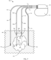
- FIG. 3 and FIG. 4 schematic diagrams of a subject 301 with a cancerous tumor 310 are shown in accordance to the embodiments herein.
- the subject 301 has a medical device 300 implanted entirely within the body of the subject 301 at or near the site of cancerous tumor 310.
- Various implant sites can be used including areas such as in the limbs, the upper torso, the abdominal area, the head, and the like.
- FIG. 3 schematic diagrams of a subject 301 with a cancerous tumor 310 are shown in accordance to the embodiments herein.
- the subject 301 has a medical device 300 implanted entirely within the body of the subject 301 at or near the site of cancerous tumor 310.
- Various implant sites can be used including areas such as in the limbs, the upper torso, the abdominal area, the head, and
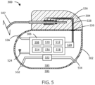
- the medical device 300 can include a housing 302 and a header 304 coupled to the housing 302, and medical device 400 can include a housing 302.
- the housing 302 can be formed of a material such as a metal, ceramic, polymer, composite, or the like.
- the housing 302, or one or more portions thereof, can be formed of titanium.
- the header 304 can be formed of various materials, but in some embodiments the header 304 can be formed of a translucent polymer such as an epoxy material. In some embodiments the header 304 can be hollow. In other embodiments the header 304 can be filled with components and/or structural materials such as epoxy or another material such that it is non-hollow.
- Header 304 can be coupled to one or more leads, such as leads 306.
- the header 304 can serve to provide fixation of the proximal end of one or more leads 306 and electrically couple the one or more leads 306 to one or more components within the housing 302.
- the one or more leads 306 can include one or more electrodes, such as electrodes 308, disposed along the length of the leads 306.
- electrodes 308 can include electric field generating electrodes, also referred to herein as "supply electrodes.”
- electrodes 308 can include electric field sensing electrodes, also referred to herein as "sensing electrodes.”.
- leads 306 can include both supply electrodes and sensing electrodes.
- control circuitry 506 can be configured to direct the electric field generating circuit 520 to deliver an electric field using a voltage falling within a range, wherein any of the forgoing voltages can serve as the lower or upper bound of the range, provided that the lower bound of the range is a value less than the upper bound of the range.
- the control circuitry of medical device 600 can be in communication with the electric field generating circuit, where the control circuitry is configured to control delivery of the one or more electric fields from the electric field generating circuit.
- the control circuitry can cause the electric field generating circuit to generate one or more electric fields having a field strength selected from a range of from 0.25 V/cm to 1000 V/cm.
- Medical device 600 can further generate one or more electric fields at various currents, frequencies, and/or voltages as described elsewhere herein.
- the first electric field strength can be selected from a range of about 0.1 V/cm to about 2 V/cm and the second electric field can be selected from a range of about 1 V/cm to about 100 V/cm.
- additional electric fields can also be used, such as, for example a third electric field, a fourth electric field, a fifth electric field, a sixth electric field, a seventh electric field, etc., where each electric field includes a corresponding electric field strength.
- Various electric field strengths suitable for use in the embodiments herein are described elsewhere herein.
- control circuitry can be configured to generate one or more electric fields by using a voltage control mode, where the voltage control mode includes modulating voltage in order to maintain a substantially constant electric field strength. In some embodiments, the control circuitry is configured to generate one or more electric fields by using a current control mode, where the current control mode includes modulating current in order to maintain a substantially constant electric field strength.
- At least one therapeutic parameter set can include modulating the one or more electric fields if the impedance at or near the site of the cancerous tumor changes by at least 5 %, changes by at least 15 %, or changes by at least 20 % during a given therapy relative to an initial impedance at or near the site of the cancerous tumor at a beginning of the given therapy.
- at least one therapeutic parameter set can include modulating the one or more electric fields if the impedance at or near the site of the cancerous tumor changes by at least 25 %, changes by at least 50 %, or changes by at least 75 % during a given therapy relative to an initial impedance at or near the site of the cancerous tumor at a beginning of the given therapy.
- the therapeutic parameter set can include modulating the one or more electric fields if the impedance at or near the site of the cancerous tumor changes by a percentage that is greater than or equal to 1 %, 2 %, 3 %, 5 %, 10 %, 15 %, 20 %, 25 %, 30 %, 35 %, 40%, 45%, 50 %, 55 %, 60 %, 65 %, 70 %, 75 %, 80 %, 85 %, 90 %, 95 %, 100 %, 150 %, 200 %, 300 %, 400 %, 500 %, 750 %, 1000 %, or more relative to an initial impedance at or near the site of the cancerous tumor, or can be an amount falling within a range between any of the foregoing.
- the therapeutic parameter set can include modulating the one or more electric fields if the impedance at or near the site of the cancerous tumor changes by a percentage that is greater than 100 % relative to an initial impedance at or near the site of the cancerous tumor.
- each electrode can be spatially separated along a longitudinal axis of the lead by at least 0.1, 0.2, 0.25, 0.3, 0.35, 0.4, 0.5, 0.75, 1, 2, 3, 4, 5, or 10 cm (or by an amount falling within a range between any of the foregoing).
- the first supply electrode 614 and the first sensing electrode 616 of the first lead 602 are spatially separated along a longitudinal axis of the first lead 602 by at least 0.25 cm; and the second supply electrode 618 and the second sensing electrode 620 of the second lead 608 are spatially separated along a longitudinal axis of the second lead 608 by at least 0.25 cm.
- the current flow through the first supply electrode 614 and second supply electrode 618 will not appreciably pass through the first sensing electrode pair, including the first sensing electrode 616 and second sensing electrode 620.
- the current flow through the first sensing electrode 616, the first sensing wire 606, the second sensing electrode 620, the second sensing wire 612, and components in electrical communication therewith is negligible.
- the current flow through the first sensing electrode 616, the first sensing wire 606, the second sensing electrode 620, the second sensing wire 612, and components in electrical communication therewith is less than 2000, 1000, 750, 500, 250, 100, 50, or 10 pA.
- the medical devices herein can include four leads, where a supply wire or a sensing wire can be present in separate leads, spatially separate from one another.
- FIG. 7 medical device 700 for treating a cancerous tumor 310 is shown in accordance with the embodiments herein.
- the medical device 700 can include a first lead 702 including a first supply wire 704, a second lead 706 including a first sensing wire 708, a third lead 710 including a second supply wire 712, and a fourth lead 714 including a second sensing wire 716.
- the first supply wire 704 and the second supply wire 712 can be configured as supply wires for supplying an electric field at or near the site of the cancerous tumor 310.
- the first sensing wire 708 and the second sensing wire 716 can be configured as sensing wires for measuring an impedance at or near the site of the cancerous tumor 310.
- the first lead 702 can include a first supply electrode 718 in electrical communication with the first supply wire 704.
- the second lead 706 can include a first sensing electrode 720 in electrical communication with the first sensing wire 708.
- the third lead 710 can include a second supply electrode 722 in electrical communication with the second supply wire 712.
- the fourth lead 714 can include a second sensing electrode 724 in electrical communication with the second sensing wire 716.
- the first supply electrode 718 and the second supply electrode 722 can be configured as a supply electrode pair to deliver an electric field at or near a site of the cancerous tumor 310.
- the first sensing electrode 720 and the second sensing electrode 724 can be configured as a sensing electrode pair to measure an impedance 624 of the cancerous tumor 310, where the impedance 624 is independent of an impedance of the first supply electrode 718, the first supply wire 704, the second supply electrode 722, the second supply wire 712, and any components in electrical communication therewith. In some embodiments, more than four leads and/or more than four wires can be used.
- the first supply electrode 718 and the second supply electrode 722 that form the first supply electrode pair can deliver an electric field along a first vector at or near the site of a cancerous tumor
- the first sensing electrode 720 and the second sensing electrode 724 that form the first sensing electrode pair can measure an impedance 624 of the cancerous tumor 310 along a second vector at or near the site of the cancerous tumor 310.
- the first vector and second vector can be spatially and or directionally separate from one another.
- the first vector and second vector can be spatially and or directionally separated (e.g., the vectors can be disposed at an angle with respect to one another) by at least about 10, 20, 30, 40, 50, 60, 70, 80 or 90 degrees.
- the first supply electrode pair can deliver an electric field at or near the site of a cancerous tumor along multiple vectors, and that the first sensing electrode pair can similarly measure impedance along multiple vectors that are spatially separate from the vector used to deliver the electric field.
- the sensing electrodes can be configured to sense an impedance 624 within a cancerous tumor along one or more vectors that are non-therapy vectors.
- the medical device 700 can also include additional sensing wires and additional sensing electrodes.
- second lead 706 can further include a third sensing wire 726 in electrical communication with a third sensing electrode 728 and fourth lead 714 can include a fourth sensing electrode 730 in electrical communication with a fourth sensing electrode 732.
- the third sensing electrode 728 and the fourth sensing electrode 730 can serve as a second sensing electrode pair that can be configured to sense an impedance 626 of the healthy tissue 601 surrounding the cancerous tumor 310, but not the impedance 624 of the cancerous tumor itself.
- the medical devices herein can include additional configurations using multiple supply wires and multiple supply electrodes to deliver an electric field at or near the site of a cancerous tumor, and multiple sensing wires and multiple sensing electrodes to measure impedance within a cancerous tumor or a health tissue.
- the medical devices can include both internal and external components.
- FIG. 8 a schematic diagram of a medical device 800 is shown in accordance with the embodiments herein.
- Medical device 800 can include an internal portion at the internal side 850 of the subject's body and an external portion at the external side 852 of the subject's body.
- the internal portion of medical device 800 can include internal electric lead 801 and the external portion can include the housing 302 and the external electric lead 802.
- the medical device 800 can also include a transcutaneous access port 820 spanning the exterior surface 822 of the subject's body at or near the site of the cancerous tumor 310 suitable to receive one or more leads or catheters.
- transcutaneous access port 820 can be configured to receive at least one of the internal electric lead 801, a drug delivery catheter for delivery of one or more chemotherapeutic agents, an optical lead including one or more optical emitters for delivering optical energy, a biopsy apparatus for obtaining a biopsy sample from the cancerous tumor, or an irrigation catheter for flushing the site of the cancerous tumor of waste products or bodily fluids.
- Internal electric lead 801 can include one or more electrodes such as sensing electrodes 804 and 808, and supply electrodes 806 and 810 disposed along the length of internal electric lead 801.
- External electric lead 802 can include sensing electrodes 812 and 816, and supply electrodes 814 and 818 disposed along the length of the external electric lead 802.
- electrodes 804, 806, 808, 810, 812, 814, 816, and 818 can include any configuration of electric field generating electrodes and electric field sensing electrodes.
- internal electric lead 801 or external electric lead 802 can include both electric field generating and electric field sensing electrodes in any configuration. It will be appreciated that while not shown in FIG. 8 , each supply electrode and each sensing electrode has associated therewith a wire in electrical communication with the electric field generating circuit.
- the proximal ends of internal electric lead 801 or external electric lead 802 are disposed within the housing 302.
- the distal ends of internal electric lead 801 can surround a cancerous tumor 310 such that the electrodes 804, 806, 808, and 810 are brought into proximity of the cancerous tumor 310.
- External electric lead 802 can be placed on the exterior of the subject's body near the site of the cancerous tumor such that the electrodes 812, 814, 816, and 818 are in electrical communication with electrodes 804, 806, 808, and 810 on internal electric lead 801.
- the internal electric lead 801 can be positioned within the vasculature such that electrodes 804, 806, 808, and 810 are adjacent to or positioned within the cancerous tumor 310.
- internal electric lead 801 can be disposed in various places within or around the cancerous tumor 310.
- the internal electric lead 801 can pass directly through the cancerous tumor 310.
- the internal electric lead 801 can include one or more tracking markers 826 along the length of the internal electric lead 801 for use in determining the precise location of the electrodes relative to the tumor.
- the one or more tracking markers can be disposed directly distal or directly proximal to the one or more electrodes disposed on the internal electric lead 801.
- the tracking markers can be formed from a magnetic material.
- the tracking markers can be formed from a radiographic material.
- the tracking markers can be formed from a fluorographic material.
- a plurality of electric field vectors can be generated between various combinations of supply electrodes 806, 810, 814, or 818 disposed along internal electric lead 801 and external electric lead 802 to create an electric field.
- one or more electric field vectors can be generated between supply electrodes 806 and 814.
- one or more electric field vectors can be generated between supply electrodes 810 and 818.
- one or more electric field vectors can be generated between any combination of supply electrodes 806, 810, 814, or 818.
- one or more electric field vectors can be generated between any combination of supply electrodes 806, 810, 814, or 818 and the housing 302 of medical device 800.
- sensing electrodes 804, 808, 812, and 816 can sense an impedance 624 within the cancerous tumor 310 along one or more vectors between any combination of sensing electrodes 804, 808, 812, and 816, where sensing an impedance 624 of a cancerous tumor 310 can be independent of any impedance present in any of supply electrodes 806, 810, 814, or 818 or any wires or components in electrical communication therewith. It will be further appreciated that sensing electrodes 804, 808, 812, and 816 can sense an impedance 626 within the healthy tissue 601 surrounding the cancerous tumor 310 along one or more vectors between any combination of sensing electrodes 804, 808, 812, and 816.
- Sensing an impedance 626 of a healthy tissue 601 can be independent of any impedance present in cancerous tumor 310 or any of the supply electrodes 806, 810, 814, or 818 or any wires or components in electrical communication therewith. Sensing an impedance 626 of a healthy tissue 601 can be performed along one or more non-therapy vectors between any of the sensing electrodes 804, 808, 812, and 816.
- sensing electrodes can sense an impedance 824 of any of the supply electrodes along one or more vectors between any combination of sensing electrodes 804, 808, 812, and 816 and the supply electrodes 806, 810, 814, or 818.
- the sensing electrodes 804, 808, 812, and 816 can sense an impedance 824 of any of the supply electrodes along one or more non-therapy vectors.
- Each sensing electrode can be further configured to measure impedance of any of the supply electrodes 806, 810, 814, or 818 independent of an impedance produced by the cancerous tumor 310 or any of the other supply electrodes, leads, wires and any components in electrical communication therewith.
- the supply electrodes 806, 810, 814, or 818 can perform unipolar impedance measurements to differentiate the impedance of each supply electrode.
- a coating 860 including an active agent or drug can be disposed over a portion of the outside surface of the lead 801 body or shaft of an implanted portion of the lead 801 (which could partially be implanted as shown in FIG. 8 or fully implanted as shown in FIGS. 6-7 ).
- the coating 860 can be a drug-eluting coating.
- the portion of the lead 801 covered by the coating 860 can be about 0.1, 0.5, 1, 1.5, 2, 3, 5, 7.5, 10, 15, 20, 40, 60, or 80 centimeters in length.
- the coating 860 can fully surround the lead 801 forming a ring of coating 360 degrees around the lead 801.
- the cytotoxic agent can be useful, particularly for leads that will be immediately adjacent to or even within a cancerous tumor in order to prevent the migration of cancerous cells away from the tumor site using the lead as a pathway.
- a cytotoxic agent coating can be placed at a point in between the proximal end of the lead and the site of the tumor.
- a “unipolar” impedance measurement refers to the scenario where the housing (or case or can) of the implanted device itself serves as one of the two electrodes in the pair required for passing a current in order to measure voltage drop and derive impedance.
- a “bipolar” impedance measurement refers to the scenario where the housing (or case or can) of the implanted device itself does not serve as one of the two electrodes in the pair required for passing a current in order to measure voltage drop and derive impedance (e.g., the two electrodes are disposed on leads or other structures external to the housing of implanted device).
- the various impedance measurements herein can be unipolar impedance measurements, while in other embodiments the various impedance measurements herein can be bipolar impedance measurements.
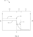
- an exemplary plot 900 of the dielectric relaxation of a biological tissue is shown in accordance with various embodiments herein.
- An electric field, E can be applied to a biological tissue, such as a cancerous tumor or a healthy tissue, for a predetermined time, t. During application of the electric field, the biological tissue can become polarized within the electric field, as discussed elsewhere herein.
- a plot of the electric field, E, as a function of time is shown as plot 902.
- a plot of the polarization, P, of the biological tissue as a function of time is shown as plot 906.
- a constant electric field, E can be applied to the biological tissue for a predetermined period of time 908.
- the channel interfaces 1006, 1010, and 1014 can include various components such as analog-to-digital converters for digitizing signal inputs, sensing amplifiers, registers which can be written to by the control circuitry in order to adjust the gain and threshold values for the sensing amplifiers, source drivers, modulators, demodulators, multiplexers, and the like.
- the physiological sensors can include sensors that monitor temperature, blood flow, blood pressure, and the like.
- the respiration sensors can include sensors that monitor respiration rate, respiration peak amplitude, and the like.
- the chemical sensors can measure the quantity of an analyte present in a treatment area about the sensor, including but not limited to analytes such as of blood urea nitrogen, creatinine, fibrin, fibrinogen, immunoglobulins, deoxyribonucleic acids, ribonucleic acids, potassium, sodium, chloride, calcium, magnesium, lithium, hydronium, hydrogen phosphate, bicarbonate, and the like. However, many other analytes are also contemplated herein. Exemplary chemical/analyte sensors are disclosed in commonly owned U.S. Pat. No. 7,809,441 to Kane et al. , and which is hereby incorporated by reference in its entirety.
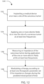
- Method 1100 can include implanting a medical device at or near a site of the cancerous tumor at 1102.
- the method 1100 can include applying at least two electric fields at or near the site of the cancerous tumor to deliver at least a first electric field having a first electric field strength and a second electric field having a second electric field strength at 1104.
- Applying the one or more electric fields can include using one or more supply leads where each can include one or more supply electrodes.
- the method 1100 can include measuring an impedance of the cancerous tumor at the at least two electric field strengths at 1106. Measuring an impedance can include using one or more sensing leads that each include one or more sensing electrodes.
- the method 1100 can include modulating a therapy according to at least one therapeutic parameter set if the impedance changes at 1108.
- the method 1200 can include measuring an impedance of the cancerous tumor during application of the one or more electric fields at the at least two frequencies at 1206. Measuring an impedance can include using one or more sensing leads that can include one or more sensing electrodes.
- the method 1200 can include modulating the therapy according to the at least one therapeutic parameter set if the impedance changes during the predetermined period of time at 1208. In some embodiments, method 1200 can include sweeping from a first frequency up to a second frequency and sweeping from the second frequency down to the first frequency is repeated throughout the duration of the generating the one or more electric fields with the electric field generating circuit.
- the method 1300 can include implanting a medical device at or near a site of the cancerous tumor at 1302.
- the method 1300 can include applying one or more electric fields at or near the site of the cancerous tumor to deliver a therapy according to at least one therapeutic parameter set for a predetermined period of time at 1304.
- Applying the one or more electric fields can include using one or more supply leads, where each can include one or more supply electrodes.
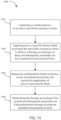
- the method 1300 can include measuring an impedance of the cancerous tumor at predetermined intervals during application of one or more electric fields during the predetermined period of time at 1306.
- At least method 1100, method 1200, or method 1300 can include modulating the therapy according to the at least one therapeutic parameter set by modulating the one or more electric fields if the impedance at or near the site of the cancerous tumor changes by at least 25 %, changes by at least 50 %, or changes by at least 75% during a given therapy relative to an initial impedance at or near the site of the cancerous tumor at a beginning of the given therapy.
- modulating the therapy according to the at least one therapeutic parameter set can include modulating the one or more electric fields if the impedance at or near the site of the cancerous tumor changes by a percentage that is greater than 100 % relative to an initial impedance at or near the site of the cancerous tumor.
- Measuring a polarization of the cancerous tumor can include using one or more sensing leads that can include one or more sensing electrodes.
- the method can include modulating the therapy according to the at least one therapeutic parameter set if the polarization of the cancerous tumor changes during the predetermined period of time at 1508.
- At least method 1400 and method 1500 can include modulating the therapy according to the at least one therapeutic parameter set includes modulating the one or more electric fields if the polarization at or near the site of the cancerous tumor changes by at least 25 %, changes by at least 50 %, or changes by at least 75% during a given therapy relative to an initial polarization at or near the site of the cancerous tumor at a beginning of the given therapy.
- At least method 1400 and method 1500 can include modulating the therapy according to the at least one therapeutic parameter set includes modulating the one or more electric fields if the polarization at or near the site of the cancerous tumor changes by at least 5 %, changes by at least 15 %, or changes by at least 20 % during a given therapy relative to an initial polarization at or near the site of the cancerous tumor at a beginning of the given therapy.
- applying the one or more electric fields can include at least applying an electric field at various frequencies.
- the one or more electric fields can be applied to the cancerous tumor at frequencies selected from a range within 10 kilohertz (kHz) to 1 megahertz (MHz).
- the one or more electric fields can be applied to the cancerous tumor at frequencies selected from a range within 300 kHz to 500 kHz.
- the one or more electric fields can be applied to the cancerous tumor at frequencies selected from a range within 100 kHz to 300 kHz.
- the frequency of the one or more applied electric fields can be greater than or equal to 10 kHz, 20 kHz, 30 kHz, 40 kHz, 50 kHz, 60 kHz, 70 kHz, 80 kHz, 90 kHz, 300 kHz, 125 kHz, 150 kHz, 175 kHz, 400 kHz, 225 kHz, 250 kHz, 275 kHz, 300 kHz, 325 kHz, 350 kHz, 375 kHz, 400 kHz, 425 kHz, 450 kHz, 475 kHz, 500 kHz, 525 kHz, 550 kHz, 575 kHz, 600 kHz, 625 kHz, 650 kHz, 675 kHz, 700 kHz, 725 kHz, 750 kHz, 775 kHz, 800 kHz, 825 kHz, 850 kHz, 875 kHz, 900 kHz,
- applying the one or more electric fields can include at least applying an electric field for various predetermined time periods.
- the one or more electric fields can be applied at or near the site of the cancerous tumor over a predetermined time period selected from a range of predetermined time periods from 1 minute to 24 hours.
- the one or more electric fields can be applied at or near the site of the cancerous tumor over a predetermined time period can be greater than or equal to 1, 10, 20, 30, 40, or 50 minutes, or 1.0, 1.5, 2.0, 2.5, 3.0, 3.5, 4.0, 4.5, 5.0, 5.5, 6.0, 6.5, 7.0, 7.5, 8.0, 8.5, 9.0, 9.5, 10.0, 10.5, 11.0, 11.5, 12.0, 12.5, 13.0, 13.5, 14.0, 14.5, 15.0, 15.5, 16.0, 16.5, 17.0, 17.5, 18.0, 18.5, 19.0, 19.5, 20.0, 20.5, 21.0, 21.5, 22.0, 22.5, 23.0, 23.5, 24.0, or 48 hours, or can be an amount falling in a range within any of the foregoing.
- administering a chemotherapeutic agent can include administering the chemotherapeutic agent for various predetermined time periods.
- the chemotherapeutic agent can be administered at or near the site of the cancerous tumor over a predetermined time period selected from a range of predetermined time periods from less than 1 minute to 600 minutes.
- applying the one or more electric fields at or near the site of the cancerous tumor can include applying the one or more electric fields to the exterior or interior of the subject. In some embodiments, applying the one or more electric fields to the cancerous tumor can include applying the one or more electric fields entirely to the exterior of the subject at or near the site of the cancerous tumor. In some embodiments, applying the one or more electric fields to the cancerous tumor can include applying the one or more electric fields entirely to the interior of the subject at or near the site of the cancerous tumor. In some embodiments, applying the one or more electric fields to the cancerous tumor can include applying the one or more electric fields at least partially to the exterior of the subject at or near the site of the cancerous tumor.
- administering an electric field to the cancerous tumor can change based on the measured impedance.
- impedance within a cancerous tumor is relatively low when compared to non-cancerous or necrotic tissue. This phenomenon allows impedance to be monitored as a function of therapy duration and to serve as a diagnostic tool in assessing whether or not a tumor is responding to an electric field therapy. If the impedance within a treatment area increases (across a fixed distance or area as a result of the low-impedance tumor tissue shrinking and non-cancerous tissue occupying the remaining space) then this can be taken as an indication that the electric field therapy is effectively decreasing the size of the cancerous tumor.
- the therapeutic parameter sets can be programmed into a medical device to operate autonomously, or they can be queried and manipulated by the subject or a clinician using an external computation device such as a programmer, a home-based unit, and/or a mobile unit (e.g. a cellular phone, personal computer, smart phone, tablet computer, and the like).
- the therapeutic parameter sets can be wirelessly communicated to the medical device from an external computation device. Frequencies and/or electric field strengths suitable for use in any of the therapeutic parameter sets herein are discussed above with respect to electric field generating circuit.
- one or more therapeutic parameter sets can be implemented simultaneously.
- one or more therapeutic parameter sets can be implemented in an alternating fashion.
- the one or more electric fields can be effective to prevent and/or disrupt cellular mitosis in a cancerous cell.
- the natural body orifice can include any of the nasal passages, the ear canal, the mouth, the esophagus, the trachea, the urethra, the vagina, the small intestine, the anus, or the colon.
- a suitable duct can include those accessible via the gastrointestinal or genitourinary systems, including the common bile duct, the bile duct, the pancreatic duct, the common hepatic duct, the ureters, the Eustachian tubes, or the fallopian tubes.
- the leads can be placed adjacent to or within a cancerous tumor. In some embodiments, multiple leads can be used near to or far from the cancerous tumor.
- one or more leads described herein can be placed in the subcutaneous space. Electrodes on leads placed in the subcutaneous space can be used as the primary near-field generating electrode or as a far-field field generating electrode. In some embodiments, electrodes on leads placed in the subcutaneous space can be used as the primary near-field generating electrode or as a far-field field generating electrode in conjunction with the housing of a medical device. Likewise, one or more leads can be placed transvascularly to act as far-field field generating electrodes in conjunction with an electrode at or near the site of the cancerous tumor or in conjunction with the housing of a medical device.
- the LEDs suitable for use herein can include an LED capable of emitting only one color, or a mono-color LED; an LED capable of emitting two colors, or a bi-color LED; an LED capable of emitting three colors, or a tri-color LED; or an LED capable of emitting more than three colors.
- the LEDs can be in electrical communication with control circuitry within the housing of the medical devices described herein.
- one or more laser diodes can be included along the leads herein, and the laser diodes can be in optical communication with one or more optical fibers disposed within the leads and used for transmitting light from a laser source to a laser diode.
- the first electric field strength is selected from a range of from 0.1 V/cm to 2 V/cm and the second electric field strength is selected from a range of from 1 V/cm to 100 V/cm.
- control circuitry is further configured to implement the one or more therapeutic parameter sets to deliver a given therapy.
- control circuitry is configured to modulate the one or more electric fields if the impedance at or near the site of the cancerous tumor changes by at least 5 % during a therapy relative to an initial impedance at or near the site of the cancerous tumor at a beginning of the given therapy.
- the one or more electric fields is modulated by increasing or decreasing the electric field strength.
- control circuitry causes the electric field generating circuit to generate the one or more electric fields at frequencies selected from a range of from 10 kHz to 1 MHz at or near a site of the cancerous tumor.
- control circuitry is further configured to generate one or more electric fields by sweeping through a range of frequencies, wherein sweeping through a range of frequencies includes sweeping from a first frequency up to a second frequency and sweeping from the second frequency down to the first frequency, wherein the second frequency is higher than the first frequency.
- the range of frequencies includes a range of frequencies of from 100 kHz to 500 kHz.
- the therapeutic coating is a cytotoxic coating.
- the medical device is configured to be partially implanted within a subject.
- control circuitry is further configured to generate one or more electric fields by sweeping through a range of frequencies, wherein sweeping through a range of frequencies includes sweeping from a first frequency up to a second frequency and sweeping from the second frequency down to the first frequency, wherein the second frequency is higher than the first frequency.
- the range of frequencies includes a range of frequencies of from 10 kHz to 1 MHz. In an embodiment, the range of frequencies includes a range of frequencies of from 100 kHz to 500 kHz. In an embodiment, the range of frequencies includes a range of frequencies of from 300 kHz to 500 kHz.
- the at least one therapeutic parameter set further includes modulating the one or more electric fields by increasing or decreasing a strength of the one or more electric fields.
- modulating the therapy according to the at least one therapeutic parameter set includes modulating the one or more electric fields if the impedance at or near the site of the cancerous tumor changes by at least 50 % during a therapy relative to an initial impedance measured at or near the site of the cancerous tumor at a beginning of the therapy.
- modulating the therapy according to the at least one therapeutic parameter set includes terminating the at least one therapeutic parameter set if the impedance falls outside of a predetermined range during the predetermined period of time.
- the one or more electric fields includes a field strength selected from a range of from 0.25 V/cm to 1000 V/cm.
- the medical device is implanted entirely within a subject.
- the medical device is partially implanted within a subject.
- the first frequency is less than the second frequency.
- the first frequency is selected from a range of 10 kHz to 500 kHz and the second frequency is selected from a range of 501 kHz to 1 MHz.
- the first electric field has a first electric field strength and the second electric field has a second electric field strength.
- the first electric field strength is the same as the second electric field strength.
- modulating the therapy according to the at least one therapeutic parameter set includes modulating the one or more electric fields if the impedance at or near the site of the cancerous tumor changes by at least 25 % during a therapy relative to an initial impedance measured at or near the site of the cancerous tumor at a beginning of the therapy.
- the at least one therapeutic parameter set further includes modulating the one or more electric fields by increasing or decreasing a strength of the one or more electric fields.
- modulating the therapy according to the at least one therapeutic parameter set includes terminating the at least one therapeutic parameter set if the impedance falls outside of a predetermined range during the predetermined period of time.
- the at least one therapeutic parameter set further includes modulating the one or more DC electric fields by increasing or decreasing a strength of the one or more DC electric fields.
- modulating the therapy according to the at least one therapeutic parameter set includes terminating the at least one therapeutic parameter set if the polarization falls outside of a predetermined range during the predetermined period of time.
Landscapes
- Health & Medical Sciences (AREA)
- Life Sciences & Earth Sciences (AREA)
- Engineering & Computer Science (AREA)
- Biomedical Technology (AREA)
- Nuclear Medicine, Radiotherapy & Molecular Imaging (AREA)
- Radiology & Medical Imaging (AREA)
- Animal Behavior & Ethology (AREA)
- General Health & Medical Sciences (AREA)
- Public Health (AREA)
- Veterinary Medicine (AREA)
- Hospice & Palliative Care (AREA)
- Oncology (AREA)
- Cardiology (AREA)
- Heart & Thoracic Surgery (AREA)
- Biophysics (AREA)
- Physiology (AREA)
- Neurology (AREA)
- Neurosurgery (AREA)
- Electrotherapy Devices (AREA)
- Measurement And Recording Of Electrical Phenomena And Electrical Characteristics Of The Living Body (AREA)
Applications Claiming Priority (3)
| Application Number | Priority Date | Filing Date | Title |
|---|---|---|---|
| US201962837128P | 2019-04-22 | 2019-04-22 | |
| PCT/US2020/028509 WO2020219337A1 (en) | 2019-04-22 | 2020-04-16 | Systems for administering electrical stimulation to treat cancer |
| EP20724333.8A EP3958959B1 (de) | 2019-04-22 | 2020-04-16 | Vorrichtungen zur verabreichung einer elektrischen stimulation zur behandlung von krebs |
Related Parent Applications (1)
| Application Number | Title | Priority Date | Filing Date |
|---|---|---|---|
| EP20724333.8A Division EP3958959B1 (de) | 2019-04-22 | 2020-04-16 | Vorrichtungen zur verabreichung einer elektrischen stimulation zur behandlung von krebs |
Publications (3)
| Publication Number | Publication Date |
|---|---|
| EP4397361A2 true EP4397361A2 (de) | 2024-07-10 |
| EP4397361A3 EP4397361A3 (de) | 2024-08-28 |
| EP4397361B1 EP4397361B1 (de) | 2025-11-05 |
Family
ID=70554246
Family Applications (2)
| Application Number | Title | Priority Date | Filing Date |
|---|---|---|---|
| EP24171875.8A Active EP4397361B1 (de) | 2019-04-22 | 2020-04-16 | Vorrichtungen zur verabreichung elektrischer stimulation zur behandlung von krebs |
| EP20724333.8A Active EP3958959B1 (de) | 2019-04-22 | 2020-04-16 | Vorrichtungen zur verabreichung einer elektrischen stimulation zur behandlung von krebs |
Family Applications After (1)
| Application Number | Title | Priority Date | Filing Date |
|---|---|---|---|
| EP20724333.8A Active EP3958959B1 (de) | 2019-04-22 | 2020-04-16 | Vorrichtungen zur verabreichung einer elektrischen stimulation zur behandlung von krebs |
Country Status (5)
| Country | Link |
|---|---|
| US (1) | US11420049B2 (de) |
| EP (2) | EP4397361B1 (de) |
| JP (1) | JP7410176B2 (de) |
| CN (1) | CN113766949B (de) |
| WO (1) | WO2020219337A1 (de) |
Families Citing this family (18)
| Publication number | Priority date | Publication date | Assignee | Title |
|---|---|---|---|---|
| US11338135B2 (en) | 2017-10-23 | 2022-05-24 | Cardiac Pacemakers, Inc. | Medical devices for cancer therapy with electric field shaping elements |
| US12403306B2 (en) | 2017-10-23 | 2025-09-02 | Cardiac Pacemakers, Inc. | Electric field shaping leads for treatment of cancer |
| JP2022522936A (ja) | 2019-02-27 | 2022-04-21 | ノボキュア ゲーエムベーハー | 埋込可能な変換器アレイを使用した腫瘍治療電場(ttfields)の送達 |
| US12109412B2 (en) | 2019-04-22 | 2024-10-08 | Boston Scientific Scimed, Inc. | Combination electrical and chemotherapeutic treatment of cancer |
| CN113727753B (zh) | 2019-04-22 | 2024-09-13 | 波士顿科学国际有限公司 | 用于癌症治疗的电刺激装置 |
| WO2020219337A1 (en) | 2019-04-22 | 2020-10-29 | Boston Scientific Scimed, Inc. | Systems for administering electrical stimulation to treat cancer |
| WO2020219519A1 (en) | 2019-04-23 | 2020-10-29 | Boston Scientific Scimed, Inc. | Electrodes for electrical stimulation to treat cancer |
| US11712561B2 (en) | 2019-04-23 | 2023-08-01 | Boston Scientific Scimed, Inc. | Electrical stimulation with thermal treatment or thermal monitoring |
| US11607542B2 (en) | 2019-04-23 | 2023-03-21 | Boston Scientific Scimed, Inc. | Electrical stimulation for cancer treatment with internal and external electrodes |
| US20210199640A1 (en) * | 2019-12-26 | 2021-07-01 | The Board of Trustees of the Leland Stanford Junior Unviersity | Methods of Normalizing Aberrant Glycolytic Metabolism in Cancer Cells |
| CN115515674A (zh) | 2020-02-24 | 2022-12-23 | 波士顿科学国际有限公司 | 用于治疗胰腺癌的系统和方法 |
| WO2022147153A1 (en) * | 2020-12-30 | 2022-07-07 | Novocure Gmbh | Amplitude modulation for tumor treating fields |
| US12161876B2 (en) * | 2020-12-30 | 2024-12-10 | Novocure Gmbh | Amplitude modulation for tumor treating fields |
| KR102650606B1 (ko) * | 2021-10-15 | 2024-03-21 | 가톨릭대학교 산학협력단 | 암치료용 전류 공급 방법 및 장치 |
| US20230149708A1 (en) * | 2021-11-12 | 2023-05-18 | University Of South Carolina | Tumor treating fields (ttf) for cancer treatment |
| GB2631521A (en) * | 2023-07-05 | 2025-01-08 | Qv Bioelectronics Ltd | Electric field therapy |
| US20250073462A1 (en) * | 2023-08-30 | 2025-03-06 | Mayo Foundation For Medical Education And Research | Implantable medical systems for cancer treatment with activation energy based therapy modulation |
| CN117982802B (zh) * | 2024-04-07 | 2024-06-18 | 浙江大学 | 一种闭环肺部肿瘤电场治疗系统 |
Citations (1)
| Publication number | Priority date | Publication date | Assignee | Title |
|---|---|---|---|---|
| US7809441B2 (en) | 2006-05-17 | 2010-10-05 | Cardiac Pacemakers, Inc. | Implantable medical device with chemical sensor and related methods |
Family Cites Families (126)
| Publication number | Priority date | Publication date | Assignee | Title |
|---|---|---|---|---|
| US4016886A (en) | 1974-11-26 | 1977-04-12 | The United States Of America As Represented By The United States Energy Research And Development Administration | Method for localizing heating in tumor tissue |
| US5397342A (en) | 1993-06-07 | 1995-03-14 | Cardiac Pacemakers, Inc. | Resilient structurally coupled and electrically independent electrodes |
| US5582609A (en) | 1993-10-14 | 1996-12-10 | Ep Technologies, Inc. | Systems and methods for forming large lesions in body tissue using curvilinear electrode elements |
| US5458597A (en) | 1993-11-08 | 1995-10-17 | Zomed International | Device for treating cancer and non-malignant tumors and methods |
| DE69521308T2 (de) | 1994-04-01 | 2002-05-02 | Akzo Nobel N.V., Arnheim/Arnhem | Verwendung eines sicherheitsklemmens zur abdichtung von behältern für chemische verbindungen, und ein behälter dafür |
| US5755758A (en) | 1995-11-07 | 1998-05-26 | Medtronic, Inc. | Intramuscular stimulation lead with enhanced infection resistance |
| US6366808B1 (en) | 2000-03-13 | 2002-04-02 | Edward A. Schroeppel | Implantable device and method for the electrical treatment of cancer |
| US6549812B1 (en) | 1999-11-29 | 2003-04-15 | Medtronic, Inc. | Medical electrical lead having bending stiffness which increase in the distal direction |
| GB0002849D0 (en) | 2000-02-08 | 2000-03-29 | Gyrus Medical Ltd | An electrosurgical instrument and an electosurgery system including such an instrument |
| US7146210B2 (en) | 2000-02-17 | 2006-12-05 | Standen Ltd. | Apparatus and method for optimizing tumor treatment efficiency by electric fields |
| US7136699B2 (en) * | 2002-10-02 | 2006-11-14 | Standen, Ltd. | Apparatus for destroying dividing cells |
| US7805201B2 (en) | 2000-02-17 | 2010-09-28 | Standen Ltd. | Treating a tumor or the like with an electric field |
| US8175698B2 (en) | 2000-02-17 | 2012-05-08 | Novocure Ltd. | Treating bacteria with electric fields |
| US6868289B2 (en) | 2002-10-02 | 2005-03-15 | Standen Ltd. | Apparatus for treating a tumor or the like and articles incorporating the apparatus for treatment of the tumor |
| US8447395B2 (en) | 2000-02-17 | 2013-05-21 | Novocure Ltd | Treating bacteria with electric fields |
| US7089054B2 (en) | 2002-10-02 | 2006-08-08 | Standen Ltd. | Apparatus and method for treating a tumor or the like |
| CN1416466A (zh) | 2000-02-17 | 2003-05-07 | 约朗姆·帕尔蒂 | 破坏正在分裂的细胞的方法和装置 |
| US8024048B2 (en) * | 2000-03-13 | 2011-09-20 | Ionix Medical Inc. | Method and device for treating cancer with electrical therapy in conjunction with chemotherapeutic agents and radiation therapy |
| US6673623B1 (en) | 2000-09-12 | 2004-01-06 | Novocure, Inc. | Methods and compositions that control lipid production |
| WO2002083016A1 (en) | 2001-04-13 | 2002-10-24 | Surgi-Vision, Inc. | Systems and methods for magnetic-resonance-guided interventional procedures |
| US20020198567A1 (en) | 2001-06-07 | 2002-12-26 | Yona Keisari | Electro-endocytotic therapy as a treatment modality of cancer |
| JP2003036987A (ja) | 2001-07-24 | 2003-02-07 | Harison Toshiba Lighting Corp | 放電ランプ点灯装置、機器および画像形成装置 |
| US6909918B2 (en) | 2001-10-10 | 2005-06-21 | Medtronic, Inc. | Implantable percutaneous stimulation lead with lead carrier |
| US7653438B2 (en) | 2002-04-08 | 2010-01-26 | Ardian, Inc. | Methods and apparatus for renal neuromodulation |
| US20030204161A1 (en) | 2002-04-25 | 2003-10-30 | Bozidar Ferek-Petric | Implantable electroporation therapy device and method for using same |
| AU2003299471A1 (en) | 2002-05-07 | 2004-05-13 | Kai Kroll | Method and device for treating concer with electrical therapy in conjunction with chemotherapeutic agents and radiation therapy |
| DE10255858A1 (de) | 2002-11-29 | 2004-06-17 | Evotec Oai Ag | Fluidisches Mikrosystem mit feldformenden Passivierungsschichten auf Mikroelektroden |
| US8500713B2 (en) * | 2003-10-29 | 2013-08-06 | Medtronic, Inc. | Implantable electroporation therapy device and method for using same |
| US20050222646A1 (en) | 2004-04-06 | 2005-10-06 | Kai Kroll | Method and device for treating cancer with modified output electrical therapy |
| US7720549B2 (en) | 2004-04-06 | 2010-05-18 | Oncostim, Inc. | Partially implantable system for the electrical treatment of abnormal tissue growth |
| CA2586802A1 (en) | 2004-11-08 | 2006-05-11 | Continence Control Systems International Pty Ltd. | An implantable electrode arrangement |
| AU2005301103A1 (en) | 2004-11-08 | 2006-05-11 | Continence Control Systems International Pty Ltd | An implantable electrode arrangement |
| US8409111B2 (en) | 2004-11-22 | 2013-04-02 | Bard Peripheral Vascular, Inc. | Removable localizing wire |
| DE602005020504D1 (de) | 2004-12-07 | 2010-05-20 | Standen Ltd | Vivo über einen längeren zeitraum |
| DK1899001T3 (en) | 2005-06-08 | 2017-12-04 | Novocure Ltd | DEVICE FOR CANCER TREATMENT WITH ELECTRIC FIELDS MADE FOR DESIRED LOCATIONS IN A BODY |
| JP5249024B2 (ja) | 2005-06-28 | 2013-07-31 | バイオネス インコーポレイテッド | 電流を通す埋込み受動導体を使用するインプラント、システムおよび方法に対する改良 |
| CN101321555B (zh) | 2005-10-03 | 2020-12-08 | 诺沃库勒有限责任公司 | 优化电场特征以增加电场在增殖细胞上的效果 |
| US8019414B2 (en) | 2006-04-05 | 2011-09-13 | Novocure Ltd. | Treating cancer using electromagnetic fields in combination with other treatment regimens |
| US7899555B2 (en) | 2006-04-11 | 2011-03-01 | Pacesetter, Inc. | Intrapericardial lead |
| JP5457183B2 (ja) | 2006-09-14 | 2014-04-02 | ラジュール・テクノロジーズ・エルエルシイ | 癌細胞を破壊する装置及び方法 |
| US8002821B2 (en) | 2006-09-18 | 2011-08-23 | Boston Scientific Scimed, Inc. | Bioerodible metallic ENDOPROSTHESES |
| US8728073B2 (en) | 2006-10-10 | 2014-05-20 | Biosense Webster, Inc. | Multi-region staged inflation balloon |
| US20080183248A1 (en) | 2007-01-17 | 2008-07-31 | The Cleveland Clinic Foundation | Apparatus and methods for treating pulmonary conditions |
| US7937147B2 (en) | 2007-02-28 | 2011-05-03 | Cardiac Pacemakers, Inc. | High frequency stimulation for treatment of atrial fibrillation |
| DK2167194T3 (en) | 2007-03-06 | 2017-06-19 | Novocure Ltd | TREATMENT OF CANCER USING ELECTROMAGNETIC FIELDS IN COMBINATION WITH PHOTODYNAMIC THERAPY |
| US8376013B2 (en) | 2008-03-11 | 2013-02-19 | Duke University | Plasmonic assisted systems and methods for interior energy-activation from an exterior source |
| EP2183024B1 (de) | 2007-08-14 | 2019-05-15 | Novocure Ltd. | Behandlung von parasiten mit elektrischen feldern |
| WO2009036457A1 (en) | 2007-09-14 | 2009-03-19 | Lazure Technologies, Llc | Multi-layer electrode ablation probe and related methods |
| WO2009036459A1 (en) | 2007-09-14 | 2009-03-19 | Lazure Technologies, Llc | Multi-tine probe and treatment by activation of opposing tines |
| US8715203B2 (en) | 2007-09-17 | 2014-05-06 | Novocure Limited | Composite electrode |
| TWI348280B (en) | 2008-01-21 | 2011-09-01 | Univ Nat Taiwan | Dual injection locked frequency dividing circuit |
| US8968173B2 (en) * | 2008-07-16 | 2015-03-03 | Frank Sivo | Methods to arrest cancer cell growth and proliferation using electromagnetic energy delivered via electromagnetic coil systems |
| US8886334B2 (en) | 2008-10-07 | 2014-11-11 | Mc10, Inc. | Systems, methods, and devices using stretchable or flexible electronics for medical applications |
| WO2010118387A1 (en) | 2009-04-09 | 2010-10-14 | Virginia Tech Intellectual Properties, Inc. | Integration of very short electric pulses for minimally to noninvasive electroporation |
| TWI423738B (zh) | 2009-04-28 | 2014-01-11 | Masayuki Kumada | A method and apparatus for generating high density hollow electron cloud instantaneously by laser |
| WO2010126877A1 (en) | 2009-04-30 | 2010-11-04 | Medtronic, Inc. | Shielding an implantable medical lead |
| US8340783B2 (en) | 2009-06-30 | 2012-12-25 | Medtronic, Inc. | Implantable medical device lead with selectively exposed electrodes and reinforcement member |
| CN101693875B (zh) | 2009-09-30 | 2012-04-18 | 重庆大学 | 基于柱状微电极阵列的细胞电融合芯片装置及电融合方法 |
| WO2011112773A2 (en) | 2010-03-11 | 2011-09-15 | Mainstay Medical, Inc. | Modular stimulator for treatment of back pain, implantable rf ablation system and methods of use |
| US9526911B1 (en) | 2010-04-27 | 2016-12-27 | Lazure Scientific, Inc. | Immune mediated cancer cell destruction, systems and methods |
| JP2013544133A (ja) * | 2010-10-25 | 2013-12-12 | メドトロニック アーディアン ルクセンブルク ソシエテ ア レスポンサビリテ リミテ | 腎ニューロモジュレーションのためのマルチ電極アレイを有するカテーテル装置ならびに関連のシステムおよび方法 |
| WO2012082900A2 (en) | 2010-12-15 | 2012-06-21 | Boston Scientific Neuromodulation Corporation | Systems and methods for making and using leads for electrical stimulation systems with improved rf compatibility |
| WO2012103419A2 (en) | 2011-01-28 | 2012-08-02 | Medtronic, Inc. | Implantable medical leads and systems that utilize reflection points to control induced radio frequency energy |
| US20150134022A1 (en) | 2011-05-13 | 2015-05-14 | Chong Il Lee | Cell electric stimulator with separate electrodes for electrical field shaping and for stimulation |
| DE102011111649A1 (de) | 2011-08-26 | 2013-02-28 | Peter Osypka | Implantierbare Epikardiale Elektroden Anordnung |
| CN202365923U (zh) | 2011-12-07 | 2012-08-08 | 北京天助畅运医疗技术股份有限公司 | 肾神经射频消融涂层电极 |
| JP2015503954A (ja) | 2011-12-15 | 2015-02-05 | ザ ボード オブ トラスティーズ オブ ザ リーランド スタンフォードジュニア ユニバーシティThe Board of Trustees of the Leland Stanford Junior University | 肺高血圧症を治療するための装置および方法 |
| JP6158830B2 (ja) | 2011-12-23 | 2017-07-05 | べシックス・バスキュラー・インコーポレイテッド | 身体通路の組織又は身体通路に隣接する組織をリモデリングするためのシステム、方法及び装置 |
| US8923976B2 (en) | 2012-04-26 | 2014-12-30 | Medtronic, Inc. | Movement patterns for electrical stimulation therapy |
| EP2664354B1 (de) | 2012-05-16 | 2015-09-16 | Sorin CRM SAS | Medizinische Leitung mit einer Ringelektrode zur Implantation in ein Herz- oder Hirngefäß und ein Verfahren zu deren Herstellung |
| US10195419B2 (en) | 2012-06-13 | 2019-02-05 | Mainstay Medical Limited | Electrode leads for use with implantable neuromuscular electrical stimulator |
| US9339655B2 (en) | 2012-06-30 | 2016-05-17 | Boston Scientific Neuromodulation Corporation | System and method for compounding low-frequency sources for high-frequency neuromodulation |
| US9282894B2 (en) | 2012-10-08 | 2016-03-15 | Tosense, Inc. | Internet-based system for evaluating ECG waveforms to determine the presence of p-mitrale and p-pulmonale |
| US20170050017A1 (en) | 2013-02-25 | 2017-02-23 | Cosman Medical, Inc. | Electrosurgical System |
| CA2907625C (en) | 2013-03-27 | 2023-09-12 | Autonomix Medical, Inc. | Systems and methods for neurological traffic and/or receptor functional evaluation and/or modification |
| US20160068598A1 (en) | 2013-04-12 | 2016-03-10 | University Of Louisville Research Foundation, Inc. | Anti-cd19 compositions and methods for treating cancer |
| US10779875B2 (en) * | 2013-05-06 | 2020-09-22 | Novocure Gmbh | Optimizing treatment using TTfields by changing the frequency during the course of long term tumor treatment |
| US9655669B2 (en) | 2013-05-06 | 2017-05-23 | Novocure Limited | Optimizing treatment using TTFields by changing the frequency during the course of long term tumor treatment |
| US9993656B2 (en) | 2013-06-03 | 2018-06-12 | The General Hospital Corporation | Magnetic neural stimulator and method of activation of neural tissue with same |
| CA2913346A1 (en) | 2013-06-05 | 2014-12-11 | Metavention, Inc. | Modulation of targeted nerve fibers |
| US9106004B2 (en) | 2013-12-19 | 2015-08-11 | Medtronic, Inc. | Implantable medical electrical leads and connector assemblies thereof |
| EP3086838A4 (de) | 2013-12-27 | 2017-08-23 | Moe Medical Devices LLC | Anwendung einer elektrischen feldbehandlung auf körperteile |
| US9956035B2 (en) | 2014-03-27 | 2018-05-01 | Biosense Webster (Israel) Ltd. | Temperature measurement in catheter |
| US9717552B2 (en) | 2014-05-06 | 2017-08-01 | Cosman Intruments, Llc | Electrosurgical generator |
| US10232167B2 (en) | 2014-05-07 | 2019-03-19 | Medtronic, Inc. | Electrode construction for implantable medical electrical leads |
| AU2015259303B2 (en) | 2014-05-12 | 2021-10-28 | Arena, Christopher B. | Selective modulation of intracellular effects of cells using pulsed electric fields |
| US10265530B1 (en) | 2014-05-29 | 2019-04-23 | Stimwave Technologies Incorporated | Simulation with electrode arrays |
| US9844641B2 (en) | 2014-07-16 | 2017-12-19 | Fractyl Laboratories, Inc. | Systems, devices and methods for performing medical procedures in the intestine |
| US9833617B2 (en) | 2014-07-25 | 2017-12-05 | Loyalty Based Innovations, LLC | Apparatus and method for treating multiple tumors in patients with metastatic disease by electric fields |
| EP3209367B1 (de) | 2014-10-24 | 2025-07-09 | Medtronic, Inc. | Medizinische koronarsinuselektrode |
| US10188863B2 (en) | 2015-02-26 | 2019-01-29 | Medtronic, Inc. | Therapy program selection for electrical stimulation therapy based on a volume of tissue activation |
| US9533163B2 (en) | 2015-02-27 | 2017-01-03 | Pacesetter, Inc. | Systems and methods for implantable medical device communication |
| WO2016149575A1 (en) | 2015-03-19 | 2016-09-22 | Old Dominion University | Synergistic regulated cell death induction with hsp90 inhibitors and nanosecond pulsed electric fields |
| CN204698678U (zh) | 2015-04-15 | 2015-10-14 | 杭州睿笛生物科技有限公司 | 纳秒脉冲肿瘤消融阵列电极 |
| CN108136174B (zh) | 2015-04-17 | 2022-02-25 | 穆贾拉医疗私人有限公司 | 可植入式神经刺激装置 |
| CA3234408A1 (en) | 2015-05-12 | 2016-11-17 | National University Of Ireland Galway | Devices for therapeutic nasal neuromodulation and associated methods and systems |
| EP3307378B1 (de) | 2015-05-14 | 2024-06-26 | London Health Sciences Centre Research Inc. | Intratumorale modulationstherapie |
| WO2016199142A1 (en) | 2015-06-10 | 2016-12-15 | Hadasit Medical Research Services And Development Ltd. | Implantable monitoring device |
| WO2017024057A1 (en) | 2015-08-05 | 2017-02-09 | Boston Scientific Scimed, Inc. | Expandable balloon mapping and ablation device |
| US9910453B2 (en) | 2015-09-25 | 2018-03-06 | Novocure Limited | High voltage, high efficiency sine wave generator with pre-set frequency and adjustable amplitude |
| US20170105793A1 (en) * | 2015-10-15 | 2017-04-20 | Boston Scientific Scimed, Inc. | Energy delivery devices and related methods of use |
| US10188851B2 (en) | 2015-10-28 | 2019-01-29 | Novocure Limited | TTField treatment with optimization of electrode positions on the head based on MRI-based conductivity measurements |
| HK1258798A1 (zh) | 2015-11-20 | 2019-11-22 | 安捷伦科技有限公司 | 癌细胞的细胞基质阻抗监测 |
| KR20180108655A (ko) | 2016-01-15 | 2018-10-04 | 알에프이엠비 홀딩스, 엘엘씨 | 암의 면역학적 치료 |
| US10646644B2 (en) | 2016-03-15 | 2020-05-12 | CalXStars Business Accelerator, Inc. | Stimulator, pump and composition |
| US11116988B2 (en) | 2016-03-31 | 2021-09-14 | Cardiac Pacemakers, Inc. | Implantable medical device with rechargeable battery |
| US10821283B2 (en) * | 2016-04-04 | 2020-11-03 | Novocure Gmbh | Reducing motility of cancer cells using tumor treating fields (TTFields) |
| US9925369B2 (en) | 2016-04-29 | 2018-03-27 | Pacesetter, Inc. | Retrievable intrapericardial electrotherapy lead |
| JP6980706B2 (ja) | 2016-06-30 | 2021-12-15 | ノボキュア ゲーエムベーハー | 身体への腫瘍治療電場の長手方向伝達用のアレイ |
| US20180008708A1 (en) | 2016-07-10 | 2018-01-11 | Novocure Limited | Synchronizing Tumor Cells to the G2/M Phase Using TTFields Combined with Taxane or Other Anti-Microtubule Agents |
| ES2959582T3 (es) | 2016-08-18 | 2024-02-27 | Novocure Gmbh | Medición de temperatura en diversos conjuntos para aplicar campos de tratamiento de tumores |
| US20180154142A1 (en) | 2016-12-05 | 2018-06-07 | Old Dominion University Research Foundation | Methods and devices for treatment of tumors with nano-pulse stimulation |
| CN106823145A (zh) | 2017-03-24 | 2017-06-13 | 长沙普特斯科技有限公司 | 一种采用调幅电场治疗肿瘤的装置 |
| PL421532A1 (pl) | 2017-05-08 | 2018-11-19 | Michalczyk Marta | System do leczenia nowotworów wewnątrzczaszkowych z wykorzystaniem implantu, generującego ciągłe, zmienne pole elektryczne oraz ultradźwięki, zasilanego metodą przezskórnego transferu energii |
| US20190117973A1 (en) | 2017-10-23 | 2019-04-25 | Cardiac Pacemakers, Inc. | Electric field cancer therapy devices with feedback mechanisms and diagnostics |
| US12403306B2 (en) | 2017-10-23 | 2025-09-02 | Cardiac Pacemakers, Inc. | Electric field shaping leads for treatment of cancer |
| US20190117971A1 (en) | 2017-10-23 | 2019-04-25 | Cardiac Pacemakers, Inc. | Volume-filling leads for treatment of cancer with electric fields |
| US20190117969A1 (en) | 2017-10-23 | 2019-04-25 | Cardiac Pacemakers, Inc. | Medical devices for treatment of cancer with electric fields |
| US11338135B2 (en) | 2017-10-23 | 2022-05-24 | Cardiac Pacemakers, Inc. | Medical devices for cancer therapy with electric field shaping elements |
| WO2020219337A1 (en) | 2019-04-22 | 2020-10-29 | Boston Scientific Scimed, Inc. | Systems for administering electrical stimulation to treat cancer |
| CN113727753B (zh) | 2019-04-22 | 2024-09-13 | 波士顿科学国际有限公司 | 用于癌症治疗的电刺激装置 |
| US12109412B2 (en) | 2019-04-22 | 2024-10-08 | Boston Scientific Scimed, Inc. | Combination electrical and chemotherapeutic treatment of cancer |
| WO2020219519A1 (en) | 2019-04-23 | 2020-10-29 | Boston Scientific Scimed, Inc. | Electrodes for electrical stimulation to treat cancer |
| US11607542B2 (en) | 2019-04-23 | 2023-03-21 | Boston Scientific Scimed, Inc. | Electrical stimulation for cancer treatment with internal and external electrodes |
| US11712561B2 (en) | 2019-04-23 | 2023-08-01 | Boston Scientific Scimed, Inc. | Electrical stimulation with thermal treatment or thermal monitoring |
| CN115515674A (zh) | 2020-02-24 | 2022-12-23 | 波士顿科学国际有限公司 | 用于治疗胰腺癌的系统和方法 |
-
2020
- 2020-04-16 WO PCT/US2020/028509 patent/WO2020219337A1/en not_active Ceased
- 2020-04-16 EP EP24171875.8A patent/EP4397361B1/de active Active
- 2020-04-16 EP EP20724333.8A patent/EP3958959B1/de active Active
- 2020-04-16 CN CN202080030850.XA patent/CN113766949B/zh active Active
- 2020-04-16 US US16/850,720 patent/US11420049B2/en active Active
- 2020-04-16 JP JP2021562798A patent/JP7410176B2/ja active Active
Patent Citations (1)
| Publication number | Priority date | Publication date | Assignee | Title |
|---|---|---|---|---|
| US7809441B2 (en) | 2006-05-17 | 2010-10-05 | Cardiac Pacemakers, Inc. | Implantable medical device with chemical sensor and related methods |
Also Published As
| Publication number | Publication date |
|---|---|
| JP7410176B2 (ja) | 2024-01-09 |
| EP3958959A1 (de) | 2022-03-02 |
| CN113766949B (zh) | 2025-04-08 |
| WO2020219337A1 (en) | 2020-10-29 |
| EP3958959B1 (de) | 2024-04-24 |
| CN113766949A (zh) | 2021-12-07 |
| JP2022531555A (ja) | 2022-07-07 |
| EP4397361B1 (de) | 2025-11-05 |
| US11420049B2 (en) | 2022-08-23 |
| EP4397361A3 (de) | 2024-08-28 |
| US20200330757A1 (en) | 2020-10-22 |
Similar Documents
| Publication | Publication Date | Title |
|---|---|---|
| US11420049B2 (en) | Systems for administering electrical stimulation to treat cancer | |
| US12311168B2 (en) | Electrical stimulation devices for cancer treatment | |
| EP3700623B1 (de) | Krebstherapievorrichtungen mit elektrischem feld und rückkopplungsmechanismen sowie diagnose | |
| AU2018354162B2 (en) | Volume-filling leads for treatment of cancer with electric fields | |
| EP3700621B1 (de) | Medizinische vorrichtungen zur behandlung von krebs mit elektrischen feldern | |
| US11338135B2 (en) | Medical devices for cancer therapy with electric field shaping elements |
Legal Events
| Date | Code | Title | Description |
|---|---|---|---|
| PUAI | Public reference made under article 153(3) epc to a published international application that has entered the european phase |
Free format text: ORIGINAL CODE: 0009012 |
|
| STAA | Information on the status of an ep patent application or granted ep patent |
Free format text: STATUS: REQUEST FOR EXAMINATION WAS MADE |
|
| 17P | Request for examination filed |
Effective date: 20240522 |
|
| AC | Divisional application: reference to earlier application |
Ref document number: 3958959 Country of ref document: EP Kind code of ref document: P |
|
| AK | Designated contracting states |
Kind code of ref document: A2 Designated state(s): AL AT BE BG CH CY CZ DE DK EE ES FI FR GB GR HR HU IE IS IT LI LT LU LV MC MK MT NL NO PL PT RO RS SE SI SK SM TR |
|
| REG | Reference to a national code |
Ref country code: DE Ref legal event code: R079 Free format text: PREVIOUS MAIN CLASS: A61N0001400000 Ipc: A61N0001360000 Ref country code: DE Ref legal event code: R079 Ref document number: 602020061985 Country of ref document: DE Free format text: PREVIOUS MAIN CLASS: A61N0001400000 Ipc: A61N0001360000 |
|
| PUAL | Search report despatched |
Free format text: ORIGINAL CODE: 0009013 |
|
| AK | Designated contracting states |
Kind code of ref document: A3 Designated state(s): AL AT BE BG CH CY CZ DE DK EE ES FI FR GB GR HR HU IE IS IT LI LT LU LV MC MK MT NL NO PL PT RO RS SE SI SK SM TR |
|
| RIC1 | Information provided on ipc code assigned before grant |
Ipc: A61N 1/04 20060101ALI20240722BHEP Ipc: A61N 1/40 20060101ALI20240722BHEP Ipc: A61N 1/36 20060101AFI20240722BHEP |
|
| RIN1 | Information on inventor provided before grant (corrected) |
Inventor name: KHARAM, ALEKSANDRA Inventor name: NELSON, TUCKER JAMES Inventor name: GRUBA, SARAH MELISSA Inventor name: BALCZEWSKI, RON A. Inventor name: LINDER, WILLIAM J. Inventor name: MAILE, KEITH R. Inventor name: STEIN, BENJAMIN KEITZ Inventor name: SCHMIDT, BRIAN L. |
|
| GRAP | Despatch of communication of intention to grant a patent |
Free format text: ORIGINAL CODE: EPIDOSNIGR1 |
|
| STAA | Information on the status of an ep patent application or granted ep patent |
Free format text: STATUS: GRANT OF PATENT IS INTENDED |
|
| RIC1 | Information provided on ipc code assigned before grant |
Ipc: A61N 1/04 20060101ALI20250521BHEP Ipc: A61N 1/40 20060101ALI20250521BHEP Ipc: A61N 1/36 20060101AFI20250521BHEP |
|
| INTG | Intention to grant announced |
Effective date: 20250530 |
|
| GRAS | Grant fee paid |
Free format text: ORIGINAL CODE: EPIDOSNIGR3 |
|
| GRAA | (expected) grant |
Free format text: ORIGINAL CODE: 0009210 |
|
| STAA | Information on the status of an ep patent application or granted ep patent |
Free format text: STATUS: THE PATENT HAS BEEN GRANTED |
|
| AC | Divisional application: reference to earlier application |
Ref document number: 3958959 Country of ref document: EP Kind code of ref document: P |
|
| AK | Designated contracting states |
Kind code of ref document: B1 Designated state(s): AL AT BE BG CH CY CZ DE DK EE ES FI FR GB GR HR HU IE IS IT LI LT LU LV MC MK MT NL NO PL PT RO RS SE SI SK SM TR |
|
| REG | Reference to a national code |
Ref country code: CH Ref legal event code: F10 Free format text: ST27 STATUS EVENT CODE: U-0-0-F10-F00 (AS PROVIDED BY THE NATIONAL OFFICE) Effective date: 20251105 Ref country code: GB Ref legal event code: FG4D |
|
| REG | Reference to a national code |
Ref country code: DE Ref legal event code: R096 Ref document number: 602020061985 Country of ref document: DE |
|
| REG | Reference to a national code |
Ref country code: IE Ref legal event code: FG4D |
|
| REG | Reference to a national code |
Ref country code: NL Ref legal event code: FP |
|
| PG25 | Lapsed in a contracting state [announced via postgrant information from national office to epo] |
Ref country code: ES Free format text: LAPSE BECAUSE OF FAILURE TO SUBMIT A TRANSLATION OF THE DESCRIPTION OR TO PAY THE FEE WITHIN THE PRESCRIBED TIME-LIMIT Effective date: 20251105 |
|
| REG | Reference to a national code |
Ref country code: LT Ref legal event code: MG9D |
|
| PG25 | Lapsed in a contracting state [announced via postgrant information from national office to epo] |
Ref country code: NO Free format text: LAPSE BECAUSE OF FAILURE TO SUBMIT A TRANSLATION OF THE DESCRIPTION OR TO PAY THE FEE WITHIN THE PRESCRIBED TIME-LIMIT Effective date: 20260205 |
|
| PGFP | Annual fee paid to national office [announced via postgrant information from national office to epo] |
Ref country code: IE Payment date: 20260320 Year of fee payment: 7 |
|
| PG25 | Lapsed in a contracting state [announced via postgrant information from national office to epo] |
Ref country code: FI Free format text: LAPSE BECAUSE OF FAILURE TO SUBMIT A TRANSLATION OF THE DESCRIPTION OR TO PAY THE FEE WITHIN THE PRESCRIBED TIME-LIMIT Effective date: 20251105 Ref country code: HR Free format text: LAPSE BECAUSE OF FAILURE TO SUBMIT A TRANSLATION OF THE DESCRIPTION OR TO PAY THE FEE WITHIN THE PRESCRIBED TIME-LIMIT Effective date: 20251105 Ref country code: AT Free format text: LAPSE BECAUSE OF FAILURE TO SUBMIT A TRANSLATION OF THE DESCRIPTION OR TO PAY THE FEE WITHIN THE PRESCRIBED TIME-LIMIT Effective date: 20251105 |
|
| REG | Reference to a national code |
Ref country code: AT Ref legal event code: MK05 Ref document number: 1853711 Country of ref document: AT Kind code of ref document: T Effective date: 20251105 |
|
| PGFP | Annual fee paid to national office [announced via postgrant information from national office to epo] |
Ref country code: NL Payment date: 20260319 Year of fee payment: 7 |
|
| PG25 | Lapsed in a contracting state [announced via postgrant information from national office to epo] |
Ref country code: RS Free format text: LAPSE BECAUSE OF FAILURE TO SUBMIT A TRANSLATION OF THE DESCRIPTION OR TO PAY THE FEE WITHIN THE PRESCRIBED TIME-LIMIT Effective date: 20260205 |
|
| PG25 | Lapsed in a contracting state [announced via postgrant information from national office to epo] |
Ref country code: IS Free format text: LAPSE BECAUSE OF FAILURE TO SUBMIT A TRANSLATION OF THE DESCRIPTION OR TO PAY THE FEE WITHIN THE PRESCRIBED TIME-LIMIT Effective date: 20260305 |
|
| PG25 | Lapsed in a contracting state [announced via postgrant information from national office to epo] |
Ref country code: PT Free format text: LAPSE BECAUSE OF FAILURE TO SUBMIT A TRANSLATION OF THE DESCRIPTION OR TO PAY THE FEE WITHIN THE PRESCRIBED TIME-LIMIT Effective date: 20260305 |
|
| PG25 | Lapsed in a contracting state [announced via postgrant information from national office to epo] |
Ref country code: PL Free format text: LAPSE BECAUSE OF FAILURE TO SUBMIT A TRANSLATION OF THE DESCRIPTION OR TO PAY THE FEE WITHIN THE PRESCRIBED TIME-LIMIT Effective date: 20251105 |
|
| PG25 | Lapsed in a contracting state [announced via postgrant information from national office to epo] |
Ref country code: LV Free format text: LAPSE BECAUSE OF FAILURE TO SUBMIT A TRANSLATION OF THE DESCRIPTION OR TO PAY THE FEE WITHIN THE PRESCRIBED TIME-LIMIT Effective date: 20251105 |