EP4397443A1 - Stossdämpfender hammer - Google Patents
Stossdämpfender hammer Download PDFInfo
- Publication number
- EP4397443A1 EP4397443A1 EP23177133.8A EP23177133A EP4397443A1 EP 4397443 A1 EP4397443 A1 EP 4397443A1 EP 23177133 A EP23177133 A EP 23177133A EP 4397443 A1 EP4397443 A1 EP 4397443A1
- Authority
- EP
- European Patent Office
- Prior art keywords
- hammer
- shock
- handle
- head
- absorbing
- Prior art date
- Legal status (The legal status is an assumption and is not a legal conclusion. Google has not performed a legal analysis and makes no representation as to the accuracy of the status listed.)
- Pending
Links
Images




Classifications
-
- B—PERFORMING OPERATIONS; TRANSPORTING
- B25—HAND TOOLS; PORTABLE POWER-DRIVEN TOOLS; MANIPULATORS
- B25D—PERCUSSIVE TOOLS
- B25D1/00—Hand hammers; Hammer heads of special shape or materials
- B25D1/12—Hand hammers; Hammer heads of special shape or materials having shock-absorbing means
-
- B—PERFORMING OPERATIONS; TRANSPORTING
- B25—HAND TOOLS; PORTABLE POWER-DRIVEN TOOLS; MANIPULATORS
- B25G—HANDLES FOR HAND IMPLEMENTS
- B25G1/00—Handle constructions
- B25G1/01—Shock-absorbing means
-
- B—PERFORMING OPERATIONS; TRANSPORTING
- B25—HAND TOOLS; PORTABLE POWER-DRIVEN TOOLS; MANIPULATORS
- B25D—PERCUSSIVE TOOLS
- B25D2250/00—General details of portable percussive tools; Components used in portable percussive tools
- B25D2250/371—Use of springs
-
- B—PERFORMING OPERATIONS; TRANSPORTING
- B25—HAND TOOLS; PORTABLE POWER-DRIVEN TOOLS; MANIPULATORS
- B25D—PERCUSSIVE TOOLS
- B25D2250/00—General details of portable percussive tools; Components used in portable percussive tools
- B25D2250/371—Use of springs
- B25D2250/375—Fluid springs
Definitions
- an efficient shock-retarding hammer may include a hammer-handle; a hammer-head, a part of which is U-shaped and at least a part of the hammer-handle is contained within the U-shaped part of the hammer-head and is pivoted to the U-shaped part by a pin passing through the hammer-handle and the U-shaped part of the hammer-head; and a shock-retarding component that is placed between the hammer-head and the hammer-handle such that to hamper transfer of all or some vibrations or frequencies from the hammer-head to the hammer-handle.
- a blow-back-shock impeding hammer may include a hammer-handle; a hammer-head with a U-shaped part to contain a part of the hammer-handle, where the hammer-handle part within the hammer-head is pivoted to the U-shaped part of the hammer-head and can rotate relative to the hammer-head; and an energy-storing and/or an energy dissipating component that is placed between the hammer-head and the hammer-handle such that to restrict shocks or vibrations generated by the hammer-head and transferred to the hammer-handle.
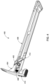
- the hammer-head 104 is pinned to the hammer-handle 102 by a pin 106 and can rotationally move with respect to handle 102 in a restricted manner.
- a spring 118 forces the hammer-head 104 to rotate counter-clockwise and stop rotating once it hits the hammer-handle 102 at point 108.
- the hammer-head 104 will rotate clockwise, while depressing spring 118, but stops rotating once it hits the hammer-handle 102 at point 110.
- Figure 2 shows an isometric exploded view of an example shock-absorbing hammer, where the hammer-handle 206 is relatively flat at the top and does not fork out, instead, the extension 213 of the hammer-head 200 is forked out (U- shaped, clevis, also called “two-wall clevis") to receive, enclose, and house the hammer-handle 206.
- the hammer-handle 206 enters the hammer-head 200 in the direction 212 and is pivoted to the hammer-head 200 by the pin set 202 and 204.
- the shock-absorbing mechanism set 214 is mounted between the hammer-head 200 and the hammer-handle 206.
- the handle cover or handle grip 208 is an optional component, which can receive the hammer-handle 206 through opening 210 and be removable or permanently attached to it.
- Figure 3 shows some details of the example shock-absorbing hammer-head of Figure 2 .
- the hammer-head 200 of Figure 2 is shown from another angle which more clearly illustrates the clevis 302 and the pin-holes 304.
- the clevis 302 will add more weight to the hammer-head 200 in comparison with the flat hammer-head extension of Patent ⁇ 953.
- the details of the design and structure of the clevis 302 can be manipulated as desired to be made bulkier and add to the mass of the hammer-head.
- the mass of the hammer-head in Patent ⁇ 953 cannot be changed as much as the hammer-head disclosed in this specification.
- the hammer-head of the present disclosure can be made heavier than the hammer-head in Patent ⁇ 953.
- FIG 4 shows isometric view of an example disclosed shock-absorbing hammer 400.
- This hammer is the assembled combination of the parts shown in Figure 2 .
- the hammer-head 404 has housed and is pivoted by pin 402 to the hammer-handle 412 which itself is housed within the optional handle-grip 406.
- the hammer-head 404 has a magnetized nail holder 410.
- the shock-absorbing mechanism 408 can be seen from outside of the hammer-head 404.
- the shock-absorbing mechanism 408 may be covered by an opaque or a clear component of the hammer-head.
- the shock-absorbing mechanism 408 may be adjustable through the mentioned opening without the need to remove the hammer-head 404 from the hammer-handle 412.
- the user can fix the hammer-head 604 to the hammer-handle 602 and make it a regular or traditional hammer, if desired.
- a similar adjustment may be provided to widen or restrict the gas or the air passage and, again, effectively change the characteristics of the shock-absorber or the mechanical filter.
- the opening or closing of the gas or the air passage will have extreme effects on the mechanical filter and in turn on the behavior of the hammer.
- the hammer-handle 206 can likewise be pivoted to the hammer-handle 206 by a pin set similar to the pin set 202 and 204. And again, the design details of the structure of the wall 701 can also be manipulated as desired to be made bulkier and increase the mass of the hammer-head 700.
Landscapes
- Engineering & Computer Science (AREA)
- Mechanical Engineering (AREA)
- Percussive Tools And Related Accessories (AREA)
- Vibration Dampers (AREA)
Applications Claiming Priority (1)
| Application Number | Priority Date | Filing Date | Title |
|---|---|---|---|
| US202318092904A | 2023-01-03 | 2023-01-03 |
Publications (1)
| Publication Number | Publication Date |
|---|---|
| EP4397443A1 true EP4397443A1 (de) | 2024-07-10 |
Family
ID=86692878
Family Applications (1)
| Application Number | Title | Priority Date | Filing Date |
|---|---|---|---|
| EP23177133.8A Pending EP4397443A1 (de) | 2023-01-03 | 2023-06-04 | Stossdämpfender hammer |
Country Status (5)
| Country | Link |
|---|---|
| EP (1) | EP4397443A1 (de) |
| KR (1) | KR20240109196A (de) |
| CN (1) | CN118288236A (de) |
| CA (1) | CA3216788A1 (de) |
| TW (1) | TWI898225B (de) |
Citations (6)
| Publication number | Priority date | Publication date | Assignee | Title |
|---|---|---|---|---|
| US6128977A (en) * | 1997-04-09 | 2000-10-10 | Emerson Electric Co. | Shock-absorbing claw hammer |
| US20030196521A1 (en) * | 2002-04-17 | 2003-10-23 | Tai-Her Yang | Hammer with resilient swivel pivoted joint |
| US8438953B2 (en) | 2011-01-24 | 2013-05-14 | Kuan-Wei Chen | Hammering tool with buffer design |
| DE202013101361U1 (de) * | 2013-03-28 | 2013-07-05 | Hsiu-Hua Chang | Hammer mit Dämpferbaugruppe |
| US20160319898A1 (en) * | 2010-12-23 | 2016-11-03 | Gaudet Machine Works Inc. | Force limiting device |
| CN207953756U (zh) * | 2018-02-01 | 2018-10-12 | 宜昌天宏建筑工程有限公司 | 一种应用于建筑领域的瓷砖铺设用的橡胶锤 |
Family Cites Families (1)
| Publication number | Priority date | Publication date | Assignee | Title |
|---|---|---|---|---|
| CN113618680B (zh) * | 2021-10-12 | 2021-12-07 | 如东恒发五金制品有限公司 | 一种减震新型高效五金工具锤 |
-
2023
- 2023-06-04 EP EP23177133.8A patent/EP4397443A1/de active Pending
- 2023-06-08 TW TW112121417A patent/TWI898225B/zh active
- 2023-10-17 CA CA3216788A patent/CA3216788A1/en active Pending
- 2023-12-28 KR KR1020230194521A patent/KR20240109196A/ko active Pending
- 2023-12-29 CN CN202311848730.2A patent/CN118288236A/zh active Pending
Patent Citations (6)
| Publication number | Priority date | Publication date | Assignee | Title |
|---|---|---|---|---|
| US6128977A (en) * | 1997-04-09 | 2000-10-10 | Emerson Electric Co. | Shock-absorbing claw hammer |
| US20030196521A1 (en) * | 2002-04-17 | 2003-10-23 | Tai-Her Yang | Hammer with resilient swivel pivoted joint |
| US20160319898A1 (en) * | 2010-12-23 | 2016-11-03 | Gaudet Machine Works Inc. | Force limiting device |
| US8438953B2 (en) | 2011-01-24 | 2013-05-14 | Kuan-Wei Chen | Hammering tool with buffer design |
| DE202013101361U1 (de) * | 2013-03-28 | 2013-07-05 | Hsiu-Hua Chang | Hammer mit Dämpferbaugruppe |
| CN207953756U (zh) * | 2018-02-01 | 2018-10-12 | 宜昌天宏建筑工程有限公司 | 一种应用于建筑领域的瓷砖铺设用的橡胶锤 |
Also Published As
| Publication number | Publication date |
|---|---|
| CA3216788A1 (en) | 2024-07-03 |
| TWI898225B (zh) | 2025-09-21 |
| CN118288236A (zh) | 2024-07-05 |
| KR20240109196A (ko) | 2024-07-10 |
| TW202428402A (zh) | 2024-07-16 |
Similar Documents
| Publication | Publication Date | Title |
|---|---|---|
| US7980323B2 (en) | Shock dampening post driver | |
| US11559879B2 (en) | Power tool | |
| CN101130241B (zh) | 冲击工具 | |
| JP4016772B2 (ja) | ハンマドリル | |
| AU2014271218B2 (en) | Rear handle | |
| US10040184B2 (en) | Rear handle | |
| EP0876882A2 (de) | Rückschlagfreier Klauhammer | |
| JP5126574B2 (ja) | 往復動工具 | |
| JP2017001148A (ja) | 打撃工具 | |
| CA3216788A1 (en) | SHOCK ABSORBING HAMMER | |
| CN102101285B (zh) | 手持式工具机 | |
| CN105715723A (zh) | 阻尼装置 | |
| CN101966597B (zh) | 一种防振切削工具 | |
| CN217168401U (zh) | 一种锤头可更换式特种工具锤 | |
| CN209604464U (zh) | 可满足舰船环境的减振装置 | |
| JPH0141575Y2 (de) | ||
| JP2005199408A (ja) | インパクトハンマー | |
| KR101224902B1 (ko) | 충격식 해머 장치 | |
| TWI630075B (zh) | 鎚擊式釘槍 | |
| CN223399157U (zh) | 一种可调间隙碰撞减振器 | |
| TW202204106A (zh) | 無反彈錘頭 | |
| JP2016187854A (ja) | 動力工具 | |
| CN211852649U (zh) | 一种油田钻井用主动减震器 | |
| US20250187165A1 (en) | Vibration dampening hammer | |
| CN216385682U (zh) | 一种惯性导航装置 |
Legal Events
| Date | Code | Title | Description |
|---|---|---|---|
| PUAI | Public reference made under article 153(3) epc to a published international application that has entered the european phase |
Free format text: ORIGINAL CODE: 0009012 |
|
| STAA | Information on the status of an ep patent application or granted ep patent |
Free format text: STATUS: THE APPLICATION HAS BEEN PUBLISHED |
|
| AK | Designated contracting states |
Kind code of ref document: A1 Designated state(s): AL AT BE BG CH CY CZ DE DK EE ES FI FR GB GR HR HU IE IS IT LI LT LU LV MC ME MK MT NL NO PL PT RO RS SE SI SK SM TR |
|
| STAA | Information on the status of an ep patent application or granted ep patent |
Free format text: STATUS: REQUEST FOR EXAMINATION WAS MADE |
|
| 17P | Request for examination filed |
Effective date: 20250109 |