EP0876882A2 - Rückschlagfreier Klauhammer - Google Patents
Rückschlagfreier Klauhammer Download PDFInfo
- Publication number
- EP0876882A2 EP0876882A2 EP98630011A EP98630011A EP0876882A2 EP 0876882 A2 EP0876882 A2 EP 0876882A2 EP 98630011 A EP98630011 A EP 98630011A EP 98630011 A EP98630011 A EP 98630011A EP 0876882 A2 EP0876882 A2 EP 0876882A2
- Authority
- EP
- European Patent Office
- Prior art keywords
- head
- handle
- striking
- hammer
- shock
- Prior art date
- Legal status (The legal status is an assumption and is not a legal conclusion. Google has not performed a legal analysis and makes no representation as to the accuracy of the status listed.)
- Withdrawn
Links
Images


Classifications
-
- B—PERFORMING OPERATIONS; TRANSPORTING
- B25—HAND TOOLS; PORTABLE POWER-DRIVEN TOOLS; MANIPULATORS
- B25D—PERCUSSIVE TOOLS
- B25D1/00—Hand hammers; Hammer heads of special shape or materials
- B25D1/12—Hand hammers; Hammer heads of special shape or materials having shock-absorbing means
Definitions
- This invention relates to hammers for driving nails and striking various objects and, in particular. shock-absorbing or dead blow hammers that reduce the recoil and vibration caused by the hammer strike. More particularly, the present invention relates to a non-rebounding. shock-absorbing hammer including a claw feature.
- a percussive tool such as a hammer
- strike part of the energy produced by the strike is used to perform desired work (e.g., drive a nail)
- desired work e.g., drive a nail
- part is converted into heat
- part is dissipated through the hammer.
- the energy that is dissipated through the hammer often produces undesirable results such as recoil of the hammer from the struck surface or excessive vibration of the hammer.
- the undesirable results produced by hammer strikes have been a persistent problem for the makers of hammers and other percussive tools.
- Kahlen Kahlen
- known methods for reducing hammer recoil included placing either a slug, a charge of round shot, or a charge of powdered material in a chamber immediately behind a striking face of the hammer, such that the object(s) placed behind the striking head will absorb some of the forces produced by the hammer strike.
- the particular approach disclosed in Kahlen involved the placement of a charge of irregularly-shaped, hard heavy particles in a chamber immediately behind the striking head of a hammer.
- a shock-absorbing hammer in accordance with one aspect of the invention includes a handle, a tension rebar positioned within the handle, a compression rebar positioned within the handle, a striking head coupled to the compression rebar and a claw head coupled to the tension rebar.
- the striking head and the claw head are adapted to move relative to one another.
- a shock-absorbing hammer in another aspect of the invention, includes a handle arid a head coupled to the handle.
- the head has a top surface and a lower surface, with the lower surface of the head coupled to the handle.
- the head defines a striking head and a claw, and at least a portion of the head defines a recess extending down from the top of the head.
- the head further defines a slit extending from the top surface of the head towards the lower surface of the head, wherein the slit extends through at least part of the portion of the head that defines the recess.
- a hammer in yet another aspect of the invention, includes a handle defining a first end which is opposite a second end.
- a striking assembly is coupled to the first end of the handle.
- the striking assembly includes a main striking head and a secondary striking head, and a claw feature is coupled to the second end of the handle.
- a shock-absorbing hammer having a claw feature has a striking head having a first end for striking objects and a second end.
- An upper handle portion includes a first and a second end with the claw feature being integrally attached at the upper handle first end forming a lagging mass.
- the upper handle second end defines a pocket adapted to receive the striking head second end in a manner such that the striking head and the claw feature move with respect to each other when the striking head strikes an object.
- a lower handle portion is hingedly attached to the upper handle portion such that the upper and the lower handle portions move pivotally with respect to each other when the striking head strikes an object, but remain fixed together when the claw feature is used.
- a shock-absorbing hammer including a handle, a rigid head cover affixed to the handle and defining a cavity therein.
- First and second striking heads are situated within the head cover, with each striking head including a striking portion and defining a circumferential collar.
- the first striking head defines a cavity adapted to slidably receive a lug extending from the second striking head.
- the head cover has first and second ends, each end defining an opening through which the striking portions of the first and second striking heads, respectively, extend.
- the head cover first and second ends each define a hard stop, against which the circumferential collars of the first and second ends, respectively, seat for preventing the striking heads from falling out of the head cover.
- a biasing member is situated between the circumferential collars for forcing the first and striking heads apart such that a gap is formed between the striking heads.
- a still further aspect of the invention includes a hammer for driving nails which has a handle and a striking head coupled to the handle.
- the striking head is adapted to strike and therefore drive a nail, wherein the construction of the striking head is such that vibrations are produced in the striking head when a nail is struck by the striking head.
- means coupled to the handle and to the striking head absorbs at least a portion of the vibrations produced when a nail is struck by the striking head.
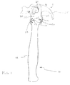
- Figure 1 illustrates a hammer constructed according to certain teachings of the present invention including upper and lower handle portions that are hingedly attached to one another and a claw portion integral with the upper handle portion.
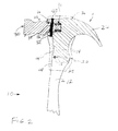
- Figure 2 illustrates an alternate embodiment of the hammer iliustrated in Figure 1.
- Figure 3 illustrates an alternate embodiment of the hammers illustrated in Figures 1 and 2.
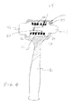
- Figure 4 illustrates a hammer constructed according to certain aspects of the present invention including first and second striking heads encapsulated in a load bearing cover.
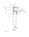
- Figure 5 illustrates yet another hammer constructed according to certain teachings of the present invention including a striking head and a claw and tension and compression rebars attached to the head and claw.
- Figures 6A, 6B and 6C illustrate still another hammer constructed according to certain aspects of the present invention that includes a head portion defining a recess and a slit that extends through the head portion.
- Figure 7 illustrates yet another hammer constructed according to certain teachings of the present invention in which a claw feature is connected to a handle opposite a head portion.
- the hammer 10 comprises a head portion 11, a lower handle portion 12 and an upper handle portion 14.
- the lower handle portion 12 may be fabricated out of wood or metal similarly to a standard carpenter's hammer, or vibration absorbing materials such as fiberglass or a rubber coated composite may be used.
- the upper handle portion 14 is hingedly attached to the lower portion 12, allowing the head portion to pivot relative to the handle 12.
- the hinge connection 20 may comprise a single lug extending from the lower portion 12 towards the upper handle portion 14.
- the upper handle portion 14 has two lugs extending therefrom in a spaced relationship whereby the lug of the lower handle portion 12 is received in between the two lugs of the upper handle portion 14.
- An aperture 16 extends through the lugs of the upper and lower handle portions and a pin 18 extends through the apertures whereby the upper handle portion 14 pivots about the pin 18 to hingedly attach the two handle portions.
- the junction of the lower handle portion 12 and the upper handle portion 14 opposite hinge 20 are held together by a spring clip 22 which may be fashioned out of typical spring steel.
- the head portion 11 includes the upper handle portion 14 with a claw portion 24 integral therewith.
- the claw 24 defines a generally elongated v-shaped opening (not shown) for pulling nails and the like.
- the upper handle portion 14 defines a pocket 26 fashioned to receive a striking head 28.
- the striking head 28 has a first end 30 for striking nails and other surfaces and a second end 32 that is received into the pocket 26 in a spaced relationship such that a gap 34 is formed between the second end 32 and the pocket 26.
- the striking head 28 "floats" in the pocket 26 of the upper handle 14.
- the gap 34 between the second end 32 of the floating striking head and the upper handle portion 14 is approximately 0.75 millimeters.
- end 32 of the striking head is slid inside pocket 26 in a piston fashion. This would prevent rotation of the head about an axis perpendicular to the paper in Figure 1.
- An elastomeric material preferably polyurethane 36, encapsulates the upper handle portion 14, the second end 32 of the floating striking head 28, and the portion of the lower handle 12 adjacent the hinge 20.
- the striking head 28 also includes a circumferential groove which allows the polyurethane encapsulation 36 to capture the striking head 28 and hold it in place within the encapsulation 36.
- the polyurethane encapsulation 36 works in conjunction with spring clip 22, forming a "composite spring,” to keep the hinged upper and lower handle portions closed, except when the hammer is used to strike an object, where the handles pivot apart slightly.
- the use of the embodiment of the dead blow hammer having a claw feature shown in Figure 1 is illustrated as follows.
- the floating striking head 28 hits the nail.
- the impact of the striking head 28 hitting the nail causes the polyurethane encapsulation 36 to deform, and the floating striking head 28 moves through the gap 34 between the striking head 28 and the upper handle portion 14, cushioning the blow and countering recoil.
- the upper handle 14 together with the claw portion 24 form a lagging mass. which contacts the second end 32 of the striking head 28 due to the momentum of the hammer 10 striking the nail, which also counters the tendencies of the hammer to recoil or rebound.
- the upper handle portion 14 pivots apart slightly from the lower handle portion 12, which provides vibration isolation of the handle.
- the claw portion 24 is slipped under the object to be pried.
- the lower handle portion 12 is moved in a direction opposite the claw portion 24.
- the location of the hinge 20 does not allow the upper and lower handles to pivot when the handle is moved in this direction, thereby creating a rigid lever for prying. This effect is accomplished because of the hinge location and because the faces 13 and 25 are in contact during nail pulling.
- FIG. 2 An alternate embodiment of a dead blow hammer in accordance with the present invention is pictured in Figure 2.
- the embodiment of Figure 2 has an upper handle portion 14 integral when the claw portion 24.
- a hinge 20 connects the upper handle portion 14 with the lower handle portion 12.
- the striking head 28 has a first end 30 for striking objects and a second end 32 which slidably fits into a pocket 26 formed in the upper handle portion 14.
- the second end 32 defines a bore 38 therethrough which is perpendicular to the axis of the head 28.
- a pin 40 couples the upper handle portion 14 to the striking head 28 by extending through the bore 38.
- the bore 38 through the striking head 28 has a diameter slightly larger than the pin 40 allowing the striking head 28 to axially move, or float.
- a biasing member such as a compression spring 42 is located within the pocket 26 of the upper head portion 14, biasing the striking head 28 away from the inner surface of the pocket 26, thereby maintaining a gap of approximately 0.75 millimeters between the striking head 28 and the upper handle portion 14.
- An elastomeric material such as polyurethane encapsulates the upper handle portion 14 and the lower handle 12 just below the hinge 20.
- the elastomeric material 36 acts as a spring and functions to hold the hinged upper handle portion 14 and lower handle portion 12 together, but allowing them to pivot slightly apart when the hammer strikes a nail or other object.
- Both the upper and lower handle portions have a series of teeth 44 for grabbing the elastomeric material 36 to better hold both handle portions in place.
- shock absorbing hammer may include the floating head 28 and lagging mass!claw 24 as in the embodiments of Figures 1 and 2, wherein the head 11 does not pivot with respect to the handle 12.
- FIG. 3 An alternate embodiment of the shock absorbing hammer illustrated in Figure 1 and Figure 2 is shown in Figure 3.
- the hammer of Figure 3 incorporates only the pivot feature of the embodiments of Figures 1 and 2 to absorb a portion of the shock of a nail strike.
- the shock-absorbing hammer 10 of Figure 3 includes a head 11 having an integral striking portion 28 and claw 24.
- the striking head 28 and integral claw 24 may be of a forged construction.
- the head 11 defines an opening 91 which may be generally rectangular shaped extending therethrough.
- a handle 12 includes an upper portion 14 which defines a top surface 92 and extends into the opening 91.
- the opening 91 has an axis that extends generally transverse to the axis defined by the head portion 11, such that the handle extends generally, perpendicular to the axis of the head portion 11.
- the handle 12 may be fashioned out of fiberglass, graphite, wood, metal, or other suitable material.
- a pin 18 extends through openings 94 in the head 11 and handle upper portion 14 to hingedly attach the upper portion 14 to the head 11.
- the pin 18 is located below the horizontal centerline 96 of the striking portion 28. In a preferred embodiment, the pin 18 is about 0.8 centimeters in diameter and the openings are positioned about 1 to 2.5 centimeters below the centerline 96.
- the handle upper portion 14 defines first and second notches 98, 100 on opposite sides of the upper portion 14.
- the first notch 98 extends from the upper surface 92 downward (as shown in Figure 3), terminating approximately even with the opening 94.
- the second notch 100 originates approximately even with the opening 94 and extends downward past the point where the head 11 meets the handle 12, denoted by reference numeral 102.
- the upper surface 92 and the first and second notches 98, 100 are filled with an elastomer 104.
- the arrangement of the notches 98, 100 is such that the elastomer 104 allows only clockwise rotation of the head 11 relative to the handle 12 (as illustrated in Figure 3). This allows the head 11 to pivot slightly with respect to the handle 12 to dampen the vibration of striking.
- the hammer 10 as illustrated in Figure 3 allows only a vary slight rotation -- less than a degree in one embodiment of the invention. This is enough to dampen the vibration while at the same time, not significantly affecting the angle of incidence of a nail strike.
- the rotation allowed is less than the range of angles that a typical hammer user would experience when striking several times -- the user does not hit the nail exactly flush with every hit.
- the notch 98, 100 and elastomer 104 arrangement do not allow rotational flexing during nail pulling because their design allows direct contact between the head 11 and handle 14 at contact points 110, 112. This allows for rigid, durable stiffness, which is necessary for the high loads experienced during nail pulling.
- FIG. 4 illustrates yet another embodiment of the present invention.
- This embodiment includes a handle portion 12 fashioned out of a rigid, non-elastomeric material such as metal or nylon, for example. Additional materials such as reinforced polypropylene may also be used.
- the handle 12 may include a rigid inner skeleton.
- This embodiment further includes first and second striking heads 46 and 48 which are aligned with each other.
- the striking heads 46 and 48 are encapsulated in a load bearing, rigid (non-elastomeric) head cover 50 which is attached to the handle 12.
- the head cover 50 may be integral with the handle 12.
- the head cover 50 has first and second openings 52 and 54 through which the first and second striking heads 46 and 48 extend.
- Each striking head 46 and 48 further includes a circumferential collar 56 and 58 which seats against hard stops formed by the inside surface of the head cover 50, preventing the striking heads 46 and 48 from falling out the head cover 50.
- the first striking head 46 includes a generally square-shaped cavity 60 which slidably receives a lug 62 extending from the second striking head 48. This allows the two striking heads 46 and 48 to move laterally (or axially) with respect to each other, but the shape of the cavity 60 and lug 62 prevent the two striking heads 46 and 48 from twisting relative to each other inside the head cover 50.
- a biasing member, such as a spring 64 is positioned between the two striking heads 46 and 48 forces the heads apart, creating a small air gap 66 between the two heads 46 and 48. For example, when one of the striking heads strikes an object, the remaining striking head acts as a lagging mass. The momentum of the strike causes the lagging mass to move in the direction of the strike against the spring 64 and impact the striking head.
- FIG. 5 an alternate embodiment of the present invention is shown having a handle 12, a striking head 28 and a claw 24.
- the striking head 28 has a generally square shaped cavity 60 adapted to slidably receive a lug 62 extending from claw 24.
- the shape of the cavity 60 and associated lug 62 prevent the striking head 28 from rotating relative to the claw 24.
- the claw 24 functions as a lagging mass and moves towards the striking head 28 upon the strike.
- the handle 12 includes a cradle or skeleton 68, which may be preform nylon.
- a compression rebar 70 and a tension rebar 72 are also positioned within the handle. The compression rebar 70 is attached to the striking head 28 and the tension rebar 72 is attached to the claw 24.
- An elastomeric material 36 such as polyurethane encapsulates the handle 12 and a portion of the striking head 28 and claw 24.
- the rebars 70 and 72 function to add bending stiffness between the handle and the head, but not shear stiffness. In other words, when the hammer is used to strike an object such as a nail the rebars allow the striking head 28 and the claw 24 to slide laterally relative to each other; however, when the claw 24 is used to pry or to pull a nail, the rebars add bending stiffness to aide in the prying or pulling. Teeth 71 on the rebars are encapsulated and retained by the elastomeric encapsulation 36.
- Figures 6A, 6B and 6C another exemplary embodiment of the present invention is shown, providing a no-shock, fatigue reducing hammer.
- Figure 6A is a front elevation view and Figure 6B shows a top plan view of this particular embodiment.
- a perspective view is shown in Figure 6C.
- the hammer of Figures 6A, 6B and 6C includes lower handle 12 and upper handle 14 portions. Upper handle portion 14 and lower handle portion handle 12 may be integrally attached, as shown in Figures 6A, 6B and 6C.
- a striking head 28 and a claw 24 are integral with the upper handle portion 14.
- the claw also includes generally elongated v-shaped opening 80 for pulling items such as nails.
- This embodiment may comprise an integral steel striking head 28, claw 24 and handle 12/14, or the handle may be fashioned out of a lightweight, vibration absorbing composite material with the striking head 28 and the claw 24 made of metal.
- the upper head portion 14 may define a recess 82 therein, extending down from the top of the upper head 14.
- recess is included which is generally rectangular shaped, having dimensions of approximately 2.5 x 1.5 centimeters, which is best shown in the top plan view of Figure 6A and the perspective view of Figure 6B.
- the recess 82 is about 4 centimeters deep, shown in phantom lines in Figure 6A and 6C.
- a wall thickness of about 0.3 centimeters is maintained between the recess and the outer surface of the hammer 10.
- a hard stop feature 88 prevents the slit 84 from opening significantly beyond the desired gap. This prevents the head 14 from breaking at the stress relief hole 86.
- the hard stop 88 comprises two pins 90 attached to the upper head portion 14 on either side of slit 84, with a link 92 having two holes 94 fit over the pins 90.
- Each of the holes 94 in the link 92 has a diameter that is larger than its corresponding pin 90, and the link is biased such that the slit 84 is allowed to close upon a hammer strike, but prevented from opening significantly beyond the desired gap.
- An alternate embodiment of the hard stop 88 is envisioned in which a staple-like member is disposed in holes on either side of the slit 84, each hole having a diameter larger than that of the staple member, again restraining the slit 84 from opening significantly, but not from closing.
- an elastomeric cover 36 may cover the upper handle portion 14, leaving the striking head 28 and the claw 24 exposed.
- the upper handle 14 and lower handle 12 may both be encapsulated with the elastomeric cover 36.
- the elastomeric cover 36 functions to cover the slit 84, preventing debris from clogging the slit 84. In the embodiment illustrated in Figure 6A-6C, the elastomeric cover 36 does not fill the slit 84, so the slit 84 is still able to close. Preventing the elastomeric cover 36 from filling the slit 84 may be accomplished by covering the slit 84 with a mask such as tape prior to encapsulating the handle.
- the elastomeric covering 36 may be applied by dipping the portion of the hammer 10 to be covered into the elastomeric covering material while the elastomeric material is in a liquid state, then allowing the elastomeric covering material to set on the hammer. Further, the elastomeric cover 36 provides a "soft fulcrum" area which would not damage a work piece when the claw 24 is used for pulling nails. Moreover, if the cover 36 extends to cover the lower handle portion 12, it provides a hand cushion for the user, which further reduces shock.
- the striking head 28 hits the object.
- the claw 24 functions as a lagging mass, and the slit 84 allows the claw 24 to move in the direction of the striking head 28 until contact is made between the claw 24 and the striking head 28, thereby deadening the blow and reducing recoil and vibration.
- the recess 82 functions to reduce the net area of contact between the striking head 28 and the claw 24 during the hammer strike, further deadening the blow and reducing the tendency of the hammer to recoil.
- Figure 7 illustrates an embodiment of the present invention which adds a claw feature 74 to the handle 12 opposite the striking head portion 76.
- this embodiment includes two striking heads, including a main striking head 28 comprising a common 16 ounce head for driving nails and a secondary head 29 which could include another nail driving head identical to the main striking head, a rubber mallet, a smaller nail striking head, or a rounded face nail driver for drywall.
- the striking head 76 may comprise any of the various embodiments of striking heads disclosed thus far, or it may be of the form of the striking head assembly disclosed in U.S. Patent No. 5,408,902, the entire disclosure of which is hereby incorporated by reference.
- the claw feature 74 connected to the handle 12 opposite the head portion 76 is similar to the claw on a standard carpenter's hammer, though it may be fashioned out of a lightweight material such as fiber-epoxy composite. Further, this claw feature 74 and handle 12 combination form a comfortable ergonomic hand pocket 78 for the user. It also functions as a safety feature, preventing the hammer from slipping out of the hands of the user and providing protection of the users hands. When the claw feature 74 is used for prying or pulling, the head portion 76 functions as a convenient handle grip to aid the user.
- the claw feature 74 extends from the handle 12 in a direction different from that illustrated.
- the claw feature 74 may extend in a direction generally perpendicular to an imaginary line passing through the striking surfaces of the two striking heads.
- An embodiment is also envisioned wherein the claw feature 74 is rotatably attached to the handle portion, whereby the claw can be rotated into a position that is either comfortable or convenient for the hammer user.
Landscapes
- Engineering & Computer Science (AREA)
- Mechanical Engineering (AREA)
- Percussive Tools And Related Accessories (AREA)
- Portable Nailing Machines And Staplers (AREA)
Applications Claiming Priority (4)
| Application Number | Priority Date | Filing Date | Title |
|---|---|---|---|
| US4205797P | 1997-04-09 | 1997-04-09 | |
| US09/005,198 US6128977A (en) | 1997-04-09 | 1998-01-09 | Shock-absorbing claw hammer |
| US42057 | 1998-01-09 | ||
| US5198 | 1998-01-09 |
Publications (2)
| Publication Number | Publication Date |
|---|---|
| EP0876882A2 true EP0876882A2 (de) | 1998-11-11 |
| EP0876882A3 EP0876882A3 (de) | 2003-07-23 |
Family
ID=26674049
Family Applications (1)
| Application Number | Title | Priority Date | Filing Date |
|---|---|---|---|
| EP98630011A Withdrawn EP0876882A3 (de) | 1997-04-09 | 1998-04-03 | Rückschlagfreier Klauhammer |
Country Status (6)
| Country | Link |
|---|---|
| US (1) | US6128977A (de) |
| EP (1) | EP0876882A3 (de) |
| JP (1) | JPH10329054A (de) |
| CN (1) | CN1069860C (de) |
| DE (1) | DE876882T1 (de) |
| TW (1) | TW436394B (de) |
Cited By (3)
| Publication number | Priority date | Publication date | Assignee | Title |
|---|---|---|---|---|
| ES2249113A1 (es) * | 2001-11-21 | 2006-03-16 | Snap-On Technologies, Inc. | Martillo de forja encapsulado con esqueleto perfeccionado. |
| FR3087372A1 (fr) * | 2018-10-22 | 2020-04-24 | Psa Automobiles Sa | Outil a main d’aide a la levee d’une agrafe de verrouillage d’un raccord |
| KR20250009269A (ko) * | 2023-07-10 | 2025-01-17 | 주식회사 한국건설방재연구원 | 다용도 해머 및 이의 사용방법 |
Families Citing this family (55)
| Publication number | Priority date | Publication date | Assignee | Title |
|---|---|---|---|---|
| US6763747B1 (en) * | 1997-04-09 | 2004-07-20 | Emerson Electric Co. | Shock absorbing hammer and handle assembly |
| US6158307A (en) * | 1999-05-05 | 2000-12-12 | General Housewares Corporation | Shock absorption system for a striking tool |
| US6386071B1 (en) * | 1999-12-13 | 2002-05-14 | M.O.M. Products, Inc. | Recoil reducing apparatus for striking tools |
| US6311582B1 (en) * | 2000-10-26 | 2001-11-06 | Howard Chow | Deadblow claw hammer |
| US6640447B2 (en) | 2001-12-18 | 2003-11-04 | Kenneth K. Wickline | Dead-blow recoilless axe |
| US6739218B2 (en) * | 2002-04-17 | 2004-05-25 | Tai-Her Yang | Hammer with resilient swivel pivoted joint |
| CN1311952C (zh) * | 2002-05-28 | 2007-04-25 | 杨泰和 | 构成沿捶击方向摆动的可摆动枢轴关节的锤具 |
| US6945138B1 (en) * | 2002-07-24 | 2005-09-20 | Kreitzer David F | Recoiling striking device |
| USD551529S1 (en) | 2002-08-07 | 2007-09-25 | Estwing Manufacturing Company | Hammer |
| US6647829B1 (en) | 2002-08-07 | 2003-11-18 | Estwing Manufacturing Company | Striking tool with weight forward head |
| CN100453121C (zh) * | 2002-11-12 | 2009-01-21 | 吴奕光 | 一种医用敷料及其生产方法 |
| FI115021B (fi) * | 2002-12-20 | 2005-02-15 | Nokia Corp | Suora ylössuuntainen pääsy |
| US6983674B1 (en) * | 2004-01-07 | 2006-01-10 | Rufolo Jr Joseph | Device and method for delivering an impact |
| USD549066S1 (en) | 2004-05-03 | 2007-08-21 | Estwing Manufacturing Company | Hammer |
| USD521342S1 (en) | 2004-05-03 | 2006-05-23 | Estwing Manufacturing Company | Hammer |
| US20060021474A1 (en) * | 2004-07-28 | 2006-02-02 | Michael Burgess | Double headed striking tool |
| US7168338B2 (en) * | 2004-11-29 | 2007-01-30 | Snap-On Incorporated | Dead blow hammer with composite holder |
| USD518684S1 (en) * | 2005-03-11 | 2006-04-11 | Robert Gerald Kushner | Hammer flask |
| CA2506986A1 (en) * | 2005-05-10 | 2006-11-10 | Garant Gp | A shaft for tools, and tool and a method of fabrication thereof |
| CA2544455A1 (en) * | 2006-04-21 | 2007-10-21 | Garant Gp | Hand tool |
| US8499665B2 (en) * | 2006-08-30 | 2013-08-06 | Stanley Black & Decker, Inc. | Torsion control hammer grip |
| US7320266B1 (en) | 2006-11-02 | 2008-01-22 | Kristopher Joseph Mueller | Shock dampening counterbalanced handle |
| US7448299B1 (en) * | 2008-04-17 | 2008-11-11 | Yung-Shou Chen | Hand tool with vibration-damping sleeve |
| US20090271929A1 (en) * | 2008-05-05 | 2009-11-05 | Robert Adams | Multi-function tool for demolition |
| USD600523S1 (en) | 2008-05-06 | 2009-09-22 | Robert Adams | Hammer |
| US7802497B1 (en) | 2008-08-11 | 2010-09-28 | Honda Motor Co., Ltd. | Impact absorbing striking tool |
| FR2940162B1 (fr) * | 2008-12-22 | 2011-02-25 | Boehm & Cie Ets | Outil de frappe multi-usages a mecanisme absorbant l'energie transmise au moyen de prehension |
| US8047099B2 (en) | 2009-02-09 | 2011-11-01 | Stanley Black & Decker, Inc. | Large strike face hammer |
| US9168648B2 (en) * | 2012-12-14 | 2015-10-27 | Stanley Black & Decker, Inc. | Vibration dampened hammer |
| US20140260812A1 (en) * | 2013-03-14 | 2014-09-18 | Hsiu-Hua Chang | Hammer with Buffer Assembly |
| US9016172B2 (en) * | 2013-05-29 | 2015-04-28 | Ying-Chieh Liao | Hammer |
| TW201501883A (zh) * | 2013-07-05 | 2015-01-16 | Lucky Brand Ind Co Ltd | 可調整操作角度之拔釘鎚 |
| US20150143959A1 (en) * | 2013-11-26 | 2015-05-28 | Shou King Enterprise Co., Ltd. | Striking tool |
| CN103737556A (zh) * | 2013-12-24 | 2014-04-23 | 苏州欢颜电气有限公司 | 一种多功能校正锤 |
| GB2541304B (en) * | 2014-03-07 | 2020-12-02 | Estwing Mfg Company | Striking tool with attached striking surface |
| TW201542328A (zh) * | 2014-05-07 | 2015-11-16 | xiu-hua Zhang | 減震式拔釘鎚 |
| US9327394B2 (en) * | 2014-05-13 | 2016-05-03 | Hsiu-Hua Chang | Claw hammer |
| US11485002B2 (en) * | 2014-07-14 | 2022-11-01 | Fiskars Brands, Inc. | Vibration reduction mechanism for a striking tool |
| US20160039078A1 (en) * | 2014-08-05 | 2016-02-11 | Joshua D. West | Hammer |
| TW201613730A (en) * | 2014-10-03 | 2016-04-16 | xiu-hua Zhang | Shock absorbing structure for a striking tool |
| EP3045270A1 (de) * | 2015-01-15 | 2016-07-20 | Hsiu-Hua Chang | Klauenhammer |
| CN105174157B (zh) * | 2015-10-10 | 2017-06-20 | 上海外高桥造船有限公司 | 撬杠 |
| TWI611882B (zh) * | 2016-01-26 | 2018-01-21 | 施瑞源 | 限力減震裝置 |
| TWI651172B (zh) * | 2016-01-26 | 2019-02-21 | 施瑞源 | 限力減震裝置 |
| US20180207780A1 (en) * | 2017-01-25 | 2018-07-26 | Lu Kang Hand Tools Industrial Co., Ltd. | Detachable hand tool made of different materials |
| US11358263B2 (en) | 2018-02-21 | 2022-06-14 | Milwaukee Electric Tool Corporation | Hammer |
| WO2019167767A1 (ja) | 2018-02-27 | 2019-09-06 | 株式会社トクヤマ | ハンマー |
| CN108686310B (zh) * | 2018-04-28 | 2022-06-24 | 南京涵铭置智能科技有限公司 | 一种轨道交通用破窗锤 |
| US11833651B2 (en) | 2019-02-07 | 2023-12-05 | Milwaukee Electric Tool Corporation | Hammer with hardened textured striking face |
| CN110774235B (zh) * | 2019-11-11 | 2023-07-14 | 徐州欧百瑞智能设备有限公司 | 一种设备维修用手锤 |
| EP4087708A4 (de) | 2020-01-10 | 2024-01-24 | Milwaukee Electric Tool Corporation | Hammer |
| CN112372585B (zh) * | 2020-10-23 | 2022-04-01 | 苏州昆卓精密制造有限公司 | 一种能够抵消反震力的锤子及其使用方法 |
| US20230043777A1 (en) * | 2021-08-06 | 2023-02-09 | Shu-Yi Lo | Pin fixing type hand tool structure |
| TWI807998B (zh) * | 2022-09-19 | 2023-07-01 | 施瑞源 | 限力減震裝置 |
| EP4397443A1 (de) * | 2023-01-03 | 2024-07-10 | Michael H. Panosian | Stossdämpfender hammer |
Family Cites Families (32)
| Publication number | Priority date | Publication date | Assignee | Title |
|---|---|---|---|---|
| US1045145A (en) * | 1912-11-26 | hubbard | ||
| US776191A (en) * | 1903-11-02 | 1904-11-29 | Thomas Jefferson Lynch | Implement for opening boxes or for other uses. |
| US1089234A (en) * | 1913-08-05 | 1914-03-03 | John Alexander Leslie | Hammer. |
| US1501095A (en) * | 1923-05-23 | 1924-07-15 | George F Brock | Hammer |
| US2604914A (en) * | 1944-05-13 | 1952-07-29 | Kahlen Johannes William | Hammer head having reboundpreventing means |
| US2737216A (en) * | 1953-12-23 | 1956-03-06 | Metocraft Alloy Corp | Recoil-less hammer head construction |
| US2940492A (en) * | 1955-07-22 | 1960-06-14 | Fayette R Plumb Inc | Fiber-glass reinforced percussive tool handle |
| FR1137125A (fr) * | 1955-11-29 | 1957-05-23 | Applic Mecaniques Electr Et Ae | Perfectionnements aux marteaux à têtes rapportées |
| US3000414A (en) * | 1956-03-16 | 1961-09-19 | Cordis Nat | Hammer |
| US2928444A (en) * | 1958-07-08 | 1960-03-15 | Olin Mathieson | Shockless hammer |
| US3030989A (en) * | 1961-01-25 | 1962-04-24 | Olin Mathieson | Hammer |
| US3148716A (en) * | 1962-04-02 | 1964-09-15 | Vanghan & Bushnell Mfg Co | Impact tool with chip-resistant striking face |
| DE1273449B (de) * | 1966-03-11 | 1968-07-18 | Carl Kuhbier | Rueckschlagfreier Hammer |
| US3704734A (en) * | 1970-04-28 | 1972-12-05 | Eduardo Rodriguez Soto | Tool having a head and a handle |
| US4039012A (en) * | 1976-01-12 | 1977-08-02 | C. E. S., Inc. | Non-rebound hammer |
| US4216808A (en) * | 1978-11-20 | 1980-08-12 | Eric Royce | Claw hammer |
| AR218840A1 (es) * | 1980-04-16 | 1980-06-30 | Rodriguez S | Mejoras en martillos con maza elastica |
| US4331193A (en) * | 1980-06-09 | 1982-05-25 | White Development Corporation | Flexible handle for percussive tool employing improved shaft member |
| US4498464A (en) * | 1982-06-21 | 1985-02-12 | Morgan Jr Darrell W | Chiropractic instrument |
| USD285284S (en) | 1982-07-26 | 1986-08-26 | Sunnex Equipment Ab | Hammer |
| US4697481A (en) * | 1985-02-21 | 1987-10-06 | Maeda Shell Service Co., Ltd. | Integrally molded hammer with separated head and handle cores |
| JPS62156482U (de) * | 1986-03-25 | 1987-10-05 | ||
| GB8619165D0 (en) * | 1986-08-06 | 1986-09-17 | Thor Hammer Co Ltd | Split head hammers |
| US4831901A (en) * | 1987-04-29 | 1989-05-23 | Kinne Arnold L | Carpenters hammer double jolt |
| US5118117A (en) * | 1991-01-08 | 1992-06-02 | Progenics Corporation | Recreational dart |
| DE9109131U1 (de) * | 1991-07-24 | 1991-09-19 | Erwin Halder KG, 7958 Laupheim | Schonhammer |
| US5249776A (en) * | 1992-09-14 | 1993-10-05 | Johnson Ray W | Adjustable leverage claw hammer |
| US5216939A (en) * | 1992-10-02 | 1993-06-08 | Swenson William B | Interchangeable tip and/or weight hammer |
| US5289742A (en) * | 1992-12-22 | 1994-03-01 | Vaughan & Bushnell Manufacturing Co. | Vibration damping device for hammers |
| DE4331660A1 (de) * | 1993-09-17 | 1995-03-23 | Halder Erwin Kg | Schonhammer |
| US5375487A (en) * | 1993-10-15 | 1994-12-27 | Zimmerman Packing & Mfg., Inc. | Maul head partially filled with shot |
| US5408902A (en) * | 1994-03-10 | 1995-04-25 | Burnett John A | Composite percussive tool |
-
1998
- 1998-01-09 US US09/005,198 patent/US6128977A/en not_active Expired - Fee Related
- 1998-04-03 DE DE0876882T patent/DE876882T1/de active Pending
- 1998-04-03 EP EP98630011A patent/EP0876882A3/de not_active Withdrawn
- 1998-04-08 CN CN98106219A patent/CN1069860C/zh not_active Expired - Fee Related
- 1998-04-09 TW TW087105334A patent/TW436394B/zh not_active IP Right Cessation
- 1998-04-09 JP JP10114127A patent/JPH10329054A/ja active Pending
Cited By (4)
| Publication number | Priority date | Publication date | Assignee | Title |
|---|---|---|---|---|
| ES2249113A1 (es) * | 2001-11-21 | 2006-03-16 | Snap-On Technologies, Inc. | Martillo de forja encapsulado con esqueleto perfeccionado. |
| ES2249113B1 (es) * | 2001-11-21 | 2007-05-01 | Snap-On Technologies, Inc. | Martillo de forja encapsulado con esqueleto perfeccionado. |
| FR3087372A1 (fr) * | 2018-10-22 | 2020-04-24 | Psa Automobiles Sa | Outil a main d’aide a la levee d’une agrafe de verrouillage d’un raccord |
| KR20250009269A (ko) * | 2023-07-10 | 2025-01-17 | 주식회사 한국건설방재연구원 | 다용도 해머 및 이의 사용방법 |
Also Published As
| Publication number | Publication date |
|---|---|
| DE876882T1 (de) | 1999-08-19 |
| CN1069860C (zh) | 2001-08-22 |
| CN1198978A (zh) | 1998-11-18 |
| TW436394B (en) | 2001-05-28 |
| EP0876882A3 (de) | 2003-07-23 |
| JPH10329054A (ja) | 1998-12-15 |
| US6128977A (en) | 2000-10-10 |
Similar Documents
| Publication | Publication Date | Title |
|---|---|---|
| US6128977A (en) | Shock-absorbing claw hammer | |
| US6016722A (en) | Shock-absorbing claw hammer | |
| US6763747B1 (en) | Shock absorbing hammer and handle assembly | |
| CA2601249C (en) | Torsion control hammer grip | |
| US6234048B1 (en) | Nonrecoil hammer | |
| US7980323B2 (en) | Shock dampening post driver | |
| AU2238095A (en) | A composite percussive tool | |
| US6311582B1 (en) | Deadblow claw hammer | |
| US20050252345A1 (en) | Non-recoil striking tool and process for making same | |
| CA2231058C (en) | Shock-absorbing claw hammer | |
| EP1421004B1 (de) | Schlagwerkzeug mit abplatzschutz | |
| US7320266B1 (en) | Shock dampening counterbalanced handle | |
| MXPA98002886A (en) | Horn absorbing shock hammer | |
| AU2024267063A1 (en) | Dead blow hammer head | |
| US20060157263A1 (en) | Percussion power tool apparatus | |
| TWI807998B (zh) | 限力減震裝置 | |
| WO2007082238A2 (en) | A functional polymer faced hammer for reduced vibration, noise, and improved ergonomics | |
| EP4338893B1 (de) | Handwerkzeug mit pufferungseffekt | |
| CA2299879A1 (en) | Shock absorbing hammer and handle assembly | |
| CN222405544U (zh) | 一种带有减震功能的锤子 | |
| MXPA98005838A (en) | Hammer of uña de golpe mue | |
| CN211220553U (zh) | 一种减震橡胶手锤 | |
| CN219666526U (zh) | 一种耐用性好的锤头 | |
| CN1205933A (zh) | 带卡爪的减震榔头 | |
| RU2140348C1 (ru) | Составной ударный инструмент |
Legal Events
| Date | Code | Title | Description |
|---|---|---|---|
| PUAI | Public reference made under article 153(3) epc to a published international application that has entered the european phase |
Free format text: ORIGINAL CODE: 0009012 |
|
| AK | Designated contracting states |
Kind code of ref document: A2 Designated state(s): AT BE CH CY DE DK ES FI FR GB GR IE IT LI LU MC NL PT SE |
|
| AX | Request for extension of the european patent |
Free format text: AL;LT;LV;MK;RO;SI |
|
| ITCL | It: translation for ep claims filed |
Representative=s name: RICCARDI SERGIO & CO. |
|
| EL | Fr: translation of claims filed | ||
| DET | De: translation of patent claims | ||
| RIC1 | Information provided on ipc code assigned before grant |
Ipc: 7B 25D 1/12 A |
|
| PUAL | Search report despatched |
Free format text: ORIGINAL CODE: 0009013 |
|
| AK | Designated contracting states |
Designated state(s): AT BE CH CY DE DK ES FI FR GB GR IE IT LI LU MC NL PT SE |
|
| AX | Request for extension of the european patent |
Extension state: AL LT LV MK RO SI |
|
| 17P | Request for examination filed |
Effective date: 20040123 |
|
| AKX | Designation fees paid |
Designated state(s): DE FR GB IT |
|
| STAA | Information on the status of an ep patent application or granted ep patent |
Free format text: STATUS: THE APPLICATION HAS BEEN WITHDRAWN |
|
| 18W | Application withdrawn |
Effective date: 20050504 |