EP4397497A1 - Tintenstrahlaufzeichnungsvorrichtung und verwaltungsverfahren für tintenstrahlaufzeichnungsvorrichtung - Google Patents
Tintenstrahlaufzeichnungsvorrichtung und verwaltungsverfahren für tintenstrahlaufzeichnungsvorrichtung Download PDFInfo
- Publication number
- EP4397497A1 EP4397497A1 EP22864030.6A EP22864030A EP4397497A1 EP 4397497 A1 EP4397497 A1 EP 4397497A1 EP 22864030 A EP22864030 A EP 22864030A EP 4397497 A1 EP4397497 A1 EP 4397497A1
- Authority
- EP
- European Patent Office
- Prior art keywords
- ink
- print head
- viscosity
- container
- solvent
- Prior art date
- Legal status (The legal status is an assumption and is not a legal conclusion. Google has not performed a legal analysis and makes no representation as to the accuracy of the status listed.)
- Pending
Links
Images





Classifications
-
- B—PERFORMING OPERATIONS; TRANSPORTING
- B41—PRINTING; LINING MACHINES; TYPEWRITERS; STAMPS
- B41J—TYPEWRITERS; SELECTIVE PRINTING MECHANISMS, i.e. MECHANISMS PRINTING OTHERWISE THAN FROM A FORME; CORRECTION OF TYPOGRAPHICAL ERRORS
- B41J2/00—Typewriters or selective printing mechanisms characterised by the printing or marking process for which they are designed
- B41J2/005—Typewriters or selective printing mechanisms characterised by the printing or marking process for which they are designed characterised by bringing liquid or particles selectively into contact with a printing material
- B41J2/01—Ink jet
- B41J2/135—Nozzles
- B41J2/165—Prevention or detection of nozzle clogging, e.g. cleaning, capping or moistening for nozzles
- B41J2/16517—Cleaning of print head nozzles
- B41J2/16552—Cleaning of print head nozzles using cleaning fluids
-
- B—PERFORMING OPERATIONS; TRANSPORTING
- B41—PRINTING; LINING MACHINES; TYPEWRITERS; STAMPS
- B41J—TYPEWRITERS; SELECTIVE PRINTING MECHANISMS, i.e. MECHANISMS PRINTING OTHERWISE THAN FROM A FORME; CORRECTION OF TYPOGRAPHICAL ERRORS
- B41J2/00—Typewriters or selective printing mechanisms characterised by the printing or marking process for which they are designed
- B41J2/005—Typewriters or selective printing mechanisms characterised by the printing or marking process for which they are designed characterised by bringing liquid or particles selectively into contact with a printing material
- B41J2/01—Ink jet
- B41J2/17—Ink jet characterised by ink handling
- B41J2/195—Ink jet characterised by ink handling for monitoring ink quality
-
- B—PERFORMING OPERATIONS; TRANSPORTING
- B41—PRINTING; LINING MACHINES; TYPEWRITERS; STAMPS
- B41J—TYPEWRITERS; SELECTIVE PRINTING MECHANISMS, i.e. MECHANISMS PRINTING OTHERWISE THAN FROM A FORME; CORRECTION OF TYPOGRAPHICAL ERRORS
- B41J2/00—Typewriters or selective printing mechanisms characterised by the printing or marking process for which they are designed
- B41J2/005—Typewriters or selective printing mechanisms characterised by the printing or marking process for which they are designed characterised by bringing liquid or particles selectively into contact with a printing material
- B41J2/01—Ink jet
-
- B—PERFORMING OPERATIONS; TRANSPORTING
- B41—PRINTING; LINING MACHINES; TYPEWRITERS; STAMPS
- B41J—TYPEWRITERS; SELECTIVE PRINTING MECHANISMS, i.e. MECHANISMS PRINTING OTHERWISE THAN FROM A FORME; CORRECTION OF TYPOGRAPHICAL ERRORS
- B41J2/00—Typewriters or selective printing mechanisms characterised by the printing or marking process for which they are designed
- B41J2/005—Typewriters or selective printing mechanisms characterised by the printing or marking process for which they are designed characterised by bringing liquid or particles selectively into contact with a printing material
- B41J2/01—Ink jet
- B41J2/07—Ink jet characterised by jet control
-
- B—PERFORMING OPERATIONS; TRANSPORTING
- B41—PRINTING; LINING MACHINES; TYPEWRITERS; STAMPS
- B41J—TYPEWRITERS; SELECTIVE PRINTING MECHANISMS, i.e. MECHANISMS PRINTING OTHERWISE THAN FROM A FORME; CORRECTION OF TYPOGRAPHICAL ERRORS
- B41J2/00—Typewriters or selective printing mechanisms characterised by the printing or marking process for which they are designed
- B41J2/005—Typewriters or selective printing mechanisms characterised by the printing or marking process for which they are designed characterised by bringing liquid or particles selectively into contact with a printing material
- B41J2/01—Ink jet
- B41J2/17—Ink jet characterised by ink handling
- B41J2/1707—Conditioning of the inside of ink supply circuits, e.g. flushing during start-up or shut-down
-
- B—PERFORMING OPERATIONS; TRANSPORTING
- B41—PRINTING; LINING MACHINES; TYPEWRITERS; STAMPS
- B41J—TYPEWRITERS; SELECTIVE PRINTING MECHANISMS, i.e. MECHANISMS PRINTING OTHERWISE THAN FROM A FORME; CORRECTION OF TYPOGRAPHICAL ERRORS
- B41J2/00—Typewriters or selective printing mechanisms characterised by the printing or marking process for which they are designed
- B41J2/005—Typewriters or selective printing mechanisms characterised by the printing or marking process for which they are designed characterised by bringing liquid or particles selectively into contact with a printing material
- B41J2/01—Ink jet
- B41J2/17—Ink jet characterised by ink handling
- B41J2/175—Ink supply systems ; Circuit parts therefor
- B41J2/17503—Ink cartridges
- B41J2/17506—Refilling of the cartridge
- B41J2/17509—Whilst mounted in the printer
-
- B—PERFORMING OPERATIONS; TRANSPORTING
- B41—PRINTING; LINING MACHINES; TYPEWRITERS; STAMPS
- B41J—TYPEWRITERS; SELECTIVE PRINTING MECHANISMS, i.e. MECHANISMS PRINTING OTHERWISE THAN FROM A FORME; CORRECTION OF TYPOGRAPHICAL ERRORS
- B41J2/00—Typewriters or selective printing mechanisms characterised by the printing or marking process for which they are designed
- B41J2/005—Typewriters or selective printing mechanisms characterised by the printing or marking process for which they are designed characterised by bringing liquid or particles selectively into contact with a printing material
- B41J2/01—Ink jet
- B41J2/17—Ink jet characterised by ink handling
- B41J2/175—Ink supply systems ; Circuit parts therefor
- B41J2/17566—Ink level or ink residue control
-
- B—PERFORMING OPERATIONS; TRANSPORTING
- B41—PRINTING; LINING MACHINES; TYPEWRITERS; STAMPS
- B41J—TYPEWRITERS; SELECTIVE PRINTING MECHANISMS, i.e. MECHANISMS PRINTING OTHERWISE THAN FROM A FORME; CORRECTION OF TYPOGRAPHICAL ERRORS
- B41J2/00—Typewriters or selective printing mechanisms characterised by the printing or marking process for which they are designed
- B41J2/005—Typewriters or selective printing mechanisms characterised by the printing or marking process for which they are designed characterised by bringing liquid or particles selectively into contact with a printing material
- B41J2/01—Ink jet
- B41J2/17—Ink jet characterised by ink handling
- B41J2/175—Ink supply systems ; Circuit parts therefor
- B41J2/17596—Ink pumps, ink valves
-
- B—PERFORMING OPERATIONS; TRANSPORTING
- B41—PRINTING; LINING MACHINES; TYPEWRITERS; STAMPS
- B41J—TYPEWRITERS; SELECTIVE PRINTING MECHANISMS, i.e. MECHANISMS PRINTING OTHERWISE THAN FROM A FORME; CORRECTION OF TYPOGRAPHICAL ERRORS
- B41J2/00—Typewriters or selective printing mechanisms characterised by the printing or marking process for which they are designed
- B41J2/005—Typewriters or selective printing mechanisms characterised by the printing or marking process for which they are designed characterised by bringing liquid or particles selectively into contact with a printing material
- B41J2/01—Ink jet
- B41J2/17—Ink jet characterised by ink handling
- B41J2/18—Ink recirculation systems
-
- B—PERFORMING OPERATIONS; TRANSPORTING
- B41—PRINTING; LINING MACHINES; TYPEWRITERS; STAMPS
- B41J—TYPEWRITERS; SELECTIVE PRINTING MECHANISMS, i.e. MECHANISMS PRINTING OTHERWISE THAN FROM A FORME; CORRECTION OF TYPOGRAPHICAL ERRORS
- B41J2/00—Typewriters or selective printing mechanisms characterised by the printing or marking process for which they are designed
- B41J2/005—Typewriters or selective printing mechanisms characterised by the printing or marking process for which they are designed characterised by bringing liquid or particles selectively into contact with a printing material
- B41J2/01—Ink jet
- B41J2/17—Ink jet characterised by ink handling
- B41J2/18—Ink recirculation systems
- B41J2/185—Ink-collectors; Ink-catchers
Definitions
- the present invention relates to an inkjet recording apparatus and a management method for the inkjet recording apparatus.
- a print head of such inkjet recording apparatus is provided with a charging electrode which gives an amount of charge as a function of printing information to ink particles spouted out from a nozzle and a deflecting electrode which deflects the charged ink particles and a gutter is disposed opposite to the nozzle to collect ink not used for printing.
- An ink supply path to supply ink in an ink container is connected to the nozzle and a collection path to collect ink collected by the gutter into the ink container makes a connection between the gutter and the ink container.
- a suction path makes a connection between an inflow port of the nozzle and the ink container to suck outside air into the nozzle and prevent nozzle clogging.
- a solvent supply path makes a connection between a solvent container and the nozzle for the purpose of cleaning the nozzle and each of the above-mentioned paths.
- an inkjet recording apparatus comprising an ink container in which ink for printing on printing target objects is contained, a nozzle which is connected to the ink container and from which pressurized and supplied ink is discharged, a charging electrode which charges ink particles discharged from the nozzle, a deflecting electrode which deflects ink particles charged by the charging electrode, a gutter which collects ink not used for printing, a solvent container in which a solvent is contained, and a liquid nozzle which is connected to the solvent container and from which pressurized and supplied solvent is discharged, characterized in that the liquid nozzle has a liquid path part extending from the nozzle toward the gutter and a liquid outlet opening part formed at an angle to let the pressurized and supplied solvent flowing through the liquid path part spout out and hit against the nozzle" is disclosed in Patent Literature (PTL) 1.
- an inkjet recording apparatus comprising a nozzle which spouts out ink particles that are generated, a charging electrode which charges the spouted out ink particles with a signal corresponding to characters or an image, a deflecting electrode to deflect the charged ink particles, a gutter which catches the ink particles not used for forming characters or an image, a main ink tank into which the ink particles caught by the gutter are returned for reuse of ink in forming characters or an image, an ink replenishment means which replenishes the main ink tank with replenishing ink as much as a quantity of ink consumed for forming characters or an image, an intensifier replenishment means which replenishes the main ink tank with an replenishing intensifier as much as a quantity of volatilized intensifier, and a liquid quantity detection means which detects a quantity of ink liquid accumulated in the main ink tank, characterized in that the liquid quantity detection means is capable of detecting a plurality of liquid levels including high, middle, and low levels and a liquid level
- viscosity of ink in a main ink container changes and may fall outside an appropriate range of viscosity and the viscosity may become high or low.
- the present invention solves problems associated with prior art mentioned above and provides an inkjet recording apparatus provided with configurations that enable it to prevent ink from sticking during inactivity and to adjust ink viscosity to fall within an appropriate range in an event when viscosity of ink in the main ink container has fallen outside the appropriate range of viscosity and a management method for such inkjet recording apparatus.
- an inkjet recording apparatus comprising a print head which is equipped with a nozzle to discharge ink and prints on printing target objects; a main body comprising an ink container in which ink to be supplied to the print head is contained, a solvent container in which a solvent is contained, a supply path to supply the ink from the ink container to the print head, a circulation path to return a part of the ink supplied to the print head to the ink container, and a collection path to suck the ink spouted out from the nozzle of the print head and collect the ink to the ink container; and a control unit which controls the print head and the main body; during inactivity of printing on the printing target objects by the print head, the control unit controls the print head and the main body to perform repetitively supplying the solvent contained in the solvent container to the print head and letting the solvent flow back to the ink container through the circulation path and the collection path at intervals of a certain period of time
- supplying a solvent to the print head and spouting out the solvent from the nozzle allow liquid to pass through a circulation path; this leads to capability to improve effectiveness of sticking prevention.
- the head receptacle unit 3 which will be described hereinafter is configured with the addition of the function of cleaning the print head.
- One inkjet recording apparatus 600A is depicted with the print head 2 being set up beside a production line.
- the other inkjet recording apparatus 600B is depicted with the print head 2 being removed from the production line and put (set) in place in the head receptacle unit 3.
- the head receptacle unit 3 is situated stationary near the belt conveyor 11; however, the head receptacle unit 3 can be re-installed freely in a place where it is easy to operate by the user.
- the inkjet recording apparatus 600B is depicted in a state when the head receptacle unit 3 is secured to the main body 1 by engaging its fitting part 93 with the fixing part 91 assembled to the main body 1.
- the head receptacle unit 3 can be seated in place, even if there is no space to install the head receptacle unit 3, inter alia, in proximity to the belt conveyor 11.
- the print head 2 is set in place in the head receptacle unit 3 of the inkjet recording apparatus 600B.
- the print head 2 is inserted into the head holding part 81A of the head receptacle unit 3 from its forward end and the print head 2 is set in place.
- the inkjet recording apparatus 600B according to the embodiment disclosed herein enables cleaning of the print head 2 with a solvent 69A that is supplied from the main body 1 side via the cable (for the head receptacle unit) 6.
- the inkjet recording apparatus 600A enables cleaning of the print head 2 also in a state when the print head 2 is set in place in the head receptacle unit 3 that is fixed by engaging its fitting part 93 with the fixing jig 92 assembled to the belt conveyor 11.
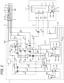
- Fig. 2 is a diagram depicting an overall path configuration in the inkjet recording apparatus 600 according to the embodiment disclosed herein.
- the main body 1 is equipped with a main ink container 31 which preserves ink 68A for printing.
- the main ink container 31 is equipped with a liquid level sensor 31A (a sensor 1) which detects a condition that the liquid (ink 68A) in the main ink container 31 exceeds a reference liquid level indicative of an appropriate amount for being preserved inside, a liquid level sensor 31B (a sensor 2) which detects whether or not the liquid reaches the reference liquid level indicative of the appropriate amount, and a liquid level sensor 31C (a sensor 3) which detects the termination of discarding a certain amount of the ink from the main ink container 31.
- a liquid level sensor 31A a sensor 1 which detects a condition that the liquid (ink 68A) in the main ink container 31 exceeds a reference liquid level indicative of an appropriate amount for being preserved inside
- a liquid level sensor 31B a sensor 2 which detects whether or not the liquid reaches the reference liquid level indicative of the appropriate amount
- a liquid level sensor 31C a sensor 3 which detects the termination of discarding a certain amount of the ink from the main ink container 31.
- the main ink container 31 is connected with a path (for supply) 801 in its portion filled with the ink 68A and a solenoid valve (for supply) 49 which opens and closes the path is installed in the middle of the path 801.
- the path 801 is then connected with a pump (for supply) 34 which is installed in a path 802 and used to suck and pump the ink 68A via a joint path 901.
- the path is in turn connected with a filter (for supply) 39 which removes foreign matters mixed in the ink 68A at the output side of the pump (for supply) 34.
- the filter (for supply) 39 is connected with a pressure regulating valve 46 which regulates the pressure of the ink 68A pumped out from the pump (for supply) 34 to be suitable for printing and the pressure regulating valve 46 is connected with a pressure sensor 38 which measures the pressure of the ink 68A being supplied to a nozzle 21.
- the path 802 in which the pressure regulating valve 46 is located is connected with a path 803 passing through the cable (for the print head) 5 via a branch path 921 and the path 803 is connected with a solenoid valve for switchover 26 which is provided inside the print head 2 and serves to control whether to supply the ink 68A to the nozzle 21.
- a heater 20 is installed which serves to raise the temperature of the ink 68A being supplied to the nozzle 21 to an optimal temperature.
- the heater 20 is internally equipped with a temperature sensor, which is not depicted, for control in raising the ink temperature.
- the solenoid valve (for switchover) 26 is connected with the nozzle 21 to discharge the ink 68A via a filter 27.
- the solenoid valve (for switchover) 26 is a three-way solenoid valve.
- the path 803 for ink supply and a path 825 for nozzle cleaning are connected to the solenoid valve (for switchover) 26 and this valve is able to switch over between the ink 68A and a solvent 69A being supplied to the nozzle 21.
- a charging electrode 23 to apply a predetermined charge amount to the ink particles 68B
- a deflecting electrode 24 to deflect the ink particles 68B for use for printing
- a gutter 25 to catch ink particles 68B flying straight without being charged and deflected, as they are not used for printing, are arranged in place.
- paths 811 and 812 for ink collection in the inkjet recording apparatus 600 are provided.
- the gutter 25 is connected with a path 811 and a charge sensor 48 is located in the path 811 to detect whether there are collected ink particles 68B to which a charge amount was applied by the charging electrode 23.
- the path 811 passes through the cable (for the print head) 5 and is connected with a filter (for collection) 40 which is located inside the main body 1 and removes foreign matters mixed in the ink and the filter (for collection) 40 is connected with a solenoid valve (for collection) 50 which opens and closes the path.
- the solenoid valve (for collection) 50 is connected with a pump (for collection) 35 which is located in a path 812 connected via a joint path 902 and suctions the ink particles 68B caught by the gutter 25.
- the pump (for collection) 35 is connected to the main ink container 31.
- an exhaust path (a path 814) in the inkjet recording apparatus 600 according to the embodiment disclosed herein.
- the exhaust path is configured such that one end of the path 814 is connected to the main ink container 31 in an upper space not contacting the ink 68A in the container and the other end of the path 814 is connected to an exhaust duct connection port 62 communicating with space outside the main body 1.
- ink circulation paths paths 821 to 822 in the inkjet recording apparatus 600 according to the embodiment disclosed herein.
- the nozzle 21 provided inside the print head 2 is connected with a path 821 passing into and through the cable (for the print head) 5 besides the path through which the ink 68A is supplied via the filter 27.
- a solenoid valve (for circulation) 59 which is provided inside the main body 1 and opens and closes the path (flow path) is located.
- the solenoid valve (for circulation) 59 is connected with a path 822 via a joint path 903 and a pump (for circulation) 36 which suctions the ink from the nozzle 21 is located in the path 822. Circulation is configured such that the pump (for circulation) 36 is in turn connected to the main ink container 31 through the path 822.
- paths 824 to 822 for viscosity measurement in the inkjet recording apparatus 600 according to the embodiment disclosed herein.
- the main ink container 31 is connected with a path (for viscosity measurement) 824 in its portion filled with the ink 68A.
- the solvent container 33 is connected with a path 831 in its portion filled with the solvent 69A and a pump (for solvent) 37 which is used to suck and pump the solvent is located in the path 831. Furthermore, the pump (for solvent) 37 is connected with a branch path 922 to change the destination to which the solvent 69A is supplied depending on the purpose.
- Path configuration for resupply of the solvent is such that the branch path 922 is connected with a solenoid valve (for resupply of solvent) 53 located in a path 833 to open and close the path and the solenoid valve (for resupply of solvent) 53 is connected to the main ink container 31 through the path 833.
- control of viscosity of the ink 68A in the main ink container 31 is performed under control of the control unit 7.
- a path 816 for exhaust makes a connection between the solvent container 33 and the exhaust duct connection port 62 to discharge evaporated solvent outside in a case when the solvent 69A evaporates inside the solvent container 33 and the internal pressure of the solvent container 33 rises.
- the auxiliary ink container 32 is connected with the path 806 in its portion filled with the ink 68C.
- the path 806 is connected with a solenoid value (for resupply of ink) 54 which opens and closes the path and the solenoid value (for resupply of ink) 54 is connected with the pump (for supply) 34 which is installed in the path 802 and used to suck and pump the ink 68C via the joint path 901.
- a path 815 for exhaust makes a connection between the auxiliary ink container 32 and the exhaust duct connection port 62 to discharge evaporated solvent outside in a case when solvent in the ink 68C evaporates inside the auxiliary ink container 32 and the internal pressure of the auxiliary ink container 32 rises.
- the path 802 is connected with a path 808 via the branch path 921.
- the path 808 is connected with a solenoid valve (for circulation in the main body) 58 and the solenoid valve (for circulation in the main body) 58 is connected with the pump (for collection) 35 installed in the path 812 via the joint path 902.
- the main body 1 is equipped with a pump (for drying) 60 which is used to suck and pump air and the pump (for drying) 60 has an air suction port formed therein communicating with the interior of the main body 1.
- the pump (for drying) 60 is connected to the head receptacle unit 3 through the path 841 passing into and through the cable (for the head receptacle unit) 6.
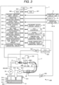
- 306 is a readonly memory (ROM) storing programs and data for control which are required for the MPU 301 to operate.
- 307 is a random access memory (RAM) storing data temporarily required during program execution by the MPU 301.
- 8 is the operating and display unit via which what is to be printed, setting values, etc. are input and which displays, inter alia, data and what is to be printed which have been input.
- a touch-input display panel with transparent touch switches superimposed on the surface of a liquid crystal display screen is used here.
- the control unit 7 also includes a printing-use charging signal generating circuit 342 and a phase search-use charging signal generating circuit 341 and includes a D/A converter 343 which converts a charging signal in a digital signal form which is output from these circuits to a voltage signal in an analog form and an amplifier circuit 344 which amplifies a voltage signal in an analog signal form which is output from the D/A converter 343 and generates a charging voltage to be applied to the charging electrode 23.
- a printing-use charging signal generating circuit 342 and the phase search-use charging signal generating circuit 341 there may be an implementation through a charge amount control by the control unit using only the printing-use charging signal generating circuit 342.
- the inkjet recording apparatus 600 is also equipped with a deflection voltage generating circuit 332 which generates a deflection voltage to be applied to the deflecting electrode 24.
- the inkjet recording apparatus 600 is also equipped with an amplifier circuit 353 which amplifies a phase detection signal in an analog signal form which is output from the charge sensor 48, a phase decision circuit 351 which takes input of an amplified phase detection signal and decides whether or not a charged quantity is acceptable, and an A/D converter 352 takes input of an amplified phase detection signal and performs A/D conversion.
- an amplifier circuit 353 which amplifies a phase detection signal in an analog signal form which is output from the charge sensor 48
- a phase decision circuit 351 which takes input of an amplified phase detection signal and decides whether or not a charged quantity is acceptable
- an A/D converter 352 takes input of an amplified phase detection signal and performs A/D conversion.
- the MPU 301 is also connected with and is to control a pump control circuit 321 to control the pumps 60 and 61, a collection container sensor detection circuit 322 to detect that the collection container 4 is attached to the head receptacle unit 3 and that liquid 70 in the collection container 4 is not more than a predetermined quantity using the magnetic sensor 76A and the magnet 75, a print head detection circuit 323 to detect that the print head 2 is put in place in the head receptacle unit 3, and a head receptacle unit detection circuit 324 to detect that the print head 2 is put in place in the head receptacle unit 3.
- a pump control circuit 321 to control the pumps 60 and 61
- a collection container sensor detection circuit 322 to detect that the collection container 4 is attached to the head receptacle unit 3 and that liquid 70 in the collection container 4 is not more than a predetermined quantity using the magnetic sensor 76A and the magnet 75
- a print head detection circuit 323 to detect that the print head 2 is put in place in the head recept
- control unit 7 can be made up of the MPU 301, the memories (306 and 307) to store programs for operation of the MPU 301 and data and information necessary for operation, and drive components to cause the print head 2, the head receptacle unit 3, and the hardware components within the main body 1 to operate, as instructed by the MPU 301. Detailed descriptions on the control unit 7 are omitted here.
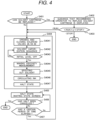
- FIG. 4 A processing flow of the operation for preventing ink sticking is depicted in Fig. 4 .
- the MPU 301 of the control unit 7 based on the stored control program, checks how much the solvent 69A for cleaning the print head 2 is in the solvent container 33 from the signal of the level sensor 33A and 33B and checks whether the solvent cartridge 69B containing solvent that is supplied as the solvent 69A to the solvent container 33 can be replaced (S401).
- the MPU 301 decides that the solvent cartridge 69B can be replaced (Yes at S401), as there is a small amount of the solvent 69A in the solvent container 33, and the processing goes to S402. Otherwise, if the level sensor 33A makes detection of the solvent 69A in the solvent container 33, the MPU 301 decides that the solvent cartridge 69B cannot be replaced (No at S401), as there is a sufficient amount of the solvent 69A in the solvent container 33, and the processing goes to a sticking prevention step (S404).
- the MPU 301 controls the solenoid valve driving circuit 315 to open and close the solenoid valve (for resupply of ink) 54, the solenoid valve (for switchover) 26, and the solenoid valve (for head cleaning) 56 repetitively (S4041) to prevent ink deposited to the solenoid valves 54, 26, and 56 from sticking with which the solenoid valves 54, 26, and 56 do not open and close smoothly.
- the MPU 301 controls the pump control circuit 314 to actuate the pump (for collection) 35 and, in the meantime, the solenoid valve (for collection) 50 is opened to suck air from the gutter 25 so that the air will be supplied through the paths (for collection) 811 and 812 into the main ink container 31, as is depicted in Fig. 5 .
- the air supplied into the main ink container 31 flows through the path (for exhaust) 814, comes to the exhaust duct connection port 62, and is discharged by an exhaust discharging means which is not depicted. In this way, by letting the air suctioned from the gutter 25 flow through the interior of the main ink container 31 and come to the exhaust duct connection port 62, the solvent in the main ink container 31 is vaporized (volatilized).
- Vaporizing the solvent in the main ink container 31 by letting the air suctioned from the gutter 25 flow through the interior of the main ink container 31 and come to the exhaust duct connection port 62 is continued until the liquid level sensor 31B no longer detects the ink 68A with descending of the liquid level of the ink 68A in the main ink container 31 and the ink 68A comes to an initial liquid level (at which detection of the liquid level of the ink 68A by the liquid level sensor 31B is turned from OFF to ON and vice versa) (S4043).
- the control unit By energizing the solenoid valve (for supply) 49 and the solenoid valve (for circulation in the main body) 58 to open one of the routes and actuating the pump (for supply) 34 and the pump (for collection) 35, the control unit lets the ink 68A contained in the main ink container 31 flow along the routes passing through the path (for supply) 801 and the path (for circulation in the main body) 808 and leading to the path (for collection) 812.
- the control unit checks whether a certain period of time has elapsed after the halt state is entered at S4047 (S407); if a certain period of time does not elapse (No at S407), the processing returns to S405.
- step S810 If the judgment at S8031 is that viscosity of the ink 68A is higher than the appropriate range ("high” at S8031), the processing goes to step S810. Otherwise, if the judgment is that viscosity of the ink 68A is lower than the appropriate range ("low” at S8031), the processing goes to step S830.
- the control unit opens the solenoid valve (for resupply of solvent) 53 to link up the path (for solvent supply) 831 and the path (for resupply of solvent) 833 leading to the main ink container 31 from the solvent container 33, as is indicated by a thick dotted line in Fig. 12 , and, in this condition, actuates the pump (for solvent) 37. Consequently, the solvent 69A contained in the solvent container 33 is resupplied into the main ink container 31 through the paths 831 and 833 (S814).
- the control unit closes the solenoid valve (for resupply of solvent) 53 to stop supply of the solvent 69A from the solvent container 33 to the main ink container 31.
- the solenoid valve for resupply of solvent
- a way of measuring viscosity of the ink 68A here is performed, while circulating the ink 68A by supplying the ink 68A from the main ink container 31 to the print head 2, catching the ink by the gutter 25, and collecting it to the main ink container 31 through the paths (for collection) 811 and 812.
- the control unit decides that ink viscosity has fallen within an appropriate range. As instructed by the CPU 301, by closing the solenoid valve (for supply) 49 and deactivating the pump (for supply) 34 in Fig. 13 , the control unit stops the supply of the ink 68A to the print head 2 and stops ink spouting from the nozzle 21 of the print head 2 (S818) and, besides, closes the solenoid valve (for viscosity measurement) 57 to stop the supply of ink to the viscosity measuring instrument 45.
- the control unit opens the solenoid valve (for collection) 50 and the solenoid valve (for circulation) 59 to make the path (for circulation via the head) 821 and the path (for collection) 811 passable from the print head 2 to the main ink container 31, so that the solvent 69A supplied to the print head 2 will be collected to the main ink container 31 through the path (for circulation via the head) 821 and the path (for collection) 811. Consequently, ink 68A remaining in the path (for circulation via the head) 821, the path (for collection) 811, the nozzle 21, and the gutter 25 is washed away and circulation path cleaning is performed (S819).
- control unit actuates the pump (for drying) 60 to blow air toward the print head 2 from a supply nozzle 73 having an air outlet and actuates the pump (for suction) 61 to remove air inside the head receptacle unit 3, so that the print head 2 getting wet with the solvent 69A will be let to dry; then, the step of longer head cleaning is terminated.
- the control unit makes the apparatus enter in a halt state (S821), terminates a series of the steps for normalizing ink viscosity, and displays an initial value of ink viscosity (measured at S803) and a value to which viscosity was adjusted (measured at S816) in an ink viscosity display field 80 provided on the operating and display unit 8, as is depicted in Fig. 17 .
- information that is presented in the ink viscosity display field 80 instead of values themselves of ink viscosity, information on ink viscosity may be displayed (e.g., "ink viscosity is high and has to be adjusted", “viscosity falls within an appropriate range", etc.).
- step S820 longer head cleaning may be skipped.
- step S830 and subsequent steps are executed and adjustment is made to make the low ink viscosity fall within the appropriate value range.
- step S830 the state in Fig. 9 is changed to the state in Fig. 10 to start ink spouting via the print head 2.
- the control unit closes the solenoid valve (for viscosity measurement) 57 to deactivate the pump (for circulation) 36, so that the ink 68A will not flow via the viscosity measuring instrument 45.
- the control unit also closes the solenoid valve 58, so that the ink 68A in the main ink container 31 will not circulate.
- the control unit opens the solenoid valve (for switchover) 26 and links up the paths (for supply) 801, 802, and 803, so that the ink 68A will be supplied from the main ink container 31 to the print head 2, thus starting ink spouting from the nozzle 21.
- the control unit opens the solenoid valve (for collection) 50 to open the ink collection path comprised of the path (for collection) 811 and the path (for collection) 812, so that the ink 68A supplied to the print head 2 and spouted out from the nozzle 21 will be caught by the gutter 25 and collected into the main ink container 31.
- the amount of ink 68A collected into the main ink container 31 through the ink collection path after being caught by the gutter 25 decreases as much as a quantity of volatilized solvent and the liquid level of the ink 68A contained in the main ink container 31 continues to fall.
- a detection signal of the ink 68A output by the liquid level sensor 31B (sensor 2) installed in the main ink container 31 is turned OFF (making no detection) (Yes at S832).
- This state sustains until a predetermined period of time has elapsed after the detection signal by the liquid level sensor 31B (sensor 2) is turned OFF (making no detection). Consequently, the liquid level of the ink 68A contained in the main ink container 31 becomes lower than the liquid level that is detected by the liquid level sensor 31B (sensor 2).
- the above-mentioned predetermined period of time after the detection signal of the ink 68A by the liquid level sensor 31B (sensor 2) is turned OFF (making no detection) (Yes at S832) is determined using a conditional expression preset in the MPU 301 depending on the viscosity of the ink measured at S803 and temperature of the ink measured with a temperature sensor which is not depicted. If the detected ink viscosity falls outside the appropriate range to a large extent, the predetermined period of time is set longer; if the detected ink viscosity falls outside the appropriate range to a comparatively small extent, the predetermined period of time is set shorter.
- a quantity of solvent to be vaporized from the ink 68A is thus adjusted depending on the ink viscosity; this eliminates the need to discard all the ink 68A in the main ink container 31 and replace it with new ink even when the ink viscosity is lower than an appropriate range, so that ink can be used effectively with a reduction of the quantity of discarded ink.
- the control unit outputs an abnormality message on the operating and display unit 8 (S8322) and closes the solenoid valve 49 to stop ink supply to the print head 2.
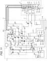
- the control unit closes the solenoid valve (for supply) 49 and opens the solenoid valve (for resupply of ink) 54, as is depicted in Fig. 16 . Consequently, supply of the ink 68A from the main ink container 31 to the print head 2 is stopped and the ink 68C contained in the auxiliary ink container 32 is supplied through a route comprised of the path (for resupply) 806 and the paths (for supply) 802 and 803 to the print head 2 and is spouted out from the nozzle 21.
- This ink 68C spouted out from the nozzle 21 is caught by the gutter 25 and is collected into the main ink container 31 through the ink collection path.
- the ink 68C contained in the auxiliary ink container 32 is thus resupplied to the main ink container 31 (S833).
- the control unit actuates the pump (for circulation) 36 and opens the solenoid valve (for viscosity measurement) 57 to link up the path (for viscosity measurement) 824 and the path (for circulation via the head) 822, as is depicted in Fig. 16 , so that the ink 68A contained in the main ink container 31 will flow via the viscosity measuring instrument 45, and viscosity of the ink 68A is measured (S835).
- the control unit outputs an abnormality message on the operating and display unit 8 (S8322) and closes the solenoid valve (for resupply of ink) 54 to stop the resupply of the ink 68C from the auxiliary ink container 32 to the main ink container 31.
- the control unit decides that ink viscosity has fallen within an appropriate range. As instructed by the CPU 301, by closing the solenoid valve (for resupply of ink) 54 and deactivating the pump (for supply) 34 in Fig. 16 , the control unit stops the supply of the ink 68C to the print head 2 and stops ink spouting from the nozzle 21 of the print head 2 (S837) and, besides, closes the solenoid valve (for viscosity measurement) 57 to stop the supply of ink to the viscosity measuring instrument 45.
- the control unit opens the solenoid valve (for collection) 50 and the solenoid valve (for circulation) 59 to make the path (for circulation via the head) 821 and the path (for collection) 811 passable from the print head 2 to the main ink container 31, so that the solvent 69A supplied to the print head 2 will be collected to the main ink container 31 through the path (for circulation via the head) 821 and the path (for collection) 811. Consequently, ink 68A remaining in the path (for circulation via the head) 821, the path (for collection) 811, the nozzle 21, and the gutter 25 is washed away and circulation path cleaning is performed (S838).
- the control unit makes the apparatus enter in a halt state (S839), terminates a series of the steps for normalizing ink viscosity, and displays an initial value of ink viscosity (measured at S803) and a value to which viscosity was adjusted (measured at S835) in the ink viscosity display field 80 provided on the operating and display unit 8, as is depicted in Fig. 17 .
- information that is presented in the ink viscosity display field 80 instead of values themselves of ink viscosity, information on ink viscosity (e.g., "ink viscosity is low and has to be adjusted", "viscosity falls within an appropriate range", etc.) may be displayed.
- the apparatus while the inkjet recording apparatus remains inactive, the apparatus is arranged to spout out solvent from the print head and collect the solvent via the gutter and circulate ink inside the main body of the apparatus at intervals of a certain period of time after a time when the apparatus has been deactivated. Therefore, it can be prevented that ink sticks to solenoid valves and other components even when the inkjet recording apparatus remains inactive for a long time.
- the apparatus is arranged to measure viscosity of ink and, in an event when the viscosity has fallen outside a predetermined range, perform viscosity adjustment automatically depending on whether the viscosity is high or low. Therefore, when printing is performed, it is possible to supply the head with ink being in a condition in which ink viscosity is always kept within an appropriate range.
- the ink viscosity can be adjusted to fall within an appropriate range, whereas only a part of ink contained in the main ink container has to be discarded. Therefore, there is no need to discard all the ink contained in the main ink container and replace it with new ink and, consequently, it would become possible to increase the effective usage amount of ink with reduced amount of discarded ink.
Landscapes
- Engineering & Computer Science (AREA)
- Quality & Reliability (AREA)
- Ink Jet (AREA)
Applications Claiming Priority (2)
| Application Number | Priority Date | Filing Date | Title |
|---|---|---|---|
| JP2021139829A JP7667037B2 (ja) | 2021-08-30 | 2021-08-30 | インクジェット記録装置及びインクジェット記録装置の管理方法 |
| PCT/JP2022/025597 WO2023032442A1 (ja) | 2021-08-30 | 2022-06-27 | インクジェット記録装置及びインクジェット記録装置の管理方法 |
Publications (2)
| Publication Number | Publication Date |
|---|---|
| EP4397497A1 true EP4397497A1 (de) | 2024-07-10 |
| EP4397497A4 EP4397497A4 (de) | 2025-07-30 |
Family
ID=85412054
Family Applications (1)
| Application Number | Title | Priority Date | Filing Date |
|---|---|---|---|
| EP22864030.6A Pending EP4397497A4 (de) | 2021-08-30 | 2022-06-27 | Tintenstrahlaufzeichnungsvorrichtung und verwaltungsverfahren für tintenstrahlaufzeichnungsvorrichtung |
Country Status (5)
| Country | Link |
|---|---|
| US (1) | US12583232B2 (de) |
| EP (1) | EP4397497A4 (de) |
| JP (1) | JP7667037B2 (de) |
| CN (1) | CN117836145B (de) |
| WO (1) | WO2023032442A1 (de) |
Cited By (1)
| Publication number | Priority date | Publication date | Assignee | Title |
|---|---|---|---|---|
| EP4725703A1 (de) * | 2024-10-09 | 2026-04-15 | Hitachi Industrial Equipment Systems Co., Ltd. | Tintenstrahlaufzeichnungsvorrichtung und verfahren zur steuerung der tintenstrahlaufzeichnungsvorrichtung |
Family Cites Families (16)
| Publication number | Priority date | Publication date | Assignee | Title |
|---|---|---|---|---|
| US5619239A (en) * | 1993-11-29 | 1997-04-08 | Canon Kabushiki Kaisha | Replaceable ink tank |
| US5777647A (en) * | 1994-10-31 | 1998-07-07 | Hewlett-Packard Company | Side-loaded pressure regulated free-ink ink-jet pen |
| JPH09318520A (ja) * | 1996-05-31 | 1997-12-12 | Hitachi Ltd | インク粘度測定装置及びインクジェット記録装置 |
| JP4699838B2 (ja) | 2005-08-30 | 2011-06-15 | 株式会社日立産機システム | インクジェット記録装置 |
| JP5274172B2 (ja) * | 2008-09-17 | 2013-08-28 | 株式会社日立産機システム | インクジェット記録装置 |
| JP6294033B2 (ja) * | 2013-08-30 | 2018-03-14 | 株式会社日立産機システム | 液体容器及びそれを備えたインクジェット記録装置 |
| JP6441729B2 (ja) * | 2015-03-31 | 2018-12-19 | 株式会社日立産機システム | インクジェット記録装置およびそれに用いるインク粘度の制御方法 |
| FR3036650A1 (fr) * | 2015-05-29 | 2016-12-02 | Dover Europe Sarl | Procede et dispositif de gestion de la qualite d'encre d'une imprimante a jet d'encre |
| FR3039457B1 (fr) | 2015-07-30 | 2020-10-02 | Dover Europe Sarl | Couvercle pour reservoir d'encre avec fonction de melange |
| JP2019166636A (ja) | 2016-08-09 | 2019-10-03 | 株式会社日立産機システム | インクジェット記録装置およびそれに用いるインクタンク |
| JP6892118B2 (ja) * | 2017-12-05 | 2021-06-18 | 株式会社日立産機システム | インクジェット記録装置 |
| JP7154766B2 (ja) | 2018-01-15 | 2022-10-18 | 株式会社日立産機システム | インクジェット記録装置 |
| JP7280677B2 (ja) | 2018-09-27 | 2023-05-24 | 株式会社日立産機システム | インクジェット記録装置 |
| JP7326051B2 (ja) | 2019-07-10 | 2023-08-15 | 株式会社日立産機システム | インクジェット記録装置およびインクジェット記録装置の制御方法 |
| JP2021062525A (ja) | 2019-10-11 | 2021-04-22 | 株式会社日立産機システム | インクジェット記録装置およびインクジェット記録装置の監視方法 |
| JP7366725B2 (ja) | 2019-12-12 | 2023-10-23 | 株式会社キーエンス | インクジェット記録システム |
-
2021
- 2021-08-30 JP JP2021139829A patent/JP7667037B2/ja active Active
-
2022
- 2022-06-27 CN CN202280056591.7A patent/CN117836145B/zh active Active
- 2022-06-27 US US18/682,151 patent/US12583232B2/en active Active
- 2022-06-27 EP EP22864030.6A patent/EP4397497A4/de active Pending
- 2022-06-27 WO PCT/JP2022/025597 patent/WO2023032442A1/ja not_active Ceased
Cited By (1)
| Publication number | Priority date | Publication date | Assignee | Title |
|---|---|---|---|---|
| EP4725703A1 (de) * | 2024-10-09 | 2026-04-15 | Hitachi Industrial Equipment Systems Co., Ltd. | Tintenstrahlaufzeichnungsvorrichtung und verfahren zur steuerung der tintenstrahlaufzeichnungsvorrichtung |
Also Published As
| Publication number | Publication date |
|---|---|
| US12583232B2 (en) | 2026-03-24 |
| US20240343045A1 (en) | 2024-10-17 |
| CN117836145A (zh) | 2024-04-05 |
| CN117836145B (zh) | 2026-04-17 |
| WO2023032442A1 (ja) | 2023-03-09 |
| EP4397497A4 (de) | 2025-07-30 |
| JP2023033893A (ja) | 2023-03-13 |
| JP7667037B2 (ja) | 2025-04-22 |
Similar Documents
| Publication | Publication Date | Title |
|---|---|---|
| JP2023184703A (ja) | インクジェット記録装置 | |
| US8388118B2 (en) | Ink jet printing | |
| US12583232B2 (en) | Inkjet recording apparatus and inkjet recording apparatus management method | |
| JP2024045701A (ja) | インクジェット記録システム | |
| JP7671818B2 (ja) | インクジェット記録装置および記録装置 | |
| CN115135507B (zh) | 喷墨记录装置和喷墨记录装置的清洗方法 | |
| JP7365219B2 (ja) | インクジェット記録システム | |
| JP7813397B2 (ja) | 補充液カートリッジ及びインクカートリッジ | |
| US20250196520A1 (en) | Inkjet Recording Device and Inkjet Recording System | |
| JP7436744B1 (ja) | インクジェット記録装置、及びインクジェット記録システム | |
| JP7221060B2 (ja) | インクジェット記録装置およびインクジェット記録装置の制御方法 | |
| JP7365218B2 (ja) | インクジェット記録システム | |
| JP2023079726A (ja) | 液体吐出装置 | |
| JP7775411B1 (ja) | インクジェット記録装置、インクジェット記録装置の制御方法 | |
| KR20170031348A (ko) | 노즐용 초음파 세척장치 | |
| US20210283922A1 (en) | Ink recycling in a textile printer | |
| JP7623261B2 (ja) | インクジェット記録装置およびその制御方法並びにインクジェット記録装置の監視システム | |
| JP2017132166A (ja) | インクジェット記録装置およびその制御方法 | |
| JP2021091177A (ja) | インクジェット記録装置 | |
| US20260124834A1 (en) | Computer implemented method for cleaning a self-cleaning head | |
| JP2021091175A (ja) | インクジェット記録装置 | |
| JP2005001195A (ja) | インクジェット記録装置 | |
| JPWO2016189681A1 (ja) | 配管装置および、洗浄装置 | |
| JP2019059065A (ja) | 液体噴射装置および液体噴射装置の電源オフ時間算出方法 |
Legal Events
| Date | Code | Title | Description |
|---|---|---|---|
| STAA | Information on the status of an ep patent application or granted ep patent |
Free format text: STATUS: THE INTERNATIONAL PUBLICATION HAS BEEN MADE |
|
| PUAI | Public reference made under article 153(3) epc to a published international application that has entered the european phase |
Free format text: ORIGINAL CODE: 0009012 |
|
| STAA | Information on the status of an ep patent application or granted ep patent |
Free format text: STATUS: REQUEST FOR EXAMINATION WAS MADE |
|
| 17P | Request for examination filed |
Effective date: 20240330 |
|
| AK | Designated contracting states |
Kind code of ref document: A1 Designated state(s): AL AT BE BG CH CY CZ DE DK EE ES FI FR GB GR HR HU IE IS IT LI LT LU LV MC MK MT NL NO PL PT RO RS SE SI SK SM TR |
|
| DAV | Request for validation of the european patent (deleted) | ||
| DAX | Request for extension of the european patent (deleted) | ||
| A4 | Supplementary search report drawn up and despatched |
Effective date: 20250627 |
|
| RIC1 | Information provided on ipc code assigned before grant |
Ipc: B41J 2/195 20060101AFI20250623BHEP Ipc: B41J 2/01 20060101ALI20250623BHEP Ipc: B41J 2/165 20060101ALI20250623BHEP Ipc: B41J 2/18 20060101ALI20250623BHEP Ipc: B41J 2/07 20060101ALI20250623BHEP Ipc: B41J 2/17 20060101ALI20250623BHEP Ipc: B41J 2/175 20060101ALI20250623BHEP |