EP4397805A2 - Kleiderbehandlungsvorrichtung mit trocknungsfunktion - Google Patents
Kleiderbehandlungsvorrichtung mit trocknungsfunktion Download PDFInfo
- Publication number
- EP4397805A2 EP4397805A2 EP24172889.8A EP24172889A EP4397805A2 EP 4397805 A2 EP4397805 A2 EP 4397805A2 EP 24172889 A EP24172889 A EP 24172889A EP 4397805 A2 EP4397805 A2 EP 4397805A2
- Authority
- EP
- European Patent Office
- Prior art keywords
- lint
- heat
- water
- treating apparatus
- exchanger
- Prior art date
- Legal status (The legal status is an assumption and is not a legal conclusion. Google has not performed a legal analysis and makes no representation as to the accuracy of the status listed.)
- Pending
Links
Images






Classifications
-
- D—TEXTILES; PAPER
- D06—TREATMENT OF TEXTILES OR THE LIKE; LAUNDERING; FLEXIBLE MATERIALS NOT OTHERWISE PROVIDED FOR
- D06F—LAUNDERING, DRYING, IRONING, PRESSING OR FOLDING TEXTILE ARTICLES
- D06F58/00—Domestic laundry dryers
- D06F58/20—General details of domestic laundry dryers
- D06F58/22—Lint collecting arrangements
-
- D—TEXTILES; PAPER
- D06—TREATMENT OF TEXTILES OR THE LIKE; LAUNDERING; FLEXIBLE MATERIALS NOT OTHERWISE PROVIDED FOR
- D06F—LAUNDERING, DRYING, IRONING, PRESSING OR FOLDING TEXTILE ARTICLES
- D06F58/00—Domestic laundry dryers
- D06F58/20—General details of domestic laundry dryers
- D06F58/24—Condensing arrangements
-
- B—PERFORMING OPERATIONS; TRANSPORTING
- B08—CLEANING
- B08B—CLEANING IN GENERAL; PREVENTION OF FOULING IN GENERAL
- B08B3/00—Cleaning by methods involving the use or presence of liquid or steam
- B08B3/02—Cleaning by the force of jets or sprays
-
- B—PERFORMING OPERATIONS; TRANSPORTING
- B08—CLEANING
- B08B—CLEANING IN GENERAL; PREVENTION OF FOULING IN GENERAL
- B08B3/00—Cleaning by methods involving the use or presence of liquid or steam
- B08B3/04—Cleaning involving contact with liquid
- B08B3/10—Cleaning involving contact with liquid with additional treatment of the liquid or of the object being cleaned, e.g. by heat, by electricity or by vibration
- B08B3/14—Removing waste, e.g. labels, from cleaning liquid
-
- D—TEXTILES; PAPER
- D06—TREATMENT OF TEXTILES OR THE LIKE; LAUNDERING; FLEXIBLE MATERIALS NOT OTHERWISE PROVIDED FOR
- D06F—LAUNDERING, DRYING, IRONING, PRESSING OR FOLDING TEXTILE ARTICLES
- D06F58/00—Domestic laundry dryers
- D06F58/20—General details of domestic laundry dryers
- D06F58/206—Heat pump arrangements
Definitions
- the present disclosure relates to a clothes treating having a drying function, and more particularly, to a clothes treating apparatus having a drying function capable of capturing lint in condensate water (or condensed water) and suppressing adverse effects when condensate water is re-used.
- Hot air supplied to the inside of the drum uses heat of combustion of fuel such as electrical resistance heat or gas, and a heat pump is also used in some cases.
- a clothes treating apparatus provided with a heat pump
- high temperature air exhausted from a drum is heat-exchanged with an evaporator so as to be cooled and condensed to remove moisture
- air supplied to the drum is heat-exchanged with a condenser to raise the temperature.
- heat energy which has been abandoned during a process of exhausting or condensation may be used to heat air, saving energy consumption as much.
- fins of the heat-exchanger is generally formed by cutting a metal member such as aluminum into a rectangular plate shape, and since the fins are disposed in a flow direction of air, the lint is easily adhered to cut surfaces of the fins. Since the cut surfaces of the fins have a larger surface roughness value, when the lint in the air comes into contact with the cut surfaces of the fins, the lint and the cut surfaces of the fins will strongly coupled and may not be easily separated from each other.
- the lint which has not been removed in spite of the injection of water but remains on the fins of the heat-exchanger may hinder heat exchange efficiency of the heat-exchanger.
- Patent document 1 US8182612 B2 (2012.05.22 .)
- an aspect of the detailed description is to provide a clothes treating apparatus having a drying function, capable of suppressing occurrence of adverse effects caused by lint when condensate water is re-used, by collecting lint from the condensate water.
- Another aspect of the detailed description is to provide a clothes treating apparatus having a drying function, capable of easily collecting and removing lint in drying air.
- Another aspect of the detailed description is to provide a clothes treating apparatus having a drying function, capable of suppressing vibration and noise during a drying process.
- a clothes treating apparatus having a drying function includes: a cabinet; a drum provided within the cabinet; a heat-exchanger heat-exchanged with air exhausted from the drum; a lint filter disposed on an upstream side of the heat-exchanger with respect to flow of air exhausted from the drum to collect lint in the air; a spray tube spraying water to the lint filter such that lint collected in the lint filter is separated from the lint filter; and a lint collecting part provided below the lint filter or below the heat-exchanger to collect falling lint.
- the lint filter may be disposed to be sloped with respect to a vertical direction of the cabinet.
- the lint filter may include a frame having at least one opening; and a mesh part provided in the opening and allowing passage of air and restraining passage of lint.
- a space between an upper portion of the mesh part and the heat-exchanger may be smaller than a space between a lower portion of the mesh part and the heat-exchanger.
- the heat-exchanger may have end plates respectively provided at both end portions thereof, and the heat-exchanger coupling part may have a hook coupled to each end plate.
- Each end plate may have a bent part bent in a longitudinal direction of the heat-exchanger, and the hook may be formed to be in contact with an outer surface of each end plate and a rear surface of the bent part.
- the spray tube may be provided in plurality, and the plurality of spray tubes may be disposed to be spaced apart from each other horizontally with respect to a flow direction of air.
- An outlet of each spray tube may be provided on an upstream side of the lint filter with respect to a flow direction of air.
- a space between an upper portion of the mesh part and the heat-exchanger may be greater than a space between a lower portion of the mesh part and the heat-exchanger.
- the frame may have a spacer maintaining a space between the frame and the heat-exchanger.
- An outlet of the spray tube may be provided on a downstream side of the lint filter with respect to a flow direction of air.
- the lint collecting part may include: a bottom part; and a side wall part extending upward from the edges of the bottom part.
- the bottom part may be configured to allow passage of water and restrain passage of lint.
- the cabinet may include a lint collecting part opening allowing the lint collecting part to be drawn out.
- the clothes treating apparatus may further include: a heat pump including a compressor compressing a refrigerant, a condenser condensing a refrigerant, an expander expanding a refrigerant, and an evaporator evaporating a refrigerant, and disposed within the cabinet, wherein the heat-exchanger may include the evaporator of the heat pump.
- a heat pump including a compressor compressing a refrigerant, a condenser condensing a refrigerant, an expander expanding a refrigerant, and an evaporator evaporating a refrigerant, and disposed within the cabinet, wherein the heat-exchanger may include the evaporator of the heat pump.
- the heat-exchanger may further include the condenser of the heat pump provided on a downstream side of the evaporator with respect to a flow direction of air, and the clothes treating apparatus may further include: a condenser lint filter provided on an upstream side of the condenser along the flow direction of air.
- the clothes treating apparatus may further include: a water supply part supplying water to the spray tube, and the water supply part may supply condensate water generated in the evaporator to the spray tube.
- the water supply part may further include: a water supply source connection part branched from the pump connection part and connected to a water supply source.
- a clothes treating apparatus having a drying function includes: a cabinet; a drum provided within the cabinet; a heat-exchanger heat-exchanged with air exhausted from the drum; a spray tube spraying water to the heat-exchanger such that lint is separated from the heat-exchanger; and a lint collecting part provided below the heat-exchanger and collecting falling lint.
- the lint collecting part is at least partially provided below the lint filter or below the heat-exchanger, lint of condensate water may be collected to suppress a negative influence when condensate water is re-used.
- the evaporator coupling part is provided in the lint filter, generation of vibration of the lint filter may be suppressed to restrain generation of noise due to vibration.
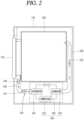
- the clothes treating apparatus having a drying function of the present embodiment may be configured as a so-called a circulating dryer" in which air exhausted from the drum 120 is reintroduced into the drum 120.
- lint in the air exhausted from the drum 120 may be reduced.
- the base 160 may include, for example, a bottom surface 162, two side surface parts 164 extending upwardly from both sides of the bottom surface 162, and a cover plate 162 disposed above the both side surface parts 164.
- the aforementioned lint filter installation part 140 is disposed in a front region of the base 160, and an guiding part 167 may be installed at a front surface end portion of the base 160 and connected to communicate with the lint filter installation part 140 to guide air, which has passed through the lint filter installation part 140, toward the evaporator 187.
- surfaces of the wires 216 and 217 of the mesh part 215 may have a smaller (smooth) surface roughness value than the cut surface of the fin 190.
- the lint filter 210a may be arranged to be sloped with respect to a vertical direction Lv of the cabinet 110 so as to easily remove the collected lint, for example.
- a vertical central line LM of the mesh part 215 of the lint filter 210a has a preset tilt angle ⁇ with respect to the vertical direction Lv of the cabinet 110.
- the lint filter 210a is disposed such that a distance between an upper portion of the mesh part 215 and the evaporator 187 is smaller than an interval between a lower portion of the mesh part 215 and the evaporator 187.
- the lint filter 210a may be disposed such that the mesh part 215 has a tilt angle ⁇ equal to or greater than 2° with respect to the vertical direction Lv of the cabinet 110.
- the tilt angle of the mesh part 215 with respect to the vertical direction Lv of the cabinet 110 of the lint filter 210a is less than 2°, performance of removing lint collected in the lint filter 210a may be relatively degraded.
- a process of collecting lint by the lint filter 210a will be described in detail with reference to FIG. 7 .
- the central portion of the lint 218 captured by the mesh part 215 is positioned on the upstream side of the mesh part 215 with respect to a flow direction of air and both end portions of the lint 218 are disposed on a downstream side of the mesh part 215, and thus, the central portion of the lint 218 is disposed on a lower side of the lint 218, relative to both end portions of the lint 218. Accordingly, when an external force acts downwardly on the lints 218 captured by the mesh part 215, the lints 218 may be easily separated from the wires 216 and 217.
- the evaporator 187 may have end plates 195 provided on both sides of the evaporator 187such that the linear sections 189a and/or the fins 190 are stably supported, while maintaining a preset interval therebetween.
- the lint filter 210a may include an evaporator coupling part 220 so as to be coupled to the evaporator 187.
- the evaporator coupling part 220 may be formed to detachably attach the lint filter 210a to the heat-exchanger 182.
- the lint filter 210a may have a length corresponding to a length of the evaporator 187.
- the length of the frame 212 of the lint filter 210a may correspond to (substantially equal to) a distance between end plates 195 of the evaporator 187.
- the lint filter 210a may have a length that allows the bent parts 197 of the end plates 195 to be disposed on both sides of the frame 212 of the lint filter 210a.
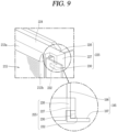
- the evaporator coupling part 220 may include a hook 225 that is in contact with both ends of the evaporator 187.
- the lint filter 210a may be provided with a hook support part 224 supporting the hook 225.
- the hook support part 224 may have a long plate shape that is bent backward from an upper end of the frame 212 of the lint filter 210a and extends horizontally, for example.
- the hooks 225 may be provided at both ends of the hook support part 224.
- each of the hooks 225 may include a horizontal section 226 and a vertical section 227.
- the horizontal section 226 may extend from both ends of the hook support part 224 in a horizontal direction along a longitudinal direction.
- the vertical section 227 may be bent downward from an end portion of the horizontal section 226 so that an inner surface of the vertical section 227 may contact the end plate 195.
- an inner surface of the vertical section 227 may be in contact with an outer surface of the end plate 195 so that the lint filter 210a is prevented from moving along the longitudinal direction of the evaporator 187.
- the hook 225 may be configured to be coupled to the end plate 195 with slight interference, for example.
- a distance (width) between the vertical sections 227 of the hook 225 may be slightly smaller than a distance between outer surfaces of the end plates 195.
- the hook 225 may expand outward due to an elastic force of the hook 225 so as to be coupled to the outer surface of the end plate 195.
- a coupling force between the lint filter 210a and the evaporator 187 is increased, so that a coupled state of the lint filter 210a and the evaporator 187 may be stably maintained.
- a movement of the evaporator 187 along a left-right direction may be prevented.
- the lint filter 210a is fixed with respect to the left-right direction of the evaporator 187, generation of vibrations due to a movement of the lint filter 210a in the left-right direction may be restrained when air exhausted from the drum 120 circulates.
- Each of the hooks 225 may be in contact with the bent part 197 of the end plate 195 to prevent movement of the lint filter 210a in a thickness direction of the evaporator 87.
- each of the hooks 225 may include a contact protrusion 230 contacting the rear surface of the bent part 197.
- the contact protrusion 230 may protrude from the vertical section 227.
- a guide slope 232 formed to be sloped upward forward may be provided on one side of the contact protrusion 230.
- the guide slope 232 guides the contact protrusion 230 to be brought into contact with the bent part 197 of the end plate 195 and move to a rear surface of the bent part 197.
- the bent part 197 of the end plate 195 and the contact protrusion 230 are in contact with each other, increasing a coupling force therebetween to restrain generation of a movement.
- the lint filter 210a is fixed in a forward/backward direction, when during air exhausted from the drum 120 circulates to flow, generation of vibrations of the lint filter 210a in the forward/backward direction due to a gap along the forward/backward direction of the lint filter 210a may be suppressed.
- a coupling force between the hook 225 and the end plate 195 is further increased so that generation of a gap between the contact protrusion 230 and the bending part 197 in a forward/backward direction may be significantly reduced.
- the spray tube 250a for spraying water to the lint filter 210a may be provided on one side of the lint filter 210a in order to separate lint collected in the lint filter 210a.
- the spray tube 250a may be provided on an upper and outer side of the base 160.
- An outlet of the spray tube 250a may be inserted into the cover plate 165, for example.
- Each of the spray tubes 250a may have a diffuser 252.
- the diffuser 252 may be formed such that a flow cross-sectional area increases toward an outlet along a movement direction of water.
- a guide plate 255 for guiding water may be provided in the outlet region of the diffuser 252.
- the guide plate 255 may be sloped downward to guide water toward a front upper portion of the lint filter 210a.
- water which has passed through the outlet of the spray tube 250a is guided to the front surface (upper portion) of the lint filter 210a and flows downward along the mesh part 215 of the lint filter 210a to wash out the lint 218 collected in the mesh part 215 to separate and remove the lint 218 from the mesh part 215.
- the plurality of spry tubes 250a may be spaced apart from each other in a longitudinal direction of the lint filter 210a and respectively provided in the mesh parts 215 of the lint filter 210a.
- three spray tubes 250a are provided and respectively disposed in the three mesh parts 215, and here, the number of the mesh parts 215 and the number of spray tubes 250a may be appropriately adjusted.
- a water supply part 260 supplying water to the spray tube 250a may be provided on one side of the spray tube 250a.
- the water supply part 260 may be configured to supply condensate water generated in the evaporator 187 to the spray tube 250a.
- the water supply part 260 may include, for example, a pump 265 pumping the condensate water and a pump connection part 267 connected to the spray tube 250a at one side and to the pump 265 at the other side.
- the drain pipe 285 may be configured to be connected to, for example, a condensate water storage tank (not shown) storing condensate water.
- the lint collecting part 310 may be disposed such that a portion (rear end portion) of the bottom part 312 thereof adjacent to the lint filter 210a is higher than the front surface side (front end portion).
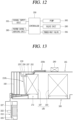
- the control unit 350 may be implemented as a microprocessor having a control program, for example.
- air inside the drum 120 may be moved to the circulation flow channel 130.
- Air which has been heat-exchanged to have a reduced water content may be brought into contact with the condenser 183 so as to be heat-exchanged.
- the control unit 350 may control the pump 265 on the basis of a signal input from the signal input unit 355 to supply water to the spray tube 250a.
- control unit 350 may control the valve unit 280 so that water may be sequentially supplied to each spray tube250a.
- the water supplied to the spray tube 250a is reduced in speed through the diffuser 252 and flow thereof may be stabilized.
- the water supplied to the upper portion of the front surface of the lint filter 210a comes into contact with the mesh part 215 of the lint filter 210a to wash the mesh part 215.
- the mesh part 215 is disposed to be sloped with respect to a vertical direction of the evaporator 187, so that water in contact with the mesh part 215 moves downward along the slope of the mesh part 215 to easily remove the lint 218 captured by the mesh part 215.
- the lint 218 collected in the mesh part 215 is arranged in a state in which a portion of an upstream side (central portion of the lint 218) faces downward, compared with portions of a downstream side (both end portions of the lint 218), and thus, when the lint 218 comes into contact with water falling along the slope of the upstream side of the mesh part 215, the lint 215 may be easily separated and dropped.
- control unit 350 may control the 3-way valve 295 so that water from the water supply source 292 is supplied to the valve unit 292
- control unit 350 may control the 3-way valve 295 to stop water supply from the water supply source 292 and control the pump 265 to resume supply of the condensate water.
- the lint dropped together with the lint filter 210a from the lint filter 210a may be collected by the lint collector 310.
- the water dropped to the bottom part 312 of the lint collecting part 310 may pass through the bottom part 312 and may be temporarily stored in the condensate water collecting part 172 and subsequently moved to the condensate water storage 174.
- the lint dropped to the bottom part 312 of the lint collecting part 310 may be restrained from passing through the mesh part 332 of the bottom part 312 and collected on the bottom part 312.
- the lint collected on the bottom part 312 of the lint collecting part 310 may be moved to a front region of the bottom part 312 by the slope of the bottom part 312.
- the lint collected in the lint collecting part 310 may be removed through the lint collecting part opening 118.
- the lint of the lint collecting part 310 may be separated and removed from the lint collecting part 310 after the lint collecting part 310 is taken out of the cabinet 110 through the lint collecting part opening 118.
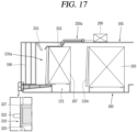
- FIGS. 13 to 17 Another embodiment of the present disclosure will be described with reference to FIGS. 13 to 17 .
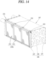
- the clothes treating apparatus having a drying function of this embodiment includes a cabinet 110, a drum 120 installed inside the cabinet 110, a heat-exchanger 182 heat-exchanged with air exhausted from the drum 120, a lint filter 210b disposed on an upstream side of the heat-exchanger 182 with respect to flow of air exhausted from the drum 120 to collect lint in the air, a spray tube 250b spraying water to the lint filter 210b to separate the lint collected in the lint filter 210b from the lint filter 21 0b, and a lint collecting unit having at least a portion provided below the lint filter 210b or below the heat-exchanger 182 to collect falling lint.
- the drum 120 is rotatably installed within the cabinet 110 and a base 120 forming part of a circulation flow channel 130 of air exhausted from the drum 120 may be provided below the drum 120.
- the evaporator 187 and the condenser 183 may be provided within the base 160 along an air flow direction.
- a lint filter 210b may be provided on the upstream side of the evaporator 187 to collect lint in the air.
- the lint filter 210b of this embodiment includes a frame 212 forming at least one opening 214 and a mesh part 215 provided in the opening 214 to allow air to pass therethrough and to suppress passage of the lint.
- a vertical center line LM of the mesh part 215 of the lint filter 210b may be disposed at a slope angle ( ⁇ ) previously set with respect to a vertical direction of the cabinet 110.
- a distance between an upper portion of the mesh part 215 and the evaporator 187 may be larger than a distance between a lower portion of the mesh part 215 and the evaporator 187.
- the lint filter 210b may be disposed at a slope angle ( ⁇ ) of 2 degrees or greater with respect to the vertical direction Lv of the cabinet 110.
- the lint filter 210b may include a spacer 219 that maintains a gap between the frame 212 and the evaporator 187.
- the spacer 219 may protrude from the frame 212 of the lint filter 210b toward the evaporator 187.
- the spacer 219 may be provided at an upper end portion of the frame 212 of the lint filter 210b.
- the lint filter 210b may include an evaporator coupling part 220 so as to be coupled to the evaporator 187.
- the evaporator coupling part 220 may include a hook 225 coupled to end plates 195 on both sides of the evaporator 187.
- the hooks 225 may be configured to come into contact an outer surface of the end plate 195 of the evaporator 187 and a rear surface of the bent part 197, respectively.
- Water discharged from each spray tube 250b may be sprayed to a rear surface of the lint filter 210b.
- the outlet of the diffuser 252 may be the first spray part 256 and the second spray part 257 may be positioned on an upstream side of the outlet of the diffuser 252 along a flow direction of water of the spray tube 250b.
- the second spray part 257 may be formed to spray water to an upstream side end region of the evaporator 187 along a flow direction of air exhausted from the drum 120, for example.
- lint adhered to the upstream side end portion of the evaporator 187 through the lint filter 210b may be separated and removed.
- the lint collecting part 310 may include a bottom part 312 and a side wall part 315 extending upward from the edges of the bottom part 312.
- the water supplied to the spray tube 250b may be sprayed to the evaporator 187 and the lint filter 210b through the second spray part 257 and the first spray part 256, respectively.
- Part of the water sprayed to the rear surface of the lint filter 210b through the first spray part 256 may fall through the mesh part 215 of the lint filter 210b and the other part of the water may drop along the mesh part 215 to separate and remove the lint 218 coupled to the mesh part 215 of the lint filter 210b.
- the lint drops from the evaporator 187 and the lint filter 210b may be collected by the lint collecting part 310.
- the spray tube may include only the first spray part
Landscapes
- Engineering & Computer Science (AREA)
- Textile Engineering (AREA)
- Detail Structures Of Washing Machines And Dryers (AREA)
Priority Applications (1)
| Application Number | Priority Date | Filing Date | Title |
|---|---|---|---|
| EP25159271.3A EP4549648A3 (de) | 2015-06-18 | 2016-05-20 | Kleiderbehandlungsvorrichtung mit trocknungsfunktion |
Applications Claiming Priority (4)
| Application Number | Priority Date | Filing Date | Title |
|---|---|---|---|
| KR1020150086803A KR101718040B1 (ko) | 2015-06-18 | 2015-06-18 | 건조기능을 구비한 의류처리장치 |
| EP16811827.1A EP3312334B1 (de) | 2015-06-18 | 2016-05-20 | Kleidungsbehandlungsvorrichtung mit trocknungsfunktion |
| PCT/KR2016/005401 WO2016204414A1 (ko) | 2015-06-18 | 2016-05-20 | 건조기능을 구비한 의류처리장치 |
| EP19210027.9A EP3647480B1 (de) | 2015-06-18 | 2016-05-20 | Kleidungsbehandlungsvorrichtung mit trocknungsfunktion |
Related Parent Applications (3)
| Application Number | Title | Priority Date | Filing Date |
|---|---|---|---|
| EP19210027.9A Division-Into EP3647480B1 (de) | 2015-06-18 | 2016-05-20 | Kleidungsbehandlungsvorrichtung mit trocknungsfunktion |
| EP19210027.9A Division EP3647480B1 (de) | 2015-06-18 | 2016-05-20 | Kleidungsbehandlungsvorrichtung mit trocknungsfunktion |
| EP16811827.1A Division EP3312334B1 (de) | 2015-06-18 | 2016-05-20 | Kleidungsbehandlungsvorrichtung mit trocknungsfunktion |
Related Child Applications (1)
| Application Number | Title | Priority Date | Filing Date |
|---|---|---|---|
| EP25159271.3A Division EP4549648A3 (de) | 2015-06-18 | 2016-05-20 | Kleiderbehandlungsvorrichtung mit trocknungsfunktion |
Publications (2)
| Publication Number | Publication Date |
|---|---|
| EP4397805A2 true EP4397805A2 (de) | 2024-07-10 |
| EP4397805A3 EP4397805A3 (de) | 2024-10-02 |
Family
ID=57546560
Family Applications (5)
| Application Number | Title | Priority Date | Filing Date |
|---|---|---|---|
| EP19210029.5A Active EP3647481B1 (de) | 2015-06-18 | 2016-05-20 | Kleidungsbehandlungsvorrichtung mit trocknungsfunktion |
| EP19210027.9A Active EP3647480B1 (de) | 2015-06-18 | 2016-05-20 | Kleidungsbehandlungsvorrichtung mit trocknungsfunktion |
| EP24172889.8A Pending EP4397805A3 (de) | 2015-06-18 | 2016-05-20 | Kleiderbehandlungsvorrichtung mit trocknungsfunktion |
| EP25159271.3A Pending EP4549648A3 (de) | 2015-06-18 | 2016-05-20 | Kleiderbehandlungsvorrichtung mit trocknungsfunktion |
| EP16811827.1A Active EP3312334B1 (de) | 2015-06-18 | 2016-05-20 | Kleidungsbehandlungsvorrichtung mit trocknungsfunktion |
Family Applications Before (2)
| Application Number | Title | Priority Date | Filing Date |
|---|---|---|---|
| EP19210029.5A Active EP3647481B1 (de) | 2015-06-18 | 2016-05-20 | Kleidungsbehandlungsvorrichtung mit trocknungsfunktion |
| EP19210027.9A Active EP3647480B1 (de) | 2015-06-18 | 2016-05-20 | Kleidungsbehandlungsvorrichtung mit trocknungsfunktion |
Family Applications After (2)
| Application Number | Title | Priority Date | Filing Date |
|---|---|---|---|
| EP25159271.3A Pending EP4549648A3 (de) | 2015-06-18 | 2016-05-20 | Kleiderbehandlungsvorrichtung mit trocknungsfunktion |
| EP16811827.1A Active EP3312334B1 (de) | 2015-06-18 | 2016-05-20 | Kleidungsbehandlungsvorrichtung mit trocknungsfunktion |
Country Status (6)
| Country | Link |
|---|---|
| US (6) | US10815610B2 (de) |
| EP (5) | EP3647481B1 (de) |
| KR (1) | KR101718040B1 (de) |
| ES (1) | ES2839454T3 (de) |
| PL (1) | PL3647481T3 (de) |
| WO (1) | WO2016204414A1 (de) |
Families Citing this family (37)
| Publication number | Priority date | Publication date | Assignee | Title |
|---|---|---|---|---|
| KR101718040B1 (ko) * | 2015-06-18 | 2017-03-20 | 엘지전자 주식회사 | 건조기능을 구비한 의류처리장치 |
| US10557469B2 (en) | 2016-03-22 | 2020-02-11 | Whirlpool Corporation | Multi-outlet fluid flow system for an appliance incorporating a bi-directional motor |
| US10087569B2 (en) | 2016-08-10 | 2018-10-02 | Whirlpool Corporation | Maintenance free dryer having multiple self-cleaning lint filters |
| US10738411B2 (en) | 2016-10-14 | 2020-08-11 | Whirlpool Corporation | Filterless air-handling system for a heat pump laundry appliance |
| US10655266B2 (en) | 2016-11-30 | 2020-05-19 | Whirlpool Corporation | Lint processing fluid pump for a laundry appliance |
| US10480117B2 (en) | 2017-02-27 | 2019-11-19 | Whirlpool Corporation | Self cleaning sump cover |
| US10619289B2 (en) * | 2017-02-27 | 2020-04-14 | Whirlpool Corporation | Self cleaning diverter valve |
| US10544539B2 (en) | 2017-02-27 | 2020-01-28 | Whirlpool Corporation | Heat exchanger filter for self lint cleaning system in dryer appliance |
| US10662574B2 (en) | 2017-02-27 | 2020-05-26 | Whirlpool Corporation | Self cleaning heater exchanger plate |
| US10634412B2 (en) | 2017-04-10 | 2020-04-28 | Whirlpool Corporation | Concealed upstream air tower guide vanes |
| US11015281B2 (en) | 2017-09-26 | 2021-05-25 | Whirlpool Corporation | Laundry appliance having a maintenance free lint removal system |
| US10697700B2 (en) | 2018-01-17 | 2020-06-30 | Whirlpool Corporation | Refrigeration water dispensing system |
| EP3743552B1 (de) * | 2018-01-26 | 2025-11-12 | Electrolux Professional AB (publ) | Wäschetrockner |
| EP3791016B1 (de) * | 2018-05-08 | 2025-06-25 | V-Zug AG | Wäschetrockner |
| AU2018422381A1 (en) * | 2018-05-08 | 2020-10-29 | V-Zug Ag | Method for operating a washer-dryer |
| KR102627700B1 (ko) | 2018-08-20 | 2024-01-23 | 삼성전자주식회사 | 의류관리기 |
| US11230806B2 (en) | 2018-12-28 | 2022-01-25 | Whirlpool Corporation | Fabric treating appliance with pelletizer |
| IT201900001819A1 (it) * | 2019-02-08 | 2020-08-08 | Candy Spa | Macchina asciugabiancheria e filtro per lanugine |
| KR20200098115A (ko) * | 2019-02-12 | 2020-08-20 | 삼성전자주식회사 | 건조기 |
| US11352736B2 (en) | 2019-07-15 | 2022-06-07 | Lg Electronics Inc. | Laundry processing apparatus |
| WO2021029556A1 (ko) * | 2019-08-14 | 2021-02-18 | 엘지전자 주식회사 | 열교환기 및 상기 열교환기를 포함하는 가전제품의 제조방법 |
| GB2576859B (en) * | 2019-12-10 | 2021-03-03 | Inheriting Earth Ltd | Microplastic compactor and method of compacting microplastics |
| KR102845070B1 (ko) * | 2019-12-17 | 2025-08-13 | 엘지전자 주식회사 | 의류처리장치 및 의류처리장치의 제어방법 |
| KR102840722B1 (ko) * | 2019-12-17 | 2025-07-31 | 엘지전자 주식회사 | 의류처리장치 및 의류처리장치의 제어방법 |
| KR102845071B1 (ko) * | 2019-12-17 | 2025-08-13 | 엘지전자 주식회사 | 의류처리장치 및 의류처리장치의 제어방법 |
| KR102838127B1 (ko) * | 2019-12-20 | 2025-07-25 | 삼성전자주식회사 | 의류 건조기 |
| KR102838593B1 (ko) * | 2020-02-13 | 2025-07-25 | 엘지전자 주식회사 | 의류 처리장치 |
| US11452964B2 (en) * | 2020-03-04 | 2022-09-27 | Whirlpool Corporation | Water spray feature of an appliance for separating particulate material from a filter member |
| KR102805587B1 (ko) * | 2020-03-09 | 2025-05-14 | 엘지전자 주식회사 | 의류처리장치 및 그 제어방법 |
| KR102834307B1 (ko) * | 2020-07-29 | 2025-07-16 | 엘지전자 주식회사 | 의류처리장치 |
| US11319661B1 (en) * | 2020-12-22 | 2022-05-03 | Whirlpool Corporation | Ventilation solution for closed-loop dryer systems |
| KR20220114281A (ko) * | 2021-02-08 | 2022-08-17 | 엘지전자 주식회사 | 의류처리장치 |
| KR20220114275A (ko) * | 2021-02-08 | 2022-08-17 | 엘지전자 주식회사 | 의류처리장치 |
| CN116289126A (zh) * | 2021-12-21 | 2023-06-23 | 无锡小天鹅电器有限公司 | 用于烘干设备的底座组件及具有其的烘干设备 |
| USD1111270S1 (en) * | 2022-12-08 | 2026-02-03 | Lg Electronics Inc. | Dryer for clothing |
| KR20250121835A (ko) * | 2024-02-05 | 2025-08-12 | 엘지전자 주식회사 | 의류 처리장치 |
| KR20250171955A (ko) * | 2024-05-31 | 2025-12-09 | 엘지전자 주식회사 | 의류처리장치 |
Family Cites Families (32)
| Publication number | Priority date | Publication date | Assignee | Title |
|---|---|---|---|---|
| JPS57195343A (en) * | 1981-05-26 | 1982-12-01 | Victor Co Of Japan Ltd | Manufacture of reproducing stylus of variation detection type for electrostatic capacity value |
| DE3147460A1 (de) * | 1981-12-01 | 1983-06-16 | Karl Dipl.-Phys. 4600 Dortmund Winter | "verfahren und vorrichtung zur trennung von fluessigen gemischen durch verdampfen und kondensieren" |
| DE4212965A1 (de) * | 1992-04-18 | 1993-10-21 | Bauknecht Hausgeraete | Kondenswäschetrockner |
| FR2711073B1 (fr) * | 1993-10-15 | 1995-11-17 | Esswein Sa | Dispositif de nettoyage pour filtre du circuit séchage par flux d'air chaud d'une machine, en particulier pour une machine lave-linge séchante ou pour un sèche-linge. |
| JP3519236B2 (ja) * | 1997-03-06 | 2004-04-12 | 東芝キヤリア株式会社 | 空気調和機の室内ユニット |
| IT1311305B1 (it) * | 1998-12-07 | 2002-03-12 | Lg Electronics Inc | Filtro per un condizionatore d'aria e dispositivo per il suo montaggio. |
| DE10135471A1 (de) * | 2001-07-20 | 2003-01-30 | Bsh Bosch Siemens Hausgeraete | Wäschetrockner mit herausnehmbarem Filter |
| US7089763B2 (en) * | 2002-02-25 | 2006-08-15 | Worldwide Water, L.L.C. | Portable, potable water recovery and dispensing apparatus |
| US7055262B2 (en) * | 2003-09-29 | 2006-06-06 | Self Propelled Research And Development Specialists, Llc | Heat pump clothes dryer |
| US20050086832A1 (en) * | 2003-10-28 | 2005-04-28 | Michel Declos | Air heater |
| KR100700793B1 (ko) * | 2004-12-10 | 2007-03-27 | 엘지전자 주식회사 | 건조 겸용 세탁기의 린트 필터 어셈블리 |
| KR100664286B1 (ko) * | 2006-02-09 | 2007-01-04 | 엘지전자 주식회사 | 보조 응축 수단을 포함하는 의류 건조기 |
| WO2008043039A2 (en) * | 2006-10-04 | 2008-04-10 | The Regents Of The University Of California | Unified control of single and three-phase power converters |
| DE102006061211A1 (de) | 2006-12-22 | 2008-06-26 | BSH Bosch und Siemens Hausgeräte GmbH | Verfahren zum Entfernen von Flusen aus einem Wärmetauscher eines Hausgeräts, sowie entsprechendes Hausgerät |
| KR20080111765A (ko) * | 2007-06-19 | 2008-12-24 | 주식회사 대우일렉트로닉스 | 폐열회수 환기장치의 열교환기 |
| ITPN20070056A1 (it) | 2007-08-01 | 2009-02-02 | Imat S P A | "sistema di pulitura automatico di filtri ad aria e applicazione in una macchina asciugatrice" |
| KR100925739B1 (ko) * | 2007-09-13 | 2009-11-11 | 엘지전자 주식회사 | 덕트리스 건조기 |
| DE102007052835A1 (de) * | 2007-11-06 | 2009-05-07 | BSH Bosch und Siemens Hausgeräte GmbH | Verfahren und Vorrichtung zum Reinigen eines Bauteiles, insbesondere eines Verdampfers einer Kondensatoreinrichtung sowie Wasch- oder Wäschetrockner mit einer solchen Vorrichtung |
| DE102007060851A1 (de) * | 2007-12-18 | 2009-06-25 | BSH Bosch und Siemens Hausgeräte GmbH | Hausgerät zur Pflege von Wäschestücken und Verfahren zum Entfernen von Flusen |
| JP4992775B2 (ja) * | 2008-03-14 | 2012-08-08 | 株式会社デンソー | 車両用空調装置 |
| DE102008041998A1 (de) * | 2008-09-11 | 2010-03-18 | BSH Bosch und Siemens Hausgeräte GmbH | Trockner mit einem Flusenfilter und einer Reinigungsvorrichtung |
| DE102008054832A1 (de) * | 2008-12-17 | 2010-07-01 | BSH Bosch und Siemens Hausgeräte GmbH | Vorrichtung und Verfahren zum Reinigen eines in einem Prozess-luftkreislauf eines Wasch- oder Wäschetrockners angeordneten Bauteils |
| JP5474447B2 (ja) * | 2009-08-25 | 2014-04-16 | 株式会社神戸製鋼所 | 建設機械の冷却構造 |
| KR101704420B1 (ko) * | 2010-05-13 | 2017-02-09 | 삼성전자주식회사 | 의류 건조기 |
| EP2386679B1 (de) * | 2010-05-13 | 2020-07-01 | Samsung Electronics Co., Ltd. | Wäschetrockner |
| PL2478969T3 (pl) * | 2011-01-24 | 2017-08-31 | Electrolux Home Products Corporation N.V. | Urządzenie gospodarstwa domowego |
| RU2533712C1 (ru) * | 2011-03-29 | 2014-11-20 | ЭлДжи ЭЛЕКТРОНИКС ИНК. | Устройство обработки одежды, содержащее устройство очистки теплообменника |
| KR101825448B1 (ko) * | 2011-03-29 | 2018-02-05 | 엘지전자 주식회사 | 열교환기 세척노즐 및 그를 이용한 열교환기의 세척 장치 |
| US20130255097A1 (en) * | 2012-03-27 | 2013-10-03 | Bsh Bosch Und Siemens Hausgerate Gmbh | Clothes treatment appliance with condenser and cleaning device |
| EP2719819B1 (de) * | 2012-10-15 | 2017-02-01 | Electrolux Home Products Corporation N.V. | Wärmepumpenwäschetrockner |
| JP2014150997A (ja) * | 2013-02-08 | 2014-08-25 | Toshiba Corp | 洗濯乾燥機 |
| KR101718040B1 (ko) * | 2015-06-18 | 2017-03-20 | 엘지전자 주식회사 | 건조기능을 구비한 의류처리장치 |
-
2015
- 2015-06-18 KR KR1020150086803A patent/KR101718040B1/ko active Active
-
2016
- 2016-05-20 EP EP19210029.5A patent/EP3647481B1/de active Active
- 2016-05-20 US US15/737,154 patent/US10815610B2/en active Active
- 2016-05-20 ES ES16811827T patent/ES2839454T3/es active Active
- 2016-05-20 EP EP19210027.9A patent/EP3647480B1/de active Active
- 2016-05-20 EP EP24172889.8A patent/EP4397805A3/de active Pending
- 2016-05-20 EP EP25159271.3A patent/EP4549648A3/de active Pending
- 2016-05-20 PL PL19210029.5T patent/PL3647481T3/pl unknown
- 2016-05-20 EP EP16811827.1A patent/EP3312334B1/de active Active
- 2016-05-20 WO PCT/KR2016/005401 patent/WO2016204414A1/ko not_active Ceased
-
2020
- 2020-09-24 US US17/030,795 patent/US11421373B2/en active Active
- 2020-09-24 US US17/030,829 patent/US11326300B2/en active Active
-
2022
- 2022-07-15 US US17/865,702 patent/US11932984B2/en active Active
-
2024
- 2024-02-12 US US18/439,228 patent/US20240183100A1/en active Pending
-
2025
- 2025-10-09 US US19/354,171 patent/US20260035853A1/en active Pending
Also Published As
| Publication number | Publication date |
|---|---|
| EP4549648A2 (de) | 2025-05-07 |
| US10815610B2 (en) | 2020-10-27 |
| EP4549648A3 (de) | 2025-07-16 |
| EP3647480A1 (de) | 2020-05-06 |
| EP3647480B1 (de) | 2024-07-03 |
| EP3647481A1 (de) | 2020-05-06 |
| ES2839454T3 (es) | 2021-07-05 |
| PL3647481T3 (pl) | 2023-05-15 |
| WO2016204414A1 (ko) | 2016-12-22 |
| EP3647481B1 (de) | 2023-03-15 |
| US20260035853A1 (en) | 2026-02-05 |
| KR101718040B1 (ko) | 2017-03-20 |
| US20180171537A1 (en) | 2018-06-21 |
| US20220349113A1 (en) | 2022-11-03 |
| US20210010197A1 (en) | 2021-01-14 |
| EP3312334B1 (de) | 2020-12-02 |
| US11932984B2 (en) | 2024-03-19 |
| EP3312334A1 (de) | 2018-04-25 |
| US11326300B2 (en) | 2022-05-10 |
| EP3312334A4 (de) | 2019-02-20 |
| US20240183100A1 (en) | 2024-06-06 |
| EP4397805A3 (de) | 2024-10-02 |
| US11421373B2 (en) | 2022-08-23 |
| US20210010196A1 (en) | 2021-01-14 |
| KR20160149593A (ko) | 2016-12-28 |
Similar Documents
| Publication | Publication Date | Title |
|---|---|---|
| US11932984B2 (en) | Clothes treating apparatus having drying function | |
| EP3124681B1 (de) | Wäschebehandlungsvorrichtung | |
| US9249538B2 (en) | Laundry treatment apparatus with heat pump | |
| EP2565322B1 (de) | Steuerverfahren für einen trockner | |
| EP3040470B1 (de) | Vorrichtung zur behandlung von kleidungsstücken | |
| US7024795B2 (en) | Drying apparatus | |
| AU2016385263B2 (en) | Clothes treating apparatus | |
| EP2549007B1 (de) | Wärmepumpenvorrichtung zur Wäschebehandlung | |
| EP4324977B1 (de) | Verfahren zum betrieb einer trocknungsvorrichtung mit einer wärmepumpe und einer reinigungsvorrichtung | |
| KR20210010143A (ko) | 의류처리장치 | |
| US11421374B2 (en) | Dryer |
Legal Events
| Date | Code | Title | Description |
|---|---|---|---|
| PUAI | Public reference made under article 153(3) epc to a published international application that has entered the european phase |
Free format text: ORIGINAL CODE: 0009012 |
|
| STAA | Information on the status of an ep patent application or granted ep patent |
Free format text: STATUS: REQUEST FOR EXAMINATION WAS MADE |
|
| 17P | Request for examination filed |
Effective date: 20240529 |
|
| AC | Divisional application: reference to earlier application |
Ref document number: 3312334 Country of ref document: EP Kind code of ref document: P Ref document number: 3647480 Country of ref document: EP Kind code of ref document: P |
|
| AK | Designated contracting states |
Kind code of ref document: A2 Designated state(s): AL AT BE BG CH CY CZ DE DK EE ES FI FR GB GR HR HU IE IS IT LI LT LU LV MC MK MT NL NO PL PT RO RS SE SI SK SM TR |
|
| PUAL | Search report despatched |
Free format text: ORIGINAL CODE: 0009013 |
|
| AK | Designated contracting states |
Kind code of ref document: A3 Designated state(s): AL AT BE BG CH CY CZ DE DK EE ES FI FR GB GR HR HU IE IS IT LI LT LU LV MC MK MT NL NO PL PT RO RS SE SI SK SM TR |
|
| RIC1 | Information provided on ipc code assigned before grant |
Ipc: D06F 58/20 20060101ALN20240828BHEP Ipc: D06F 58/24 20060101AFI20240828BHEP |
|
| GRAP | Despatch of communication of intention to grant a patent |
Free format text: ORIGINAL CODE: EPIDOSNIGR1 |
|
| STAA | Information on the status of an ep patent application or granted ep patent |
Free format text: STATUS: GRANT OF PATENT IS INTENDED |