EP4397906A1 - Réseau de microlentilles et accessoire de lampe de véhicule utilisant un réseau de microlentilles - Google Patents
Réseau de microlentilles et accessoire de lampe de véhicule utilisant un réseau de microlentilles Download PDFInfo
- Publication number
- EP4397906A1 EP4397906A1 EP22864223.7A EP22864223A EP4397906A1 EP 4397906 A1 EP4397906 A1 EP 4397906A1 EP 22864223 A EP22864223 A EP 22864223A EP 4397906 A1 EP4397906 A1 EP 4397906A1
- Authority
- EP
- European Patent Office
- Prior art keywords
- side lens
- emission
- lens portion
- microlens array
- incidence
- Prior art date
- Legal status (The legal status is an assumption and is not a legal conclusion. Google has not performed a legal analysis and makes no representation as to the accuracy of the status listed.)
- Withdrawn
Links
Images






Classifications
-
- F—MECHANICAL ENGINEERING; LIGHTING; HEATING; WEAPONS; BLASTING
- F21—LIGHTING
- F21S—NON-PORTABLE LIGHTING DEVICES; SYSTEMS THEREOF; VEHICLE LIGHTING DEVICES SPECIALLY ADAPTED FOR VEHICLE EXTERIORS
- F21S41/00—Illuminating devices specially adapted for vehicle exteriors, e.g. headlamps
- F21S41/20—Illuminating devices specially adapted for vehicle exteriors, e.g. headlamps characterised by refractors, transparent cover plates, light guides or filters
- F21S41/25—Projection lenses
- F21S41/265—Composite lenses; Lenses with a patch-like shape
-
- F—MECHANICAL ENGINEERING; LIGHTING; HEATING; WEAPONS; BLASTING
- F21—LIGHTING
- F21S—NON-PORTABLE LIGHTING DEVICES; SYSTEMS THEREOF; VEHICLE LIGHTING DEVICES SPECIALLY ADAPTED FOR VEHICLE EXTERIORS
- F21S41/00—Illuminating devices specially adapted for vehicle exteriors, e.g. headlamps
- F21S41/10—Illuminating devices specially adapted for vehicle exteriors, e.g. headlamps characterised by the light source
- F21S41/14—Illuminating devices specially adapted for vehicle exteriors, e.g. headlamps characterised by the light source characterised by the type of light source
- F21S41/141—Light emitting diodes [LED]
- F21S41/143—Light emitting diodes [LED] the main emission direction of the LED being parallel to the optical axis of the illuminating device
-
- F—MECHANICAL ENGINEERING; LIGHTING; HEATING; WEAPONS; BLASTING
- F21—LIGHTING
- F21S—NON-PORTABLE LIGHTING DEVICES; SYSTEMS THEREOF; VEHICLE LIGHTING DEVICES SPECIALLY ADAPTED FOR VEHICLE EXTERIORS
- F21S41/00—Illuminating devices specially adapted for vehicle exteriors, e.g. headlamps
- F21S41/10—Illuminating devices specially adapted for vehicle exteriors, e.g. headlamps characterised by the light source
- F21S41/14—Illuminating devices specially adapted for vehicle exteriors, e.g. headlamps characterised by the light source characterised by the type of light source
- F21S41/141—Light emitting diodes [LED]
- F21S41/151—Light emitting diodes [LED] arranged in one or more lines
-
- F—MECHANICAL ENGINEERING; LIGHTING; HEATING; WEAPONS; BLASTING
- F21—LIGHTING
- F21S—NON-PORTABLE LIGHTING DEVICES; SYSTEMS THEREOF; VEHICLE LIGHTING DEVICES SPECIALLY ADAPTED FOR VEHICLE EXTERIORS
- F21S41/00—Illuminating devices specially adapted for vehicle exteriors, e.g. headlamps
- F21S41/20—Illuminating devices specially adapted for vehicle exteriors, e.g. headlamps characterised by refractors, transparent cover plates, light guides or filters
- F21S41/25—Projection lenses
- F21S41/275—Lens surfaces, e.g. coatings or surface structures
-
- G—PHYSICS
- G02—OPTICS
- G02B—OPTICAL ELEMENTS, SYSTEMS OR APPARATUS
- G02B3/00—Simple or compound lenses
- G02B3/0006—Arrays
- G02B3/0037—Arrays characterized by the distribution or form of lenses
- G02B3/0056—Arrays characterized by the distribution or form of lenses arranged along two different directions in a plane, e.g. honeycomb arrangement of lenses
-
- F—MECHANICAL ENGINEERING; LIGHTING; HEATING; WEAPONS; BLASTING
- F21—LIGHTING
- F21S—NON-PORTABLE LIGHTING DEVICES; SYSTEMS THEREOF; VEHICLE LIGHTING DEVICES SPECIALLY ADAPTED FOR VEHICLE EXTERIORS
- F21S41/00—Illuminating devices specially adapted for vehicle exteriors, e.g. headlamps
- F21S41/30—Illuminating devices specially adapted for vehicle exteriors, e.g. headlamps characterised by reflectors
- F21S41/32—Optical layout thereof
- F21S41/322—Optical layout thereof the reflector using total internal reflection
Definitions
- Patent Literature 1 a vehicle lamp for irradiating forward of the lamp via a microlens array is known.
- the present disclosure is intended to provide a microlens array that reduces an occurrence of glare while increasing utilization efficiency of light, and a vehicle lamp using the microlens array.
- the microlens array according to Patent Literature 1 is configured to effectively condense light that has passed through an inside of the microlens array and to project a light distribution pattern.
- a microlens array of a new configuration is needed.
- a microlens array according to a first aspect of the present disclosure is a microlens array including a plurality of optical systems, in which
- a microlens array according to a third aspect of the present disclosure is a microlens array including a plurality of optical systems, in which
- a vehicle lamp according to a fourth aspect of the present disclosure includes:
- microlens array that diffuses emitted light more widely, and a vehicle lamp using the microlens array.
- the “up-down direction” is a direction including an “up direction” and a “down direction”.
- the “front-back direction” is a direction including a “front direction” and a “back direction”.
- the “left-right direction” is a direction including a "left direction” and a “right direction”.
- the reference sign U shown in the drawings described below indicates the up direction.
- the reference sign D indicates the down direction.
- the reference sign F indicates the front direction.
- the reference sign B indicates the back direction.
- the reference sign L indicates the left direction.
- the reference sign R indicates the right direction. Note that it cannot be said that these directions coincide with the respective directions set for a vehicle in a state in which a microlens array and a vehicle lamp are attached to the vehicle.
- a light source 5, a primary lens 6, and a microlens array 7 are provided in the lamp chamber 4.
- the light source 5 is arranged facing toward the front direction in a state of being mounted on a substrate 501 supported by the housing 3.
- a light emitting diode (LED) or a laser diode (LD) can be used as the light source 5, for example.
- the light emitted from the light source 5 passes through the primary lens 6 and the microlens array 7 and is emitted in the front direction of the vehicle lamp 1.
- a virtual straight line extending from a center point of a light emitting surface of the light source 5 in the front-back direction of the vehicle lamp 1 is referred to as a main optical axis Mx of the vehicle lamp 1.
- the primary lens 6 converts the light emitted from the light source 5 into parallel light and causes the parallel light to be incident on the microlens array 7.
- a collimating lens, an aplanat lens, a Fresnel lens, or the like can be used as the primary lens 6, a collimating lens, an aplanat lens, a Fresnel lens, or the like can be used.
- the primary lens 6 shown in FIG. 1 has a first incidence portion 61 provided at a position facing the light source 5, and a second incidence portion 62 provided as a vertical wall surrounding the first incidence portion 61.
- Light B1 incident on the first incidence portion 61 from the light source 5 is refracted on the first incidence portion 61, for example, in order to be parallel light to the main optical axis Mx.
- Light B2 incident on the second incidence portion 62 from the light source 5 is reflected by a reflective surface 63 in order to be parallel light to the main optical axis Mx.
- one light source unit is configured by the light source 5, the primary lens 6 and the microlens array 7.
- the vehicle lamp 1 may include a plurality of light source units in the same light chamber 4.
- the microlens array 7 is an optical component formed of, for example, a transparent resin material or a glass material.
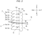
- FIG. 2 is a cross-sectional view of the microlens array 7 of FIG. 1 , seen in the right direction.
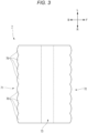
- FIG. 3 is a cross-sectional view of the microlens array 7 of FIG. 1 , seen in the up direction.
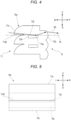
- FIG. 4 is a partial enlarged view of the microlens array 7 of FIG. 2 .
- FIG. 5 is a schematic view of an optical system 70a of the microlens array 7 of FIG. 4 , seen from an incidence-side lens portion 71 side.
- the microlens array 7 has a plurality of optical systems 70.
- the respective optical systems 70 are adjacent in a direction orthogonal to an emission direction of light (main optical axis Mx: optical axis Ax of the incidence-side lens portion 71), and the respective optical systems 70 are integrated.
- the plurality of optical systems 70 are arranged adjacent to each other in the up-down direction and the left-right direction.
- the respective optical systems 70 have the same shape and dimension as each other.
- the size of the optical system 70 is arbitrary, but is preferably about 0.5 to 10 mm square, and more preferably about 0.5 to 5 mm square, in a front view of an irradiation direction.
- a thickness of the optical system 70 in the front-back direction is preferably 3 mm to 40 mm.
- Each of the optical systems 70 includes a pair of an incidence-side lens portion 71 and an emission-side lens portion 72, and a low refractive index portion 73.
- the optical system 70a includes a portion including an incidence surface 71a of the incidence-side lens portion 71, a portion including an emission surface 72a of the emission-side lens portion 72, and a low refractive index portion 73a.
- the optical systems 70b to 70f are also the same.
- the low refractive index portion 73 has a first surface 731 extending through a focus f of the emission-side lens portion 72, and a second surface 732 extending from the first surface 731 toward the incident surface of the incidence-side lens portion 71.
- a cut line forming portion is formed by a boundary portion 733 between the first surface 731 and the second surface 732.
- the cut line forming portion forms a cut line in a light distribution pattern that is formed by the vehicle lamp 1.
- the first surface 731 is a surface extending in the up-down direction and the left-right direction.
- the second surface 732 is a surface extending in the front-back direction and the left-right direction.
- the second surface 732 is configured, for example, to totally reflect light incident from the corresponding incidence-side lens portion 71 and reaching the second surface 732.
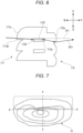
- the lower surface 71aE of the incident surface 71a of the incidence-side lens portion 71 is located above the second surface 732, as shown in FIG. 4 . That is, since there is no portion of the incident surface 71a located below the second surface 732, the light incident on the low refractive index portion 73 from the side surface 734 of the low refractive index portion 73 is considerably reduced. In other words, most of the light incident on the incidence-side lens portion 71 is directly incident on the emission-side lens portion 72, or is reflected on the second surface 732 of the low refractive index portion 73 and is then incident on the emission-side lens portion 72 (light B5 in FIG. 4 ). As a result, the occurrence of glare can be suppressed, and as shown in FIG. 8 , a light distribution pattern P2 having a desired shape including a cut line can be formed by the vehicle lamp 1 having the microlens array 7.
- the emission surface of the emission-side lens portion 72 forms a curved surface with a single radius of curvature whether seen in the left-right direction or the up-down direction.
- an emission surface of an emission-side lens portion 72A may have a first region 721 and a second region 722 with different radii of curvature.
- FIG. 10 is a schematic diagram of the emission-side lens portion 72A of FIG. 9 seen from the emission-side lens portion 72A side.
- a boundary line BL dividing the first region 721 and the second region 722 is a line extending in the left-right direction, and the first region 721 is located above the second region 722.
- the first region 721 and the second region 722 are divided so that the optical axis Ax of the emission-side lens portion 72A passes through the boundary line BL.
- the first region 721 is formed to form a curved surface with a single radius of curvature when seen in the up-down direction, as shown in FIG. 3 .
- the second region 722 is also formed to form a curved surface with a single radius of curvature when seen in the up-down direction, as shown in FIG. 3 .
- emission-side lens portion 72A may be applied to all the emission-side lens portions 72 constituting the microlens array 7, or may be applied to some of the emission-side lens portions 72.
- the emission-side lens portion 72A may be applied to the emission-side lens portion 72, which is paired with the incidence-side lens portion 71 having a configuration that diffuses light with a large radius of curvature of the incident surface.
- the configuration of the emission-side lens portion 72A shown in FIG. 9 can also be applied to an optical system having a configuration other than the optical system 70 in FIG. 2 .
- the configuration of the emission-side lens portion 72A can also be applied to an optical system in which the lower surface of the incident surface is located on the same level as or below the second surface 732 of the low refractive index portion 73.
- each of the optical systems 70 includes a pair of an incidence-side lens portion 71 and an emission-side lens portion 72, and a low refractive index portion 73.
- the optical system 70a includes a portion including an incidence surface 71a of the incidence-side lens portion 71, a portion including an emission surface 72a of the emission-side lens portion 72, and a low refractive index portion 73a.
- the optical systems 70b to 70f are also the same.
- the incidence-side lens portion 71 is provided on the primary lens 6 side with respect to the low refractive index portion 73.
- the emission-side lens portion 72 is provided on the outer cover 2 side with respect to the low refractive index portion 73.
- the incidence-side lens portion 71 and the emission-side lens portion 72 are provided on the common optical axis Ax and face each other.
- the optical axis Ax of each of the optical systems 70 is parallel to the main optical axis Mx of the vehicle lamp 1.
- the incidence-side lens portion 71 and the emission-side lens portion 72 each have a convex lens shape. In the shown microlens array 7, the respective optical systems 70 have the same shape and dimension as each other. Note that a focal length of the emission-side lens portion 72 is equal to or less than a lens thickness D of the incidence-side lens portion 71.
- the refractive index portion 73 has a first surface 731 extending through a focus f of the emission-side lens portion 72, and a second surface 732 extending from the first surface 731 toward the incident surface of the incidence-side lens portion 71.
- a cut line forming portion is formed by a boundary portion 733 between the first surface 731 and the second surface 732.
- the first surface 731 is a surface extending in the up-down direction and the left-right direction.
- the second surface 732 is a surface extending in the front-back direction and the left-right direction. The second surface 732 is configured, for example, to totally reflect light incident from the corresponding incidence-side lens portion 71 and reaching the second surface 732.
- Each of the optical systems 70 is formed so that a ratio A:B of a thickness A from the incident surface of the incidence-side lens portion 71 to the boundary portion 733 and a thickness B from the boundary portion 733 to the emission surface of the emission-side lens portion 72 is 1.8:1 or greater.
- a thickness refers to a thickness in a direction along the optical axis Ax (front-back direction in the example of FIG. 12 ). More specifically, the thickness A is a dimension from the most protruding portion of the incident surface of the incidence-side lens portion 71 to the boundary portion 733 on the optical axis Ax.
- the thickness B is a dimension from the boundary portion 733 to the most protruding portion of the emission surface of the emission-side lens portion 72 on the optical axis Ax.
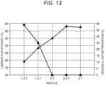
- FIG. 13 illustrates a relationship among a thickness ratio A:B of a lens portion of an optical system 70, a luminous flux efficiency, and a crosstalk light ray proportion.
- the horizontal axis indicates the ratio A:B.
- the vertical axis indicates the luminous flux efficiency and a crosstalk occurrence proportion.
- the black triangle indicates a value of the luminous flux efficiency, and the black circle indicates a value of the crosstalk light ray proportion.
- the crosstalk light ray proportion (%) indicates a ratio (so-called crosstalk occurrence proportion of light) of light incident on the incidence surface of the incidence-side lens portion 71 being incident on the emission surface of the not-paired next emission-side lens portion 72.
- the crosstalk light ray proportion (%) is calculated by ⁇ (C-P/2)/C ⁇ 100.
- the optical system 70 according to the present embodiment is formed so that the ratio A:B is 1.8:1 or greater. Therefore, it is possible to suppress the occurrence of crosstalk of light that part of the light incident from the incidence-side lens portion 71 is incident on the not-paired next emission-side lens portion 72 without being reflected on the second surface 732 of the low refractive index portion 73.
- the light incident from the incidence-side lens portion 71 and reflected on the second surface 732 of the low refractive index portion 73 can also be suppressed from being incident on the not-paired next emission-side lens portion 72. Therefore, the utilization efficiency of light can be increased.
- Each of the optical systems 41 has a pair of an incidence-side lens portion 42 and an emission-side lens portion 43, and a cavity portion 44, respectively.
- the incidence-side lens portion 42 is provided on the primary lens 6 side with respect to the cavity portion 44.
- the emission-side lens portion 43 is provided on the outer cover 2 side with respect to the cavity portion 44.
- the incidence-side lens portion 42 and the emission-side lens portion 43 face each other and have a common optical axis Ax2. Note that the optical axis Ax2 is parallel to the main optical axis Mx.
- the incident side lens portion 42 has a convex lens shape.
- the incidence-side lens portion 42 is configured to cause light incident through the primary lens 6 to be incident on the corresponding emission-side lens portion 43. Note that a focus of the incidence-side lens is preferably present in the vicinity of the cavity portion 44 described below.
- the cavity portion 44 has a first surface 41A and a second surface 44B.
- the first surface 44A is on a plane including the up-down direction and the left-right direction.
- the second surface 44B is on a plane including the front-back direction and the left-right direction.
- a cut line forming portion is formed by a boundary portion between the first surface 44A and the second surface 44B.
- the second surface 44B is preferably configured to totally reflect light incident from the corresponding incidence-side lens portion 42 and reaching the second surface 44B.
- the emission-side lens portion 43 emits light that passes through an inside of the optical system 41 and is incident on the emission-side lens portion 43 toward the outer cover 2 side.
- the emission surface forms a curved surface.
- the emission surface forms a flat surface.
- a microlens array constituted by the optical systems 41 in each of which when the emission surface of the emission-side lens portion 43 is seen in the left-right direction, the emission surface forms a curved surface, and when the emission surface of the emission-side lens portion 43 is seen in the up-down direction, the emission surface forms a flat surface may be referred to as a diffusion part 40.
- the light path when the diffusion part 40 is seen in the left-right direction will be described.
- light incident on the incident surface of the incidence-side lens portion 42 substantially in parallel to the main optical axis Mx and the optical axis Ax2 is refracted on the incident surface.
- Part of light L1 of the light refracted on the incident surface is totally reflected on the second surface 44B of the cavity portion 44 and travels toward the emission-side lens portion 43.
- the other light L2 refracted on the incident surface travels directly toward the emission-side lens portion 43.
- the light incident on the emission-side lens portion 43 is refracted on the emission surface of the emission-side lens portion 43.
- the light may travel toward an emission-side lens portion of a different optical system that does not correspond to the incidence-side lens portion 42 on which the light L 1 is incident.
- the light refracted on the emission surface of the emission-side lens portion and emitted may cause stray light without traveling in a desired direction. Since the microlens array 7 according to the present embodiment has the second surface 44B of the cavity portion 44, almost all of the light incident from the incidence-side lens portion 42 can be emitted from the corresponding emission-side lens portion 43, leading to a reduction in occurrence of stray light and an improvement in utilization efficiency of light.
- the cut line forming portion formed by the boundary portion between the first surface 44A and the second surface 44B of the cavity portion 44 favorably shields light that would be irradiated upward by refraction on the emission surface of the emission-side lens portion 43 if it is not reflected on the second surface 44B. For this reason, light that is irradiated upward in front of the vehicle lamp 1 and may cause glare to an oncoming vehicle is hardly generated.
- the emission surface of the emission-side lens portion 43 with respect to the optical system 41 constituting the diffusion part 40 forms a flat surface when seen in the up-down direction, which is the first direction, and forms a curved surface when seen in the left-right direction, which is the second direction.
- the emission surface of the emission-side lens portion 43 of the diffusion part 40 is a curved surface when seen in the left-right direction, the light emitted from the diffusion part 40 is likely to be condensed in the up-down direction.
- the emission surface of the emission-side lens portion 43 of the diffusion part 40 is a flat surface when seen in the up-down direction, the light emitted from the diffusion part 40 is likely to be diffused in the left-right direction.
- an irradiation range in the left-right direction is required to be wider than an irradiation range in the up-down direction. According to the vehicle lamp 1 of the present embodiment, it is easy to form a light distribution pattern with a wide irradiation range in the left-right direction.
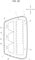
- FIG. 19 is a view of the emission-side lens portions 43, 53 of the plurality of optical systems 41, 51 constituting the microlens array 7, seen from the front. As shown in FIG. 19 , the diffusion parts 40 are surrounded by the light distribution forming parts 50. With this configuration, the microlens array 7 with high designability can be realized.
Landscapes
- Engineering & Computer Science (AREA)
- General Engineering & Computer Science (AREA)
- Physics & Mathematics (AREA)
- Optics & Photonics (AREA)
- Microelectronics & Electronic Packaging (AREA)
- General Physics & Mathematics (AREA)
- Non-Portable Lighting Devices Or Systems Thereof (AREA)
Applications Claiming Priority (4)
| Application Number | Priority Date | Filing Date | Title |
|---|---|---|---|
| JP2021139975 | 2021-08-30 | ||
| JP2021139973 | 2021-08-30 | ||
| JP2021139974 | 2021-08-30 | ||
| PCT/JP2022/030748 WO2023032638A1 (fr) | 2021-08-30 | 2022-08-12 | Réseau de microlentilles et accessoire de lampe de véhicule utilisant un réseau de microlentilles |
Publications (2)
| Publication Number | Publication Date |
|---|---|
| EP4397906A1 true EP4397906A1 (fr) | 2024-07-10 |
| EP4397906A4 EP4397906A4 (fr) | 2025-01-01 |
Family
ID=85412231
Family Applications (1)
| Application Number | Title | Priority Date | Filing Date |
|---|---|---|---|
| EP22864223.7A Withdrawn EP4397906A4 (fr) | 2021-08-30 | 2022-08-12 | Réseau de microlentilles et accessoire de lampe de véhicule utilisant un réseau de microlentilles |
Country Status (4)
| Country | Link |
|---|---|
| US (1) | US12352400B2 (fr) |
| EP (1) | EP4397906A4 (fr) |
| JP (1) | JP7791893B2 (fr) |
| WO (1) | WO2023032638A1 (fr) |
Families Citing this family (4)
| Publication number | Priority date | Publication date | Assignee | Title |
|---|---|---|---|---|
| JP2024169903A (ja) * | 2023-05-26 | 2024-12-06 | 株式会社小糸製作所 | 車両用灯具 |
| KR20250016818A (ko) * | 2023-07-26 | 2025-02-04 | 에스엘 주식회사 | 차량용 램프 |
| FR3157919A1 (fr) * | 2023-12-28 | 2025-07-04 | Valeo Vision | Module lumineux configuré pour la projection d’au moins un faisceau lumineux à coupure |
| WO2025154493A1 (fr) * | 2024-01-17 | 2025-07-24 | 株式会社小糸製作所 | Phare avant pour véhicule |
Family Cites Families (18)
| Publication number | Priority date | Publication date | Assignee | Title |
|---|---|---|---|---|
| JP2000330101A (ja) | 1999-05-20 | 2000-11-30 | Fujitsu General Ltd | 二重マイクロアレイレンズ付lcd |
| JP5200337B2 (ja) | 2006-06-09 | 2013-06-05 | パナソニック株式会社 | ディスプレイ装置 |
| JP6160116B2 (ja) | 2013-02-21 | 2017-07-12 | セイコーエプソン株式会社 | 照明装置、及びプロジェクター |
| AT514967B1 (de) * | 2013-10-25 | 2015-08-15 | Zizala Lichtsysteme Gmbh | Mikroprojektions-Lichtmodul für einen Kraftfahrzeugscheinwerfer |
| JP6201708B2 (ja) * | 2013-12-11 | 2017-09-27 | スタンレー電気株式会社 | 車両用灯具及びレンズ体 |
| JP6295854B2 (ja) * | 2014-06-24 | 2018-03-20 | スタンレー電気株式会社 | レンズ体、レンズ結合体及び車両用灯具 |
| JP6515525B2 (ja) * | 2014-12-22 | 2019-05-22 | スタンレー電気株式会社 | 灯具 |
| FR3055400B1 (fr) * | 2016-09-01 | 2019-06-28 | Valeo Vision | Module optique pour eclairer des points de portique |
| KR102171391B1 (ko) * | 2017-01-19 | 2020-10-29 | 하스코 비전 테크놀로지 컴퍼니 리미티드 | Adb 기능이 있는 led 광원 하이-로우 빔 일체형 차량용 램프 모듈 |
| KR102384541B1 (ko) | 2017-07-19 | 2022-04-11 | 에스엘 주식회사 | 차량용 램프 |
| US20190049648A1 (en) * | 2017-08-10 | 2019-02-14 | Valeo North America, Inc. | Lighting device with a diopter |
| KR102421071B1 (ko) * | 2017-12-27 | 2022-07-14 | 에스엘 주식회사 | 차량용 램프 |
| WO2020071413A1 (fr) | 2018-10-05 | 2020-04-09 | 株式会社小糸製作所 | Phare de véhicule |
| JP2020061231A (ja) * | 2018-10-05 | 2020-04-16 | 株式会社小糸製作所 | 車両用灯具 |
| KR102704123B1 (ko) * | 2019-11-01 | 2024-09-06 | 에스엘 주식회사 | 차량용 램프 |
| JP7532046B2 (ja) | 2020-03-03 | 2024-08-13 | キヤノン株式会社 | 撮像装置およびその制御方法、撮像システム |
| JP7423371B2 (ja) * | 2020-03-24 | 2024-01-29 | スタンレー電気株式会社 | 車両用灯具 |
| KR20230029346A (ko) * | 2021-08-24 | 2023-03-03 | 현대모비스 주식회사 | 차량용 램프 및 그 램프를 포함하는 차량 |
-
2022
- 2022-08-12 EP EP22864223.7A patent/EP4397906A4/fr not_active Withdrawn
- 2022-08-12 JP JP2023545411A patent/JP7791893B2/ja active Active
- 2022-08-12 WO PCT/JP2022/030748 patent/WO2023032638A1/fr not_active Ceased
- 2022-08-12 US US18/687,938 patent/US12352400B2/en active Active
Also Published As
| Publication number | Publication date |
|---|---|
| JP7791893B2 (ja) | 2025-12-24 |
| US12352400B2 (en) | 2025-07-08 |
| US20240426447A1 (en) | 2024-12-26 |
| WO2023032638A1 (fr) | 2023-03-09 |
| JPWO2023032638A1 (fr) | 2023-03-09 |
| EP4397906A4 (fr) | 2025-01-01 |
Similar Documents
| Publication | Publication Date | Title |
|---|---|---|
| EP4397906A1 (fr) | Réseau de microlentilles et accessoire de lampe de véhicule utilisant un réseau de microlentilles | |
| EP2993392B1 (fr) | Élément de lentille et unité d'éclairage de véhicule | |
| JP6595881B2 (ja) | 拡散配光光学系及び車両用灯具 | |
| JP6720809B2 (ja) | 導光部材、導光部材ユニットおよび照明装置 | |
| EP4419833B1 (fr) | Dispositif d'illumination pour un phare de vehicule | |
| JP6402260B2 (ja) | 光線シェード部材を有する照射装置 | |
| JP6560514B2 (ja) | 車両用灯具 | |
| KR102293083B1 (ko) | 자동차 헤드램프용 조명 장치 및 자동차 헤드램프 | |
| JP2019096614A (ja) | 車両用灯具 | |
| JP2017212037A (ja) | 車両用前照灯 | |
| CN114729737A (zh) | 车辆用导光体以及车辆用灯具单元 | |
| EP3974877A1 (fr) | Corps de guidage de lumière de véhicule et unité de lampe de véhicule | |
| CN115807921A (zh) | 用于车辆的灯具及包含其的车辆 | |
| CN110998175A (zh) | 车辆用灯具 | |
| JP5445049B2 (ja) | 車両用灯具 | |
| US11054102B2 (en) | Collimator lens, light radiation device, and vehicle lighting apparatus | |
| JP5446757B2 (ja) | 車両用灯具 | |
| US10941917B2 (en) | Lighting tool for vehicle | |
| JP6052599B2 (ja) | 車両用前照灯 | |
| CN117881921A (zh) | 微透镜阵列以及使用微透镜阵列的车辆用灯具 | |
| JP5397174B2 (ja) | 車両用灯具 | |
| EP4180710B1 (fr) | Dispositif d'éclairage pour un phare de véhicule automobile | |
| JP2025073088A (ja) | 自動車投光器用の照射装置並びに自動車投光器 | |
| JP2025512000A (ja) | 光学素子、車用ライトモジュール、車用ライト及び車両 | |
| JP5135644B2 (ja) | 車両灯具用レンズ及び車両用前照灯 |
Legal Events
| Date | Code | Title | Description |
|---|---|---|---|
| STAA | Information on the status of an ep patent application or granted ep patent |
Free format text: STATUS: THE INTERNATIONAL PUBLICATION HAS BEEN MADE |
|
| PUAI | Public reference made under article 153(3) epc to a published international application that has entered the european phase |
Free format text: ORIGINAL CODE: 0009012 |
|
| STAA | Information on the status of an ep patent application or granted ep patent |
Free format text: STATUS: REQUEST FOR EXAMINATION WAS MADE |
|
| 17P | Request for examination filed |
Effective date: 20240227 |
|
| AK | Designated contracting states |
Kind code of ref document: A1 Designated state(s): AL AT BE BG CH CY CZ DE DK EE ES FI FR GB GR HR HU IE IS IT LI LT LU LV MC MK MT NL NO PL PT RO RS SE SI SK SM TR |
|
| REG | Reference to a national code |
Ref country code: DE Ref legal event code: R079 Free format text: PREVIOUS MAIN CLASS: F21Y0115100000 Ipc: F21S0041143000 |
|
| DAV | Request for validation of the european patent (deleted) | ||
| DAX | Request for extension of the european patent (deleted) | ||
| A4 | Supplementary search report drawn up and despatched |
Effective date: 20241203 |
|
| RIC1 | Information provided on ipc code assigned before grant |
Ipc: G02B 3/00 20060101ALI20241128BHEP Ipc: F21S 41/275 20180101ALI20241128BHEP Ipc: F21S 41/265 20180101ALI20241128BHEP Ipc: F21S 41/143 20180101AFI20241128BHEP |
|
| STAA | Information on the status of an ep patent application or granted ep patent |
Free format text: STATUS: THE APPLICATION HAS BEEN WITHDRAWN |
|
| 18W | Application withdrawn |
Effective date: 20250617 |