EP4397942A1 - Procédé et appareil de mesure de distance d'obstacle, et véhicule et support - Google Patents
Procédé et appareil de mesure de distance d'obstacle, et véhicule et support Download PDFInfo
- Publication number
- EP4397942A1 EP4397942A1 EP23825347.0A EP23825347A EP4397942A1 EP 4397942 A1 EP4397942 A1 EP 4397942A1 EP 23825347 A EP23825347 A EP 23825347A EP 4397942 A1 EP4397942 A1 EP 4397942A1
- Authority
- EP
- European Patent Office
- Prior art keywords
- light beam
- spot
- obstacle
- light
- vehicle
- Prior art date
- Legal status (The legal status is an assumption and is not a legal conclusion. Google has not performed a legal analysis and makes no representation as to the accuracy of the status listed.)
- Pending
Links
Images



Classifications
-
- G—PHYSICS
- G06—COMPUTING OR CALCULATING; COUNTING
- G06V—IMAGE OR VIDEO RECOGNITION OR UNDERSTANDING
- G06V20/00—Scenes; Scene-specific elements
- G06V20/50—Context or environment of the image
- G06V20/56—Context or environment of the image exterior to a vehicle by using sensors mounted on the vehicle
- G06V20/58—Recognition of moving objects or obstacles, e.g. vehicles or pedestrians; Recognition of traffic objects, e.g. traffic signs, traffic lights or roads
-
- G—PHYSICS
- G01—MEASURING; TESTING
- G01S—RADIO DIRECTION-FINDING; RADIO NAVIGATION; DETERMINING DISTANCE OR VELOCITY BY USE OF RADIO WAVES; LOCATING OR PRESENCE-DETECTING BY USE OF THE REFLECTION OR RERADIATION OF RADIO WAVES; ANALOGOUS ARRANGEMENTS USING OTHER WAVES
- G01S7/00—Details of systems according to groups G01S13/00, G01S15/00, G01S17/00
- G01S7/48—Details of systems according to groups G01S13/00, G01S15/00, G01S17/00 of systems according to group G01S17/00
- G01S7/483—Details of pulse systems
- G01S7/484—Transmitters
-
- G—PHYSICS
- G01—MEASURING; TESTING
- G01B—MEASURING LENGTH, THICKNESS OR SIMILAR LINEAR DIMENSIONS; MEASURING ANGLES; MEASURING AREAS; MEASURING IRREGULARITIES OF SURFACES OR CONTOURS
- G01B11/00—Measuring arrangements characterised by the use of optical techniques
- G01B11/02—Measuring arrangements characterised by the use of optical techniques for measuring length, width or thickness
- G01B11/026—Measuring arrangements characterised by the use of optical techniques for measuring length, width or thickness by measuring distance between sensor and object
-
- G—PHYSICS
- G01—MEASURING; TESTING
- G01S—RADIO DIRECTION-FINDING; RADIO NAVIGATION; DETERMINING DISTANCE OR VELOCITY BY USE OF RADIO WAVES; LOCATING OR PRESENCE-DETECTING BY USE OF THE REFLECTION OR RERADIATION OF RADIO WAVES; ANALOGOUS ARRANGEMENTS USING OTHER WAVES
- G01S11/00—Systems for determining distance or velocity not using reflection or reradiation
- G01S11/12—Systems for determining distance or velocity not using reflection or reradiation using electromagnetic waves other than radio waves
-
- G—PHYSICS
- G01—MEASURING; TESTING
- G01S—RADIO DIRECTION-FINDING; RADIO NAVIGATION; DETERMINING DISTANCE OR VELOCITY BY USE OF RADIO WAVES; LOCATING OR PRESENCE-DETECTING BY USE OF THE REFLECTION OR RERADIATION OF RADIO WAVES; ANALOGOUS ARRANGEMENTS USING OTHER WAVES
- G01S13/00—Systems using the reflection or reradiation of radio waves, e.g. radar systems; Analogous systems using reflection or reradiation of waves whose nature or wavelength is irrelevant or unspecified
- G01S13/86—Combinations of radar systems with non-radar systems, e.g. sonar, direction finder
- G01S13/867—Combination of radar systems with cameras
-
- G—PHYSICS
- G01—MEASURING; TESTING
- G01S—RADIO DIRECTION-FINDING; RADIO NAVIGATION; DETERMINING DISTANCE OR VELOCITY BY USE OF RADIO WAVES; LOCATING OR PRESENCE-DETECTING BY USE OF THE REFLECTION OR RERADIATION OF RADIO WAVES; ANALOGOUS ARRANGEMENTS USING OTHER WAVES
- G01S17/00—Systems using the reflection or reradiation of electromagnetic waves other than radio waves, e.g. lidar systems
- G01S17/86—Combinations of lidar systems with systems other than lidar, radar or sonar, e.g. with direction finders
-
- G—PHYSICS
- G01—MEASURING; TESTING
- G01S—RADIO DIRECTION-FINDING; RADIO NAVIGATION; DETERMINING DISTANCE OR VELOCITY BY USE OF RADIO WAVES; LOCATING OR PRESENCE-DETECTING BY USE OF THE REFLECTION OR RERADIATION OF RADIO WAVES; ANALOGOUS ARRANGEMENTS USING OTHER WAVES
- G01S17/00—Systems using the reflection or reradiation of electromagnetic waves other than radio waves, e.g. lidar systems
- G01S17/88—Lidar systems specially adapted for specific applications
- G01S17/93—Lidar systems specially adapted for specific applications for anti-collision purposes
- G01S17/931—Lidar systems specially adapted for specific applications for anti-collision purposes of land vehicles
-
- G—PHYSICS
- G01—MEASURING; TESTING
- G01S—RADIO DIRECTION-FINDING; RADIO NAVIGATION; DETERMINING DISTANCE OR VELOCITY BY USE OF RADIO WAVES; LOCATING OR PRESENCE-DETECTING BY USE OF THE REFLECTION OR RERADIATION OF RADIO WAVES; ANALOGOUS ARRANGEMENTS USING OTHER WAVES
- G01S7/00—Details of systems according to groups G01S13/00, G01S15/00, G01S17/00
- G01S7/48—Details of systems according to groups G01S13/00, G01S15/00, G01S17/00 of systems according to group G01S17/00
- G01S7/497—Means for monitoring or calibrating
-
- G—PHYSICS
- G06—COMPUTING OR CALCULATING; COUNTING
- G06T—IMAGE DATA PROCESSING OR GENERATION, IN GENERAL
- G06T7/00—Image analysis
- G06T7/70—Determining position or orientation of objects or cameras
-
- B—PERFORMING OPERATIONS; TRANSPORTING
- B60—VEHICLES IN GENERAL
- B60W—CONJOINT CONTROL OF VEHICLE SUB-UNITS OF DIFFERENT TYPE OR DIFFERENT FUNCTION; CONTROL SYSTEMS SPECIALLY ADAPTED FOR HYBRID VEHICLES; ROAD VEHICLE DRIVE CONTROL SYSTEMS FOR PURPOSES NOT RELATED TO THE CONTROL OF A PARTICULAR SUB-UNIT
- B60W2420/00—Indexing codes relating to the type of sensors based on the principle of their operation
- B60W2420/40—Photo, light or radio wave sensitive means, e.g. infrared sensors
- B60W2420/403—Image sensing, e.g. optical camera
-
- B—PERFORMING OPERATIONS; TRANSPORTING
- B60—VEHICLES IN GENERAL
- B60W—CONJOINT CONTROL OF VEHICLE SUB-UNITS OF DIFFERENT TYPE OR DIFFERENT FUNCTION; CONTROL SYSTEMS SPECIALLY ADAPTED FOR HYBRID VEHICLES; ROAD VEHICLE DRIVE CONTROL SYSTEMS FOR PURPOSES NOT RELATED TO THE CONTROL OF A PARTICULAR SUB-UNIT
- B60W2420/00—Indexing codes relating to the type of sensors based on the principle of their operation
- B60W2420/40—Photo, light or radio wave sensitive means, e.g. infrared sensors
- B60W2420/408—Radar; Laser, e.g. lidar
Definitions
- the pure visual perception technology is used for ranging, an obstacle in an image is identified according to a preset obstacle type, and a distance of the obstacle is determined according to the image, but the pure visual perception technology has the problem of not being able to achieve the intelligent tracking and accurate ranging. Therefore, an external apparatus such as an ultrasonic radar is required to be equipped in the related art, however, the external apparatus such as the ultrasonic radar cannot perform the intelligent tracking and accurate ranging based on the specific obstacle. Besides, the detection distance is limited.
- the light spot focusing chip is configured to adjust a light spot focusing parameter of a light beam spot.
- a computer-readable storage medium stores a computer instruction, and the computer instruction is configured to implement, when executed by a processor, the obstacle ranging method in any one of the embodiments of the present application.
- a picture in the driving direction of the vehicle may be collected according to a camera equipped on the vehicle, and may be transmitted in the form of a video through a bus or the like.
- the video may be decomposed into each frame of picture, and each frame of picture may be used as the first driving image captured by the camera.
- the first driving image is analyzed, when an object, such as an object having a height, different from environment features appears in the first driving image and blocks the driving direction, it may be understood that an obstacle exists in the driving direction, and the obstacle may be considered by default to have a ranging requirement.
- a range of the obstacle and the contour of the obstacle are marked in the first driving image, and the marked image is used as the obstacle region information of the obstacle.
- a light beam emission manner is determined according to a current vehicle speed and the obstacle region information.
- the current vehicle speed may be understood as the current driving speed of the vehicle.
- the light beam emission manner may be understood as different angles of light beam emission, where the light beam may be a light beam emitted by an infrared lamp, and the like.
- the light beam emitted by the infrared lamp is only used as an example for the light beam, and the light beam is not limited in the present application.
- a vehicle speed acquisition instruction may be sent to the corresponding sensor, and the current vehicle speed sent by the corresponding sensor may be received.
- the current vehicle speed may be compared with a preset speed threshold.
- the preset speed threshold it may be considered that the vehicle speed is relatively slow, the obstacle may be a pedestrian and the like. If the light beam emission angle is too high, it may be irradiated on human eyes and cause harm to pedestrians, the light beam may be emitted to the contour of the obstacle on the ground and controlled to track the contour of the obstacle.
- the light beam may be emitted at an included angle of 90° relative to the vehicle itself, that is, the light beam may be emitted parallel to the ground where the vehicle is located, so that the light beam may be irradiated on the surface of the obstacle, such as at the rear of the vehicle.
- the radio frequency rotation member may be controlled to rotate according to the light beam emission manner, a corresponding rotation angle instruction may be generated according to the light beam emission manner, and the rotation angle instruction is transmitted to the radio frequency rotation member so that the radio frequency rotation member rotates according to the corresponding angle and the left and right side radio frequency mechanisms are controlled to rotate to the corresponding angle to emit the light beam.
- the light beam emission manner may be emitting the light beam at an included angle of 90° relative to the vehicle itself.
- the radio frequency rotation member may be controlled to rotate the left and right side radio frequency mechanisms to an included angle of 90° with the ground so that light beams emitted by the left and right side radio frequency mechanisms may be irradiated on the surface of the obstacle.
- the light beam emission manner may be emitting the light beam on the left side at an included angle of 60° relative to the vehicle itself and emitting the light beam on the right side at an included angle of 30° relative to the vehicle itself.
- the radio frequency rotation member may be controlled to rotate the left side radio frequency mechanism to the included angle of 60° relative to the ground, and the radio frequency rotation member may be controlled to rotate the right side radio frequency mechanism to the included angle of 30° relative to the ground, so that the light beams emitted by the left and right side radio frequency mechanisms may be irradiated onto the contour of the obstacle on the ground.
- a light spot focusing parameter of a light beam spot is adjusted in a light spot focusing manner matching the light beam emission manner, and a second driving image containing the adjusted light beam spot is obtained.
- the light spot focusing manner may be understood as an adjustment manner of the light spot focusing parameter.
- the light beam spot is a light dropping point of the light beam in the emission direction of the light beam, that is, a spot presented when the light beam encounters the obstacle in the emission direction.
- the light spot focusing parameter may be understood as a parameter used for adjusting the light beam intensity and size.
- the second driving image may be understood as an image captured after the light spot focusing parameter of the light beam spot is adjusted.
- the left and right side radio frequency mechanisms only emit the light beam, and cannot adjust the light spot focusing parameter of the light beam. Therefore, a light spot focusing chip needs to be added to adjust the light spot focusing parameter of the light beam spot.
- the light spot focusing parameter may be adjusted through the light spot focusing chip in a form of a preset threshold.
- the parameter may be adjusted again through the light spot focusing chip. After the adjustment is completed, a second driving image that contains the adjusted light beam spot and is captured by the camera may be obtained.
- the spacing distance may be understood as a distance between the vehicle and the closest position of the obstacle to the vehicle.
- a size detection instruction may be sent to a preset light spot size detection unit.
- the light spot size detection unit may detect the light spot area in the second driving image periodically, light spot areas of two light spots on the left and right sides are acquired, and the light spot areas and the corresponding parameter are put into a preset first spacing distance formula to calculate a spacing distance between the vehicle and the obstacle.
- an angle detection instruction may be sent to a preset angle detection unit.
- the corresponding left and right side light spot areas are different, or the corresponding angles of the left and right side radio frequency mechanisms are different, then spacing distances on the left and right sides are different.
- a side with the closest spacing distance may be used as the spacing distance between the obstacle and the vehicle, alternatively, two spacing distances of the left and right sides of the vehicle relative to the obstacle may also be displayed simultaneously.
- the obstacle ranging method when it is determined, according to the captured first driving image, that the obstacle exists in the driving direction of the vehicle, the obstacle region information of the obstacle is determined; the light beam emission manner is determined according to the current vehicle speed and the obstacle region information; the left and right side radio frequency mechanisms on the vehicle are controlled to emit the light beam in the light beam emission manner; the light spot focusing parameter of the light beam spot is adjusted in the light spot focusing manner matching the light beam emission manner, and the second driving image containing the adjusted light beam spot is obtained; and the spacing distance between the vehicle and the obstacle is determined according to the second driving image.
- the light beam is emitted in the light beam emission manner and the light spot focusing manner which match the obstacle region information and the vehicle speed, the image containing the light beam spot is analyzed, and the spacing distance is determined.
- the intelligent tracking and accurate ranging of the obstacle are achieved based on the visual perception, and compared with the radar ranging method, the hardware architecture cost is reduced.
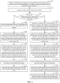
- FIG. 2 is a flowchart of an obstacle ranging method according to embodiment two of the present application. This embodiment is optimized based on the above-described embodiment. As shown in FIG. 2 , the method includes the following steps.
- FIG. 3 is an example diagram of a first driving image in the obstacle ranging method according to embodiment two of the present application, where a represents the vehicle, b represents the obstacle, and c represents a reference line.
- the obstacle region information of the obstacle may be determined according to the first driving image.
- an upper layer is the first driving image captured by a camera, the image includes an irregularly shaped obstacle b with calibrated contours and a reference line c obtained by connecting two points of the irregular obstacle which are closest to the vehicle a, so that the obstacle region information is obtained.
- a vehicle speed acquisition instruction may be sent to the corresponding sensor, and the current vehicle speed sent by the corresponding sensor may be received.
- the speed threshold may be understood as a threshold for determining whether the vehicle speed is too fast.
- the speed threshold may be preset.
- the current vehicle speed sent by the sensor is received, the current vehicle speed may be compared with the preset speed threshold to determine whether the current vehicle speed is greater than the preset speed threshold.
- a reference line corresponding to the obstacle is determined according to the obstacle region information, and a manner that a light spot dropping point corresponding to the light beam is located on the reference line is used as the light beam emission manner.
- the light spot dropping spot may be understood as a dropping point when the light spot is irradiated on the ground in the direction vertical to the vehicle head.
- the reference line may be understood as a straight line for identifying the contour of the obstacle projected on the ground.
- a region, where the obstacle is located, closest to the vehicle is identified as one straight line (namely, the shape of the obstacle is relatively regular) in the obstacle region information
- this straight line is used as the reference line
- a region, where the obstacle is located, closest to the vehicle is identified as dispersed points (that is, the shape of the obstacle is irregular) in the obstacle region information
- a tangent line of the obstacle region may be identified and used as the reference line, for example, two dispersed points closest to the vehicle among the dispersed points are found and connected to obtain the tangent line.
- the left and right side radio frequency mechanisms each have one light spot dropping point in the direction perpendicular to the vehicle head, and angles of the left and right side radio frequency mechanisms may be adjusted so that the two light spot dropping points may be on the straight line.
- the left and right side radio frequency mechanisms on the vehicle are controlled by a radio frequency rotation member to emit the light beam in the light beam emission manner that the light spot dropping point corresponding to the light beam is located on the reference line.
- the radio frequency rotation member is connected to the left and right side radio frequency mechanisms.
- the radio frequency rotation member may be controlled to rotate according to the light beam emission manner, the corresponding rotation angle instruction may be generated according to the light beam emission manner, and the rotation angle instruction is transmitted to the radio frequency rotation member so that the radio frequency rotation member rotates according to the corresponding angle and the left and right side radio frequency mechanisms are controlled to rotate to the corresponding angle to emit the light beam.
- the left and right side radio frequency mechanisms on the vehicle are controlled by the radio frequency rotation member to emit the light beam in the light beam emission manner of the included angle between the light beam and the vehicle being 90°.
- the radio frequency rotation member may be controlled to rotate according to the light beam emission manner, a rotation angle instruction corresponding to 90° may be generated according to the light beam emission manner, and the rotation angle instruction is transmitted to the radio frequency rotation member so that the radio frequency rotation member rotates according to the corresponding angle and the left and right side radio frequency mechanisms are controlled to rotate to 90° for emitting the light beam.
- the light spot focusing parameter may be adjusted according to the clarity of the light beam spot in the obstacle region information so that the light beam spot may be kept clearly displayed in the driving image, for example, the light spot focusing parameter may be adjusted in a form of a preset gear, and each gear corresponds to different light spot focusing parameters. Based on the clarity of the current light beam spot or the roughly calculated distance from the obstacle, a matching gear may be found, the light spot focusing parameter may be adjusted to the corresponding gear through the light spot focusing chip, that is, the light spot focusing parameter of the light beam spot may be adjusted to a target focusing parameter. After the adjustment is completed, the second driving image containing the adjusted light beam spot and captured by the camera may be obtained.
- the step in which the light spot focusing parameter of the light beam spot is adjusted and the second driving image containing the adjusted light beam spot is obtained may include the steps described below.
- spot clarity of the light beam spot in the obstacle region information is extracted.
- the obstacle region information in each frame may be acquired in real time.
- the obstacle region information may include the light beam spot, and the spot clarity of the light beam spot may be identified according to a preset method.
- the light spot focusing parameter is adjusted through the light spot focusing chip.
- the first spot clarity standard may be understood as a standard that the spot clarity needs to be achieved.
- the spot clarity may be compared with a preset first spot clarity standard.
- the spot clarity does not satisfy the preset first spot clarity standard, for example, each gear corresponds to a different light spot focusing parameter in the form of a preset gear
- a difference value between the current spot clarity and the first spot clarity standard or the roughly calculated distance from the obstacle is calculated to determine a gear where the difference value or the distance is located
- the light spot focusing parameter is adjusted to the corresponding gear through the light spot focusing chip, that is, the light spot focusing parameter of the light beam spot is adjusted so that the light beam spot may be clearly displayed in the driving image.
- the focusing parameter threshold may be understood as a parameter value that enables the light beam spot to be displayed.
- the light spot focusing parameter is adjusted through the light spot focusing chip based on the focusing parameter threshold.
- the second spot clarity standard may be understood as a standard that the spot clarity needs to be achieved.
- the second spot clarity standard is different from the first spot clarity standard.
- the second spot clarity standard may be lower than the first spot clarity standard.
- the spot clarity does not satisfy the preset first spot clarity standard, for example, when no light beam spot exists in the driving image, that is, the obstacle may be too far, the parameter may be adjusted again through the light spot focusing chip.
- each gear corresponds to a different light spot focusing parameter in the form of a preset gear
- a difference value between the current spot clarity and the second spot clarity standard or the roughly calculated distance from the obstacle may be calculated to determine a gear where the difference value or the distance is located, and the light spot focusing parameter is adjusted to the corresponding gear through the light spot focusing chip, that is, the light spot focusing parameter of the light beam spot is adjusted so that the light beam spot may be clearly displayed in the driving image.
- the installation height information may be understood as distances between the left and right side radio frequency mechanisms and the ground.
Landscapes
- Engineering & Computer Science (AREA)
- Physics & Mathematics (AREA)
- Radar, Positioning & Navigation (AREA)
- Remote Sensing (AREA)
- General Physics & Mathematics (AREA)
- Computer Networks & Wireless Communication (AREA)
- Electromagnetism (AREA)
- Theoretical Computer Science (AREA)
- Computer Vision & Pattern Recognition (AREA)
- Multimedia (AREA)
- Traffic Control Systems (AREA)
- Measurement Of Optical Distance (AREA)
Applications Claiming Priority (2)
| Application Number | Priority Date | Filing Date | Title |
|---|---|---|---|
| CN202211496847.4A CN115790420B (zh) | 2022-11-25 | 2022-11-25 | 障碍物测距方法、装置、车辆及介质 |
| PCT/CN2023/072290 WO2024108754A1 (fr) | 2022-11-25 | 2023-01-16 | Procédé et appareil de mesure de distance d'obstacle, et véhicule et support |
Publications (2)
| Publication Number | Publication Date |
|---|---|
| EP4397942A1 true EP4397942A1 (fr) | 2024-07-10 |
| EP4397942A4 EP4397942A4 (fr) | 2025-06-18 |
Family
ID=85441927
Family Applications (1)
| Application Number | Title | Priority Date | Filing Date |
|---|---|---|---|
| EP23825347.0A Pending EP4397942A4 (fr) | 2022-11-25 | 2023-01-16 | Procédé et appareil de mesure de distance d'obstacle, et véhicule et support |
Country Status (6)
| Country | Link |
|---|---|
| US (1) | US20250076027A1 (fr) |
| EP (1) | EP4397942A4 (fr) |
| JP (1) | JP7728372B2 (fr) |
| KR (1) | KR20240079191A (fr) |
| CN (1) | CN115790420B (fr) |
| WO (1) | WO2024108754A1 (fr) |
Families Citing this family (1)
| Publication number | Priority date | Publication date | Assignee | Title |
|---|---|---|---|---|
| CN116660901B (zh) * | 2023-04-23 | 2026-03-24 | 长城汽车股份有限公司 | 雷达控制方法、装置、车辆和计算机可读存储介质 |
Family Cites Families (19)
| Publication number | Priority date | Publication date | Assignee | Title |
|---|---|---|---|---|
| US4647193A (en) * | 1985-06-10 | 1987-03-03 | Rca Corporation | Optical target ranging apparatus |
| JP3690079B2 (ja) * | 1997-08-28 | 2005-08-31 | 日産自動車株式会社 | 車間距離警報装置 |
| DE102006007001B4 (de) * | 2006-02-15 | 2015-03-19 | Hella Kgaa Hueck & Co. | Vorrichtung zur Bestimmung des Abstandes zwischen einem Kraftfahrzeug und einem Hindernis |
| DE102007003024A1 (de) * | 2007-01-20 | 2008-07-31 | Sick Ag | Triangulationssensor mit Entfernungsbestimmung aus Lichtfleckposition und -form |
| KR101309028B1 (ko) * | 2010-12-29 | 2013-10-04 | 계명대학교 산학협력단 | 레이저 스캔 촛점을 이용한 거리 측정장치. |
| JP6314418B2 (ja) * | 2013-10-18 | 2018-04-25 | 株式会社デンソー | レーダ装置 |
| JP6386794B2 (ja) * | 2014-06-04 | 2018-09-05 | 日立建機株式会社 | 運搬車両 |
| WO2017200896A2 (fr) * | 2016-05-18 | 2017-11-23 | James O'keeffe | Lidar à orientation dynamique adapté à la forme de véhicule |
| CN106153000A (zh) * | 2016-06-17 | 2016-11-23 | 合肥工业大学 | 一种前方车辆距离检测方法 |
| CN106291520A (zh) * | 2016-07-14 | 2017-01-04 | 江苏大学 | 一种基于编码激光与双目视觉的辅助驾驶系统及方法 |
| US9869754B1 (en) * | 2017-03-22 | 2018-01-16 | Luminar Technologies, Inc. | Scan patterns for lidar systems |
| CN108323190B (zh) * | 2017-12-15 | 2022-07-29 | 深圳市道通智能航空技术股份有限公司 | 一种避障方法、装置和无人机 |
| CN108827434A (zh) * | 2018-05-18 | 2018-11-16 | 长沙开元仪器股份有限公司 | 一种煤样称量设备 |
| CN209344248U (zh) * | 2018-11-06 | 2019-09-03 | 江苏联赢激光有限公司 | 一种电芯称重装置 |
| CN110641366B (zh) * | 2019-10-12 | 2021-10-19 | 爱驰汽车有限公司 | 行车时的障碍物追踪方法、系统、电子设备和存储介质 |
| CN111103593B (zh) * | 2019-12-31 | 2025-05-16 | 深圳市欢创科技股份有限公司 | 测距模组、机器人、测距方法及非易失性可读存储介质 |
| JP7348881B2 (ja) * | 2020-06-10 | 2023-09-21 | 株式会社日立製作所 | 障害物検知システム、障害物検知方法および自己位置推定システム |
| CN112339653A (zh) * | 2020-10-21 | 2021-02-09 | 华域视觉科技(上海)有限公司 | 激光安全防护系统、激光安全防护方法和车辆 |
| CN113869268B (zh) * | 2021-10-12 | 2024-11-29 | 广州小鹏自动驾驶科技有限公司 | 障碍物测距方法、装置、电子设备及可读介质 |
-
2022
- 2022-11-25 CN CN202211496847.4A patent/CN115790420B/zh active Active
-
2023
- 2023-01-16 WO PCT/CN2023/072290 patent/WO2024108754A1/fr not_active Ceased
- 2023-01-16 KR KR1020237045435A patent/KR20240079191A/ko active Pending
- 2023-01-16 US US18/574,872 patent/US20250076027A1/en active Pending
- 2023-01-16 EP EP23825347.0A patent/EP4397942A4/fr active Pending
- 2023-01-16 JP JP2023581038A patent/JP7728372B2/ja active Active
Also Published As
| Publication number | Publication date |
|---|---|
| JP2025502895A (ja) | 2025-01-29 |
| WO2024108754A1 (fr) | 2024-05-30 |
| CN115790420B (zh) | 2026-03-03 |
| CN115790420A (zh) | 2023-03-14 |
| JP7728372B2 (ja) | 2025-08-22 |
| EP4397942A4 (fr) | 2025-06-18 |
| US20250076027A1 (en) | 2025-03-06 |
| KR20240079191A (ko) | 2024-06-04 |
Similar Documents
| Publication | Publication Date | Title |
|---|---|---|
| EP3566903A1 (fr) | Procédé et appareil de détection de position de véhicule | |
| CN112965504B (zh) | 基于自动驾驶的远程确认方法、装置、设备及存储介质 | |
| CN108202669B (zh) | 基于车车通信的不良天气视觉增强行车辅助系统及其方法 | |
| JP6453192B2 (ja) | 画像認識処理装置、及びプログラム | |
| CN113256739A (zh) | 车载bsd摄像头的自标定方法、设备和存储介质 | |
| EP3984010B1 (fr) | Systèmes et procédés de surveillance d'objet | |
| CN112639822B (zh) | 一种数据处理方法及装置 | |
| CN110341621B (zh) | 一种障碍物检测方法及装置 | |
| CN109840454B (zh) | 目标物定位方法、装置、存储介质以及设备 | |
| US11796331B2 (en) | Associating perceived and mapped lane edges for localization | |
| EP4397942A1 (fr) | Procédé et appareil de mesure de distance d'obstacle, et véhicule et support | |
| DE112019006281T5 (de) | Informationsverarbeitungsvorrichtung, informationsverarbeitungsverfahren und programm | |
| CN116679319B (zh) | 多传感器联合的隧道预警方法,系统,装置和存储介质 | |
| EP4086874A1 (fr) | Procédé et appareil de commande pour un véhicule intelligent, et dispositif associé | |
| CN110727269B (zh) | 车辆控制方法及相关产品 | |
| JP7647267B2 (ja) | 信号機認識装置 | |
| KR101844851B1 (ko) | 방향지시등 제어 기능을 갖는 블랙박스 및 이를 이용한 방향지시등 제어방법 | |
| KR102697664B1 (ko) | 차량의 차선 유지 장치 및 그 제어 방법 | |
| KR20190051464A (ko) | 자동 긴급 제동장치 및 그 제어방법 | |
| CN115359651A (zh) | 车辆盲区处理方法、装置、车载终端及存储介质 | |
| US20250304066A1 (en) | Vehicle control device | |
| US12422845B2 (en) | Vehicle control system, head-mounted display device, and vehicle control method | |
| CN112630788B (zh) | 一种环境障碍物位置信息检测方法及装置 | |
| KR20210006711A (ko) | 차량의 영상 기록 시스템 및 방법 | |
| JP2002202136A (ja) | 車両の周囲状況観測装置 |
Legal Events
| Date | Code | Title | Description |
|---|---|---|---|
| STAA | Information on the status of an ep patent application or granted ep patent |
Free format text: STATUS: UNKNOWN |
|
| STAA | Information on the status of an ep patent application or granted ep patent |
Free format text: STATUS: THE INTERNATIONAL PUBLICATION HAS BEEN MADE |
|
| PUAI | Public reference made under article 153(3) epc to a published international application that has entered the european phase |
Free format text: ORIGINAL CODE: 0009012 |
|
| STAA | Information on the status of an ep patent application or granted ep patent |
Free format text: STATUS: REQUEST FOR EXAMINATION WAS MADE |
|
| 17P | Request for examination filed |
Effective date: 20231228 |
|
| AK | Designated contracting states |
Kind code of ref document: A1 Designated state(s): AL AT BE BG CH CY CZ DE DK EE ES FI FR GB GR HR HU IE IS IT LI LT LU LV MC ME MK MT NL NO PL PT RO RS SE SI SK SM TR |
|
| A4 | Supplementary search report drawn up and despatched |
Effective date: 20250520 |
|
| RIC1 | Information provided on ipc code assigned before grant |
Ipc: G01S 13/86 20060101ALI20250514BHEP Ipc: G01S 13/93 20200101ALI20250514BHEP Ipc: G06V 20/58 20220101ALI20250514BHEP Ipc: G01B 11/14 20060101AFI20250514BHEP |
|
| DAV | Request for validation of the european patent (deleted) | ||
| DAX | Request for extension of the european patent (deleted) |