EP4397953A1 - Gassammelvorrichtung - Google Patents
Gassammelvorrichtung Download PDFInfo
- Publication number
- EP4397953A1 EP4397953A1 EP23843350.2A EP23843350A EP4397953A1 EP 4397953 A1 EP4397953 A1 EP 4397953A1 EP 23843350 A EP23843350 A EP 23843350A EP 4397953 A1 EP4397953 A1 EP 4397953A1
- Authority
- EP
- European Patent Office
- Prior art keywords
- gas
- jig
- battery
- gas collecting
- housing
- Prior art date
- Legal status (The legal status is an assumption and is not a legal conclusion. Google has not performed a legal analysis and makes no representation as to the accuracy of the status listed.)
- Granted
Links
Images


Classifications
-
- G—PHYSICS
- G01—MEASURING; TESTING
- G01N—INVESTIGATING OR ANALYSING MATERIALS BY DETERMINING THEIR CHEMICAL OR PHYSICAL PROPERTIES
- G01N1/00—Sampling; Preparing specimens for investigation
- G01N1/02—Devices for withdrawing samples
- G01N1/22—Devices for withdrawing samples in the gaseous state
-
- G—PHYSICS
- G01—MEASURING; TESTING
- G01N—INVESTIGATING OR ANALYSING MATERIALS BY DETERMINING THEIR CHEMICAL OR PHYSICAL PROPERTIES
- G01N1/00—Sampling; Preparing specimens for investigation
- G01N1/02—Devices for withdrawing samples
- G01N1/22—Devices for withdrawing samples in the gaseous state
- G01N1/2226—Sampling from a closed space, e.g. food package, head space
-
- G—PHYSICS
- G01—MEASURING; TESTING
- G01N—INVESTIGATING OR ANALYSING MATERIALS BY DETERMINING THEIR CHEMICAL OR PHYSICAL PROPERTIES
- G01N33/00—Investigating or analysing materials by specific methods not covered by groups G01N1/00 - G01N31/00
- G01N33/0004—Gaseous mixtures, e.g. polluted air
- G01N33/0009—General constructional details of gas analysers, e.g. portable test equipment
- G01N33/0011—Sample conditioning
- G01N33/0014—Sample conditioning by eliminating a gas
-
- G—PHYSICS
- G01—MEASURING; TESTING
- G01N—INVESTIGATING OR ANALYSING MATERIALS BY DETERMINING THEIR CHEMICAL OR PHYSICAL PROPERTIES
- G01N33/00—Investigating or analysing materials by specific methods not covered by groups G01N1/00 - G01N31/00
- G01N33/0004—Gaseous mixtures, e.g. polluted air
- G01N33/0009—General constructional details of gas analysers, e.g. portable test equipment
- G01N33/0011—Sample conditioning
- G01N33/0018—Sample conditioning by diluting a gas
-
- G—PHYSICS
- G01—MEASURING; TESTING
- G01N—INVESTIGATING OR ANALYSING MATERIALS BY DETERMINING THEIR CHEMICAL OR PHYSICAL PROPERTIES
- G01N33/00—Investigating or analysing materials by specific methods not covered by groups G01N1/00 - G01N31/00
- G01N33/0004—Gaseous mixtures, e.g. polluted air
- G01N33/0009—General constructional details of gas analysers, e.g. portable test equipment
- G01N33/0011—Sample conditioning
- G01N33/0019—Sample conditioning by preconcentration
-
- H—ELECTRICITY
- H01—ELECTRIC ELEMENTS
- H01M—PROCESSES OR MEANS, e.g. BATTERIES, FOR THE DIRECT CONVERSION OF CHEMICAL ENERGY INTO ELECTRICAL ENERGY
- H01M10/00—Secondary cells; Manufacture thereof
- H01M10/04—Construction or manufacture in general
- H01M10/0422—Cells or battery with cylindrical casing
-
- G—PHYSICS
- G01—MEASURING; TESTING
- G01N—INVESTIGATING OR ANALYSING MATERIALS BY DETERMINING THEIR CHEMICAL OR PHYSICAL PROPERTIES
- G01N1/00—Sampling; Preparing specimens for investigation
- G01N1/02—Devices for withdrawing samples
- G01N1/22—Devices for withdrawing samples in the gaseous state
- G01N1/2226—Sampling from a closed space, e.g. food package, head space
- G01N2001/2238—Sampling from a closed space, e.g. food package, head space the gas being compressed or pressurized
-
- G—PHYSICS
- G01—MEASURING; TESTING
- G01N—INVESTIGATING OR ANALYSING MATERIALS BY DETERMINING THEIR CHEMICAL OR PHYSICAL PROPERTIES
- G01N33/00—Investigating or analysing materials by specific methods not covered by groups G01N1/00 - G01N31/00
- G01N33/0004—Gaseous mixtures, e.g. polluted air
- G01N33/0009—General constructional details of gas analysers, e.g. portable test equipment
- G01N33/0011—Sample conditioning
- G01N33/0016—Sample conditioning by regulating a physical variable, e.g. pressure or temperature
-
- Y—GENERAL TAGGING OF NEW TECHNOLOGICAL DEVELOPMENTS; GENERAL TAGGING OF CROSS-SECTIONAL TECHNOLOGIES SPANNING OVER SEVERAL SECTIONS OF THE IPC; TECHNICAL SUBJECTS COVERED BY FORMER USPC CROSS-REFERENCE ART COLLECTIONS [XRACs] AND DIGESTS
- Y02—TECHNOLOGIES OR APPLICATIONS FOR MITIGATION OR ADAPTATION AGAINST CLIMATE CHANGE
- Y02E—REDUCTION OF GREENHOUSE GAS [GHG] EMISSIONS, RELATED TO ENERGY GENERATION, TRANSMISSION OR DISTRIBUTION
- Y02E60/00—Enabling technologies; Technologies with a potential or indirect contribution to GHG emissions mitigation
- Y02E60/10—Energy storage using batteries
Definitions
- the present disclosure relates to a gas collecting apparatus, and may be related to a gas collecting apparatus capable of collecting gas at an appropriate level of concentration for a battery having a case made of a rigid material of various specifications, in particular, a cylindrical battery.
- a secondary battery is a battery which can be used repeatedly through a discharging process in which chemical energy is converted into electrical energy and a charging process in the opposite direction to the discharging process and which includes nickel-cadmium (Ni-Cd) batteries, nickel-metal hydride (Ni-MH) batteries, lithium-metal batteries, lithium-ion (Li-ion) batteries, and lithium-ion polymer batteries.
- Ni-Cd nickel-cadmium
- Ni-MH nickel-metal hydride
- lithium-metal batteries lithium-ion batteries
- lithium-ion polymer batteries lithium-ion polymer batteries.
- lithium secondary batteries having high energy density and voltage, long cycle life, and a low self-discharge rate have been commercialized and widely used.
- the lithium secondary battery degrades while generating a large amount of gas due to electrolyte decomposition as repeated charging and discharging progresses, and this aspect appears differently depending on the design and use form of the battery. Therefore, it is essential to infer a deterioration mechanism of a battery by analyzing gas generated inside the battery during a battery development process.
- batteries are used in a wide range of industrial fields, and depending on various battery application environments and conditions, performance required for batteries also varies, and batteries can be designed in various specifications.
- the concentration of the gas delivered to an analyzer or stored in the gas collecting container varies greatly depending on the volume of the diffusion chamber, the size of the battery (material to be analyzed), and the amount of gas generated, which affects the analysis result.
- a means for adjusting the concentration of the gas delivered to the analyzer or the gas stored in the gas collecting container to a concentration optimized for analysis is required.
- the present disclosure relates to a gas collecting apparatus, and is to provide a gas collecting apparatus capable of collecting gas at an appropriate level of concentration for a battery having a case made of a rigid material of various specifications, in particular, a cylindrical battery.
- a gas collecting apparatus of the present disclosure may include
- a gas collecting apparatus of the present disclosure may have improved gas collection accuracy and convenience for an analyst by automating gas collection and high-concentration gas dilution.
- the gas collecting apparatus of the present disclosure maybe one in which batteries are easily installed, removed, or replaced when collecting gas.
- the gas collecting apparatus of the present disclosure may detect whether punching is completed by depth of a punching needle or an amount of pressure change to prevent a battery internal short circuit, thereby improving stability during gas collection.
- a gas collecting apparatus of the present disclosure may include
- the punching unit may include a punching needle which is inserted inside the outer housing through a needle insertion hole provided at the upper end of the outer housing, a lower end of the punching needle perforating the upper surface of the battery to form the perforated hole on the upper surface of the battery, a punching rod configured to move in the vertical direction by the punching driving unit, an upper end of the punching needle being coupled to a lower end of the punching rod, and a sealing cover configured to surround an outer circumferential surface of the punching rod, a lower end of the sealing cover being coupled to the upper end of the outer housing.
- the sealing cover may be provided as bellows extending or contracting in the vertical direction, an upper end of the sealing cover may be coupled to a moving member of the punching driving unit together with an upper end of the punching rod, and the lower end of the sealing cover may cover the needle insertion hole and be coupled to the upper end of the outer housing.
- the punching driving unit may include a moving member to which an upper end of the sealing cover and an upper end of the punching rod are fixed, a support member fixed to an outer circumferential surface of the outer housing, and a driving means fixed to the support member and configured to move the moving member in the vertical direction.
- the driving means may include a shaft extending in the vertical direction and provided with a screw thread on its outer circumferential surface, and a motor configured to rotate the shaft while being supported by the support member, wherein in the moving member, a shaft insertion hole into which the shaft is inserted is formed, and on an inner circumferential surface of the shaft insertion hole, a screw thread engaging with the screw thread of the shaft is formed.
- the outer housing may include an upper housing in which an upper end of the inner jig is accommodated, and a lower housing in which a lower end of the inner jig is accommodated, wherein on an upper surface of the upper housing, the needle insertion hole is formed, and the punching unit is coupled to the upper surface of the upper housing while covering the needle insertion hole from an outer side of the upper housing.
- the gas discharge pipe may be coupled to a side surface of the lower housing, in the upper jig, a first flow path configured to deliver gas discharged from an inside of the battery through the perforated hole and diffused inside the upper housing to the inside of the lower housing may be formed, and in the lower jig, a second flow path configured to deliver the gas delivered through the first flow path to the gas discharge pipe may be formed.
- an upper surface of the upper jig may be spaced apart from a ceiling surface at a predetermined interval inside the upper housing, the upper jig and the lower jig may be provided in a column shape extending in the vertical direction, the first flow path may be formed as a groove extending from an upper end to a lower end of the upper jig on an outer surface of the upper jig, and the second flow path may be formed as a groove extending from an upper end of the lower jig to a height at which the gas discharge pipe is connected to the lower housing on an outer surface of the lower jig.
- a gas collecting method using the gas collecting apparatus of the present disclosure may include
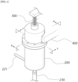
- FIG. 1 is a perspective view illustrating a gas collecting apparatus according of the present disclosure.
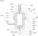
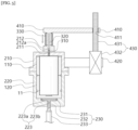
- FIG. 2 is a cross-sectional view illustrating a cross section A-A of FIG. 1 .
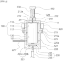
- FIG. 3 is a cross-sectional view illustrating a cross section B-B of FIG. 1 .
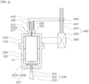
- FIG. 4 is a cross-sectional view illustrating an operation of a punching unit 300.
- FIG. 5 is a cross-sectional view illustrating separation of an inner jig 100.
- FIG. 6 is a perspective view illustrating the inner jig 100.
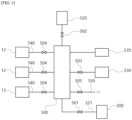
- FIG. 7 is a block diagram illustrating a gas collecting apparatus of the present disclosure.
- FIG. 8 is a block diagram illustrating a gas collecting method of the present disclosure.
- the battery to be a gas collecting target may be the cylindrical battery 11, and the inner jig 100 and the outer housing 200 may also be provided in a cylindrical shape.
- the punching needle 310 may be a rigid member having a sharp lower end.
- the punching needle 310 may be linearly movable in the upward and downward directions. When the punching needle 310 moves downward, the sharp lower end of the punching needle 310 may be inserted into the upper end of the battery 11 to form a perforated hole in the battery case.
- the lower end of the sealing cover 330 may be coupled to the upper end of the guide member 212, and more specifically, the lower end of the sealing cover 330 may be coupled to the upper end of the guide member 212 while covering the upper opening of the rod guide hole 212a.
- the sealing cover 330 may prevent gas inside and outside the outer housing 200 from being ventilated through the rod guide hole 212a.
- the punching driving unit 400 may include a moving member 410 to which an upper end of the sealing cover 330 and an upper end of the punching rod 320 are fixed, a support member 420 fixed to an outer circumferential surface of the outer housing 200, and a driving means 430 fixed to the support member 420 and configured to move the moving member 410 in the vertical direction.
- a space in which the lower end is opened is provided inside the upper housing 210, and a space in which the upper end of the lower housing 220 is opened is provided, and by the upper housing 210 and the lower housing 220 being coupled so that the lower end of the upper housing 210 and the upper end of the lower housing 220 contact each other, the two spaces may be formed as one closed space, and the inner jig 100 may be accommodated in the closed space.
- the upper housing 210 and the lower housing 220 may be provided in a cylindrical shape extending in the vertical direction.
- a ring-shaped first protrusion 215 protruding in the radial direction may be formed at the lower end of the outer circumferential surface of the upper housing 210
- a ring-shaped second protrusion 225 protruding in the radial direction may be formed at the upper end of the outer circumferential surface of the lower housing 220.
- the first protrusion 215 is provided with a plurality of first fixing holes 215a
- the second protrusion 225 is provided with a plurality of second fixing holes 225a
- a fixing member (not shown) may be simultaneously inserted into the first fixing hole 215a and the second fixing hole 225a to fix the coupling between the upper housing 210 and the lower housing 220.
- the fixing member may be a bolt provided with a screw thread, and a screw thread for screwing with the fixing member may be provided on an inner circumferential surface of the first fixing hole 215a or the second fixing hole 225a.
- the vertical length of the upper jig 110 may be longer than the vertical length of the inner space of the upper housing 210, and the vertical length of the lower jig 120 may be shorter than the vertical length of the inner space of the lower housing 220. Accordingly, the coupling portion between the upper jig 110 and the lower jig 120 may be located lower than the coupling portion between the upper housing 210 and the lower housing 220. Therefore, in the process of coupling the inner jig 100 to the outer housing 200, after the upper jig 110 and the lower jig 120 are simultaneously fixed to the lower housing 220, the upper housing 210 may be stably coupled to the upper end of the lower housing 220.
- a jig separator 230 for separating the lower jig 120 from the lower housing 220 may be provided at the lower end of the lower housing 220.
- the jig separator 230 may include a disk-shaped support plate 231 whose upper surface contacts the lower surface of the lower jig 120, a support bar 232 whose upper end is coupled to the lower surface of the support plate 231 and whose lower end protrudes to the outside of the lower housing 220 through a penetration hole 223 provided on the bottom surface of the lower housing 220, and a pneumatic cylinder 233 coupled to the lower end of the support bar 232 to move the support plate 231 and the support bar 232 in the vertical direction.
- the support plate 231 may be provided in a disk shape having a plane perpendicular to the vertical direction, and the support bar 232 may be provided in a bar shape extending in the vertical direction.
- the penetration hole 223 may include a first penetration hole 223a having an upper opening located inside the lower housing 220, and a second penetration hole 223b having a lower opening located outside the lower housing 220, wherein the lower opening of the first penetration hole 223a is connected to the upper opening of the second penetration hole 223b.
- the inner diameter of the first penetration hole 223a may be greater than or equal to the diameter of the support plate 231 so that the support plate 231 maybe completely buried in the bottom surface of the lower housing 220.
- the length of the first penetration hole 223a in the vertical direction may be greater than or equal to the thickness of the support plate 231.
- the dilution tank unit 520 and the second valve 502 are provided in plurality in pairs, and in each of the plurality of dilution tank units 520, the flow of gas with the manifold unit 500 is independently opened or closed by the plurality of second valves 502, and the gas collecting step may include
Landscapes
- Chemical & Material Sciences (AREA)
- Health & Medical Sciences (AREA)
- Life Sciences & Earth Sciences (AREA)
- Engineering & Computer Science (AREA)
- General Physics & Mathematics (AREA)
- Pathology (AREA)
- Immunology (AREA)
- Physics & Mathematics (AREA)
- Analytical Chemistry (AREA)
- Biochemistry (AREA)
- General Health & Medical Sciences (AREA)
- Food Science & Technology (AREA)
- Medicinal Chemistry (AREA)
- Combustion & Propulsion (AREA)
- Biomedical Technology (AREA)
- Molecular Biology (AREA)
- Manufacturing & Machinery (AREA)
- Chemical Kinetics & Catalysis (AREA)
- Electrochemistry (AREA)
- General Chemical & Material Sciences (AREA)
- Sampling And Sample Adjustment (AREA)
- Gas Exhaust Devices For Batteries (AREA)
Applications Claiming Priority (2)
| Application Number | Priority Date | Filing Date | Title |
|---|---|---|---|
| KR1020220090849A KR20240013382A (ko) | 2022-07-22 | 2022-07-22 | 가스 포집 장치 |
| PCT/KR2023/010359 WO2024019504A1 (ko) | 2022-07-22 | 2023-07-19 | 가스 포집 장치 |
Publications (3)
| Publication Number | Publication Date |
|---|---|
| EP4397953A1 true EP4397953A1 (de) | 2024-07-10 |
| EP4397953A4 EP4397953A4 (de) | 2025-01-22 |
| EP4397953B1 EP4397953B1 (de) | 2026-03-11 |
Family
ID=89618280
Family Applications (1)
| Application Number | Title | Priority Date | Filing Date |
|---|---|---|---|
| EP23843350.2A Active EP4397953B1 (de) | 2022-07-22 | 2023-07-19 | Gassammelvorrichtung |
Country Status (5)
| Country | Link |
|---|---|
| EP (1) | EP4397953B1 (de) |
| JP (1) | JP7739612B2 (de) |
| KR (1) | KR20240013382A (de) |
| CN (1) | CN118541595A (de) |
| WO (1) | WO2024019504A1 (de) |
Cited By (2)
| Publication number | Priority date | Publication date | Assignee | Title |
|---|---|---|---|---|
| EP4414683A4 (de) * | 2022-07-28 | 2025-03-05 | LG Energy Solution, Ltd. | Gassammelvorrichtung |
| WO2026071963A1 (en) * | 2024-09-30 | 2026-04-02 | Traton Ab | An arrangement and a method for collecting gas from a battery cell |
Family Cites Families (14)
| Publication number | Priority date | Publication date | Assignee | Title |
|---|---|---|---|---|
| JPS5748635A (en) * | 1980-09-08 | 1982-03-20 | Toshiba Corp | Gas capturing device for battery |
| JPH041550A (ja) * | 1990-04-18 | 1992-01-07 | Mitsubishi Electric Corp | 半導体デバイス封止ガス分析用試料採取装置および採取方法 |
| JP2011192523A (ja) * | 2010-03-15 | 2011-09-29 | Toyota Motor Corp | 二次電池の製造方法およびガス抜き装置 |
| KR101590395B1 (ko) * | 2015-05-26 | 2016-02-18 | 이현철 | 중대형 2차 전지 가스추출 시스템 |
| JP2017009539A (ja) | 2015-06-25 | 2017-01-12 | 株式会社住化分析センター | ガス分析装置およびガス分析方法 |
| JP6730056B2 (ja) * | 2016-03-29 | 2020-07-29 | 株式会社コベルコ科研 | 蓄電デバイスの発生ガス分析方法及び装置 |
| HUE070351T2 (hu) | 2017-10-26 | 2025-06-28 | Lg Energy Solution Ltd | Készülék, rendszer és eljárás másodlagos akkumulátorban keletkezõ gáz gyûjtésére |
| CN109935919B (zh) * | 2017-12-19 | 2022-05-17 | 中国科学院物理研究所 | 一种用于电池的气体采集装置 |
| KR102145107B1 (ko) * | 2018-04-12 | 2020-08-14 | 주식회사 엘지화학 | 이차전지 발생가스 포집장치 및 포집방법 |
| KR102133646B1 (ko) * | 2018-05-21 | 2020-07-13 | 주식회사 엘지화학 | 충방전 겸용 이차전지 발생가스 포집장치 및 포집방법 |
| KR20200004745A (ko) | 2018-07-04 | 2020-01-14 | 주식회사 엘지화학 | 자동화된 이차전지 내부 발생가스 포집장치 및 방법 |
| KR102455848B1 (ko) * | 2018-12-03 | 2022-10-18 | 주식회사 엘지에너지솔루션 | 원통형 전지셀의 내압측정 지그 |
| KR20210125283A (ko) * | 2020-04-08 | 2021-10-18 | (주)이손 | 이차전지 가스 분석 장치 |
| KR102495710B1 (ko) | 2020-12-23 | 2023-02-06 | 주식회사 디아이티그린 | 에어필터 제조 장치에서 부직포 웹 위에 흡착성 활성 분말을 도포하는 도포수단 |
-
2022
- 2022-07-22 KR KR1020220090849A patent/KR20240013382A/ko active Pending
-
2023
- 2023-07-19 EP EP23843350.2A patent/EP4397953B1/de active Active
- 2023-07-19 CN CN202380018489.2A patent/CN118541595A/zh active Pending
- 2023-07-19 JP JP2024523764A patent/JP7739612B2/ja active Active
- 2023-07-19 WO PCT/KR2023/010359 patent/WO2024019504A1/ko not_active Ceased
Cited By (2)
| Publication number | Priority date | Publication date | Assignee | Title |
|---|---|---|---|---|
| EP4414683A4 (de) * | 2022-07-28 | 2025-03-05 | LG Energy Solution, Ltd. | Gassammelvorrichtung |
| WO2026071963A1 (en) * | 2024-09-30 | 2026-04-02 | Traton Ab | An arrangement and a method for collecting gas from a battery cell |
Also Published As
| Publication number | Publication date |
|---|---|
| CN118541595A (zh) | 2024-08-23 |
| WO2024019504A1 (ko) | 2024-01-25 |
| JP7739612B2 (ja) | 2025-09-16 |
| JP2024542961A (ja) | 2024-11-19 |
| KR20240013382A (ko) | 2024-01-30 |
| EP4397953A4 (de) | 2025-01-22 |
| EP4397953B1 (de) | 2026-03-11 |
Similar Documents
| Publication | Publication Date | Title |
|---|---|---|
| EP3696902B1 (de) | Vorrichtung und verfahren zum sammeln von gas | |
| EP4397953B1 (de) | Gassammelvorrichtung | |
| EP3809512B1 (de) | Vorrichtung zum sammeln von innengasen einer sekundärbatterie | |
| KR102397315B1 (ko) | 이차전지 내부가스 포집 장치 | |
| KR20210103764A (ko) | 전지 내부가스 포집 장치 | |
| JP7584854B2 (ja) | ガス捕集装置 | |
| KR20230000625A (ko) | 가스 포집 장치 | |
| EP4414683B1 (de) | Gassammelvorrichtung | |
| JP7782072B2 (ja) | ガス分析装置 | |
| EP4432421A1 (de) | Gassammelvorrichtung | |
| EP4685452A1 (de) | Gassammelvorrichtung | |
| KR102837157B1 (ko) | 가스 포집 장치 | |
| JP2026513398A (ja) | ガス捕集装置 | |
| EP4650747A1 (de) | Gassammelvorrichtung und gasanalysevorrichtung damit |
Legal Events
| Date | Code | Title | Description |
|---|---|---|---|
| STAA | Information on the status of an ep patent application or granted ep patent |
Free format text: STATUS: THE INTERNATIONAL PUBLICATION HAS BEEN MADE |
|
| PUAI | Public reference made under article 153(3) epc to a published international application that has entered the european phase |
Free format text: ORIGINAL CODE: 0009012 |
|
| STAA | Information on the status of an ep patent application or granted ep patent |
Free format text: STATUS: REQUEST FOR EXAMINATION WAS MADE |
|
| 17P | Request for examination filed |
Effective date: 20240405 |
|
| AK | Designated contracting states |
Kind code of ref document: A1 Designated state(s): AL AT BE BG CH CY CZ DE DK EE ES FI FR GB GR HR HU IE IS IT LI LT LU LV MC ME MK MT NL NO PL PT RO RS SE SI SK SM TR |
|
| A4 | Supplementary search report drawn up and despatched |
Effective date: 20250102 |
|
| RIC1 | Information provided on ipc code assigned before grant |
Ipc: H01M 10/04 20060101ALI20241218BHEP Ipc: G01N 33/00 20060101ALI20241218BHEP Ipc: G01N 1/22 20060101AFI20241218BHEP |
|
| GRAP | Despatch of communication of intention to grant a patent |
Free format text: ORIGINAL CODE: EPIDOSNIGR1 |
|
| STAA | Information on the status of an ep patent application or granted ep patent |
Free format text: STATUS: GRANT OF PATENT IS INTENDED |
|
| DAV | Request for validation of the european patent (deleted) | ||
| DAX | Request for extension of the european patent (deleted) | ||
| INTG | Intention to grant announced |
Effective date: 20251009 |
|
| GRAS | Grant fee paid |
Free format text: ORIGINAL CODE: EPIDOSNIGR3 |
|
| GRAA | (expected) grant |
Free format text: ORIGINAL CODE: 0009210 |
|
| STAA | Information on the status of an ep patent application or granted ep patent |
Free format text: STATUS: THE PATENT HAS BEEN GRANTED |
|
| AK | Designated contracting states |
Kind code of ref document: B1 Designated state(s): AL AT BE BG CH CY CZ DE DK EE ES FI FR GB GR HR HU IE IS IT LI LT LU LV MC ME MK MT NL NO PL PT RO RS SE SI SK SM TR |
|
| REG | Reference to a national code |
Ref country code: CH Ref legal event code: F10 Free format text: ST27 STATUS EVENT CODE: U-0-0-F10-F00 (AS PROVIDED BY THE NATIONAL OFFICE) Effective date: 20260311 Ref country code: GB Ref legal event code: FG4D |
|
| P01 | Opt-out of the competence of the unified patent court (upc) registered |
Free format text: CASE NUMBER: UPC_APP_0005052_4397953/2026 Effective date: 20260211 |
|
| REG | Reference to a national code |
Ref country code: DE Ref legal event code: R096 Ref document number: 602023013532 Country of ref document: DE |
|
| REG | Reference to a national code |
Ref country code: IE Ref legal event code: FG4D |