EP4398068A1 - Structure de charnière et appareil électronique pliable la comprenant - Google Patents
Structure de charnière et appareil électronique pliable la comprenant Download PDFInfo
- Publication number
- EP4398068A1 EP4398068A1 EP22935915.3A EP22935915A EP4398068A1 EP 4398068 A1 EP4398068 A1 EP 4398068A1 EP 22935915 A EP22935915 A EP 22935915A EP 4398068 A1 EP4398068 A1 EP 4398068A1
- Authority
- EP
- European Patent Office
- Prior art keywords
- interlocking
- protrusion
- rotator
- electronic device
- cam
- Prior art date
- Legal status (The legal status is an assumption and is not a legal conclusion. Google has not performed a legal analysis and makes no representation as to the accuracy of the status listed.)
- Pending
Links
Images











Classifications
-
- G—PHYSICS
- G06—COMPUTING OR CALCULATING; COUNTING
- G06F—ELECTRIC DIGITAL DATA PROCESSING
- G06F1/00—Details not covered by groups G06F3/00 - G06F13/00 and G06F21/00
- G06F1/16—Constructional details or arrangements
- G06F1/1613—Constructional details or arrangements for portable computers
- G06F1/1633—Constructional details or arrangements of portable computers not specific to the type of enclosures covered by groups G06F1/1615 - G06F1/1626
- G06F1/1675—Miscellaneous details related to the relative movement between the different enclosures or enclosure parts
- G06F1/1681—Details related solely to hinges
-
- F—MECHANICAL ENGINEERING; LIGHTING; HEATING; WEAPONS; BLASTING
- F16—ENGINEERING ELEMENTS AND UNITS; GENERAL MEASURES FOR PRODUCING AND MAINTAINING EFFECTIVE FUNCTIONING OF MACHINES OR INSTALLATIONS; THERMAL INSULATION IN GENERAL
- F16C—SHAFTS; FLEXIBLE SHAFTS; ELEMENTS OR CRANKSHAFT MECHANISMS; ROTARY BODIES OTHER THAN GEARING ELEMENTS; BEARINGS
- F16C11/00—Pivots; Pivotal connections
- F16C11/04—Pivotal connections
-
- F—MECHANICAL ENGINEERING; LIGHTING; HEATING; WEAPONS; BLASTING
- F16—ENGINEERING ELEMENTS AND UNITS; GENERAL MEASURES FOR PRODUCING AND MAINTAINING EFFECTIVE FUNCTIONING OF MACHINES OR INSTALLATIONS; THERMAL INSULATION IN GENERAL
- F16C—SHAFTS; FLEXIBLE SHAFTS; ELEMENTS OR CRANKSHAFT MECHANISMS; ROTARY BODIES OTHER THAN GEARING ELEMENTS; BEARINGS
- F16C11/00—Pivots; Pivotal connections
- F16C11/04—Pivotal connections
- F16C11/045—Pivotal connections with at least a pair of arms pivoting relatively to at least one other arm, all arms being mounted on one pin
-
- H—ELECTRICITY
- H04—ELECTRIC COMMUNICATION TECHNIQUE
- H04M—TELEPHONIC COMMUNICATION
- H04M1/00—Substation equipment, e.g. for use by subscribers
- H04M1/02—Constructional features of telephone sets
- H04M1/0202—Portable telephone sets, e.g. cordless phones, mobile phones or bar type handsets
- H04M1/0206—Portable telephones comprising a plurality of mechanically joined movable body parts, e.g. hinged housings
- H04M1/0208—Portable telephones comprising a plurality of mechanically joined movable body parts, e.g. hinged housings characterized by the relative motions of the body parts
- H04M1/0214—Foldable telephones, i.e. with body parts pivoting to an open position around an axis parallel to the plane they define in closed position
- H04M1/0216—Foldable in one direction, i.e. using a one degree of freedom hinge
- H04M1/022—The hinge comprising two parallel pivoting axes
-
- H—ELECTRICITY
- H04—ELECTRIC COMMUNICATION TECHNIQUE
- H04M—TELEPHONIC COMMUNICATION
- H04M1/00—Substation equipment, e.g. for use by subscribers
- H04M1/02—Constructional features of telephone sets
- H04M1/0202—Portable telephone sets, e.g. cordless phones, mobile phones or bar type handsets
- H04M1/026—Details of the structure or mounting of specific components
- H04M1/0266—Details of the structure or mounting of specific components for a display module assembly
- H04M1/0268—Details of the structure or mounting of specific components for a display module assembly including a flexible display panel
Definitions
- the hinge structure since the hinge structure requires an interlocking pin and a clip for interlocking the cam and the rotator constituting each of the two rotation portions, a cost rise and deterioration of productivity may occur. Further, to ensure a stable operation of the hinge structure, it may be necessary to manage the dimensional accuracy of the interlocking pin that couples the cam and the rotator constituting each of the two rotation portions.
- an aspect of the disclosure is to provide a hinge structure in which the rotation portion is formed by coupling a rotator with a cam by an interlocking protrusion provided in the cam in a foldable electronic device.
- the display module 160 may visually provide information to the outside (e.g., a user) of the electronic device 101.
- the display module 160 may include, for example, a display, a hologram device, or a projector and control circuitry to control a corresponding one of the display, hologram device, and projector.
- the display module 160 may include a touch sensor configured to detect a touch, or a pressure sensor configured to measure the intensity of a force generated by the touch.
- a corresponding one of these communication modules may communicate with the external electronic device 104 via the first network 198 (e.g., a short-range communication network, such as Bluetooth TM , wireless-fidelity (Wi-Fi) direct, or infrared data association (IrDA)) or the second network 199 (e.g., a long-range communication network, such as a legacy cellular network, a fifth generation (5G) network, a next-generation communication network, the Internet, or a computer network (e.g., local area network (LAN) or wide area network (WAN)).
- a short-range communication network such as Bluetooth TM , wireless-fidelity (Wi-Fi) direct, or infrared data association (IrDA)
- the second network 199 e.g., a long-range communication network, such as a legacy cellular network, a fifth generation (5G) network, a next-generation communication network, the Internet, or a computer network (e.g., local area network (LAN) or wide area network (WAN
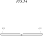
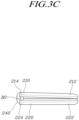
- the electronic device 200 may be folded in at least one manner among in-folding, out-folding, and in/out-folding.
- In-folding may refer to a way to fold the display 230 inward
- out-folding may refer to a way to fold the display 230 outward to allow the first housing 210 and the second housing 220 to face each other.
- In/out-folding may refer to a way to fold a portion of the display 230 inward and fold the rest outward.
- An in-folding electronic device in which the display 230 is folded inward is described below as an example.
- the first housing 210 may be rotated clockwise (or counterclockwise), and the second housing 220 may be rotated counterclockwise (or clockwise).
- the first housing 210 may be fixed while the second housing 220 is rotated clockwise (or counterclockwise), or the second housing 220 may be fixed while the first housing 210 is rotated counterclockwise (or clockwise).
- the first housing 210 and the second housing 220 may be disposed substantially parallel to each other on a plane.
- the hinge housing 240 may be fully hidden from the outside by the first housing 210 and/or the second housing 220.
- the hinge housing 240 of the electronic device 200 may be exposed to the outside in its maximum area in the fully folded state and, while changing from the fully folded state to the fully unfolded state, the area exposed to the outside may gradually reduce.
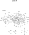
- a hinge structure unit 30 (e.g., the first hinge structure 30a or the second hinge structure 30b of FIG. 2A or FIG. 2B ) may be either the first hinge structure 30a or the second hinge structure 30b described above.
- first hinge structure 30a e.g., the first hinge structure 30a or the second hinge structure 30b of FIG. 2A or FIG. 2B
- second hinge structure 30b described above.
- the description focuses primarily on the first hinge structure 30a.
- the first rotator 310 may be disposed on an upper surface (e.g., z-axis) of the first housing.
- the first rotator 310 may extend in a left/right direction (e.g., ⁇ y-axis).
- the first rotator 310 may be connected to the first housing (e.g., the first housing 210 of FIG. 2A or FIG. 2B ) through a fixing member (not shown).
- the first rotator 310 may be coupled to the fixing bracket 330 to be rotatable about a first rotational axis 311. For example, when the electronic device (e.g., the electronic device 200 of FIG. 2A ) is folded or unfolded, the first rotator 310, together with the first housing 210, may be rotated about the first rotational axis 311.
- the second rotator 320 may be disposed on an upper surface (e.g., z-axis) of the second housing.
- the second rotator 320 may extend in a left/right direction (e.g., ⁇ y-axis).
- the second rotator 320 may be connected to the second housing (e.g., the second housing 220 of FIG. 2A or FIG. 2B ).
- the second rotator 320 may be coupled to the fixing bracket 330 to be rotatable about a second rotational axis 321. For example, when the electronic device 200 is folded or unfolded, the second rotator 320, together with the second housing 220, may be rotated about the second rotational axis 321.
- the second rotational axis 321 and the first rotational axis 311 may be spaced apart from each other and may be substantially parallel to each other.
- the second rotator 320 together with the second housing 220, may be rotated about the second rotational axis 321.
- the first rotator 310 and the second rotator 320 may have a symmetrical structure with respect to a folding axis F (e.g., the folding axis F of FIG. 2A ) of the electronic device 200.
- the fixing bracket 330 may be disposed inside the hinge housing (e.g., the hinge housing 240 of FIG. 2A or FIG. 2B ).
- the first rotator 310 and/or the second rotator 320 may be rotatably connected to the fixing bracket 330.
- the first cam 340 may be disposed in front (e.g., +x axis) of the first rotator 310.
- the first cam 340 may include a first camshaft 341.
- the first camshaft 341 may pass through one end (e.g., the x axis) of the first cam 340 and may be rotatably connected to the first cam 340.
- the first camshaft 341 may pass through the first support portion 382 and be fixed to the support portion 380 through a first fixing pin 391.
- the first cam 340 may be interlocked with the first rotator 310. For example, the first cam 340 may be rotated when the first rotator 310 rotates.
- the second cam 350 may be disposed in front (e.g., x axis) of the second rotator 320.
- the second cam 350 may include a second camshaft 351.
- the second camshaft 351 may pass through one end (e.g., the x axis) of the second cam 350 and may be rotatably connected to the second cam 350.
- the second camshaft 351 may pass through the second support portion 383 and be fixed to the support portion 380 through a second fixing pin 392.
- the second camshaft 351 may be spaced apart from and parallel to the first camshaft 341.
- the second cam 350 may be interlocked with the second rotator 320.
- the second cam 350 may be rotated when the second rotator 320 rotates.
- the first cam 340 and the second cam 350 may be symmetrical with respect to the folding axis F of the electronic device 200.
- the gear unit 360 may be disposed between the first and second rotators 310 and 320 and the first and second cams 340 and 350.
- the gear unit 360 may include a plurality of gears that interlock the first cam 340 and the second cam 350.
- the gear unit 360 may include, e.g., a plurality of shaft gears and a plurality of idle gears connected to the first and second camshafts 341 and 351.
- the gear unit 360 may transfer force to the second housing 220 so that when the first housing 210 is rotated, the second housing 220 may be rotated together.
- the gear unit 360 may transfer force to the first housing 210 so that when the second housing 220 is rotated, the first housing 210 may be rotated together.
- the elastic portion 370 may provide an elastic force to the hinge structure unit 30 to keep the electronic device 200 in the unfolded state or the folded state.
- the support portion 380 may be positioned before (e.g., x axis) of the cams 340 and 350.
- the support portion 380 may support the elastic portion 370.
- the support portion 380 may support the elastic members 371 and 372 to prevent the elastic members 371 and 372 from escaping off in the x-axis direction, for example.
- the support portion 380 may include the first support portion 382 that is formed on one side (e.g., -y axis) of the support body portion 381 to have the first camshaft 341 inserted therein and the second support portion 383 that is formed on the other side (e.g., y axis) to have the second camshaft 351 inserted therein.
- FIG. 5 is an exploded perspective view illustrating a rotator (e.g., a first rotator 310of FIG. 4 ) and a cam (e.g., a first cam 340 of FIG. 4 ) included in a hinge structure (e.g., a hinge structure unit 30 of FIG. 4 ) according to an embodiment of the disclosure.
- a rotator e.g., a first rotator 310of FIG. 4
- a cam e.g., a first cam 340 of FIG. 4
- a hinge structure e.g., a hinge structure unit 30 of FIG. 4
- the first rotator 310 may include a first rotator body 312, a first guide portion 314, or a first interlocking guide 316.
- the first guide portion 314 may be formed at one end (e.g., y axis) of the first rotator body 312.
- the first guide portion 314 may be formed to protrude from the first rotator body 312.
- the first guide portion 314 may be formed, e.g., in a semicircular shape.
- the first guide portion 314 may be rotatably connected to the fixing bracket 330 and may support the rotation of the first rotator 310.
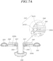
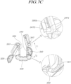
- the first guide portion 314 may be inserted into, e.g., a guide groove (not shown) formed in one surface of the fixing bracket 330 (refer to FIG. 7C ).
- the first interlocking guide 316 may include a first vertical portion 3161, a second vertical portion 3162, a first horizontal portion 3163, and a second horizontal portion 3164.
- the first vertical portion 3161 may extend upward (e.g., -z axis) from the first rotator body 312.
- the first vertical portion 3161 may include a first connection portion 3161a that is bent from one end of the first vertical portion 3161 toward the second horizontal portion 3164 and is connected to the second horizontal portion 3164.
- the second vertical portion 3162 may extend upward (e.g., -z-axis) from the first rotator body 312.
- the second vertical portion 3162 may include a second connection portion 3162a that is bent from one end of the second vertical portion 3162 toward the second horizontal portion 3164 and is connected to the second horizontal portion 3164.
- the first vertical portion 3161 and the second vertical portion 3162 may be spaced apart from each other in the left/right direction (e.g., ⁇ y-axis) with the first interlocking hole 316h interposed therebetween.
- the first horizontal portion 3163 may be positioned on one surface (e.g., an upper surface) of the first rotator body 312.
- the first horizontal portion 3163 may connect the first vertical portion 3161 and the second vertical portion 3162.
- the second horizontal portion 3164 may be positioned over (e.g., -z axis) of the first horizontal portion 3163.
- the first horizontal portion 3163 and the second horizontal portion 3164 may be spaced apart from each other in the upper/lower direction (e.g., ⁇ z-axis) with the first interlocking hole 316h interposed therebetween.
- the second horizontal portion 3164 may connect the first vertical portion 3161 and the second vertical portion 3162.
- One end (e.g., -y axis) of the second horizontal portion 3164 may be connected to, e.g., the first connection portion 3161a of the first vertical portion 3161.
- the other end (e.g., y axis) of the second horizontal portion 3164 may be connected to, e.g., the second connection portion 3162a of the second vertical portion 3162.
- the first interlocking hole 316h may extend in the left/right direction (e.g., ⁇ y-axis).
- the first interlocking hole 316h may be defined by an inner surface of the first interlocking guide 316.
- the first interlocking hole 316h may mean, e.g., a space surrounded by the first vertical portion 3161, the second vertical portion 3162, the first horizontal portion 3163, and the second horizontal portion 3164.
- the first interlocking hole 316h may form a sliding section where the first interlocking protrusion 347 of the first cam 340 moves when the first rotator 310 and the first cam 340 are interlocked.
- the first cam 340 may include a first cam body 342, a first part 344, and a second part 346.
- the first cam body 342 may connect the first part 344 and the second part 346.
- the first part 344 may be formed at one end (e.g., y axis) of the first cam body 342.
- a hole 344h into which the first camshaft 341 is inserted may be formed in the first part 344.
- the second part 346 may be formed at the other end (e.g., -y axis) of the first cam body 342.
- the second part 346 may support interlocking of the first rotator 310 and the first cam 340.
- the second part 346 may contact one side surface of the first interlocking guide 316 to support interlocking between the first rotator 310 and the first cam 340 when insertion of the first interlocking protrusion 347 into the first interlocking hole 316h is completed.
- the second part 346 may have the first interlocking protrusion 347 for interconnecting the first rotator 310 and the first cam 340.
- the first interlocking protrusion 347 may protrude from the second part 346 in a direction (e.g., -x axis) toward the first interlocking hole 316h.
- the first interlocking protrusion 347 may allow the first rotator 310 and the first cam 340 to interlock with each other, maintaining the interlocking between the first rotator 310 and the first cam 340.
- the first interlocking protrusion 347 may be inserted into the first interlocking hole 316h, preventing the first cam 340 from escaping off the first interlocking guide 316.
- the first interlocking protrusion 347 may slide in the left/right direction (e.g., ⁇ y-axis) along the first interlocking hole 316h in the first interlocking guide 316.
- the first anti-escape portion 3472 may be formed at an end of the first protrusion shaft 3471.
- the first anti-escape portion 3472 may extend in the upper/lower direction (e.g., ⁇ z-axis) from an end of the first protrusion shaft 3471.
- the vertical width (e.g., ⁇ z-axis) of the first anti-escape portion 3472 may be larger than the horizontal width (e.g., ⁇ y-axis) of the first anti-escape portion 3472.
- the first end 3472a may form a step from the upper surface (e.g., -z axis) of the first protrusion shaft 3471, preventing the first interlocking protrusion 347 from escaping off. After the first interlocking protrusion 347 is inserted into the first interlocking hole 316h, the first end 3472a may contact a side surface 3164a of the second horizontal portion 3164, preventing the first interlocking protrusion 347 from escaping off the first interlocking guide 316.
- the first rotator 310 may be moved in direction 1 (e.g., an oblique direction) so that the first interlocking protrusion 347 is slid along the first interlocking hole 316h. Thereafter, the first rotator 310 may be rotated in direction (2) (e.g., clockwise) so that the first guide portion 314 is inserted into the guide groove (not shown) formed in the fixing bracket 330.
- direction 1 e.g., an oblique direction
- direction (2) e.g., clockwise
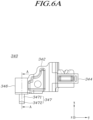
- FIG. 9A is a plan view illustrating a first cam 440 of FIG. 8 according to an embodiment of the disclosure.
- FIG. 9B is a cross-sectional view taken along line B-B of FIG. 9A according to an embodiment of the disclosure.
- FIG. 10A is a plan view illustrating a first cam of FIG. 8 according to an embodiment of the disclosure.
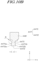
- FIG. 10B is a cross-sectional view taken along line C-C of FIG. 10A according to an embodiment of the disclosure.
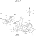
- the first interlocking guide 416 may have an escape portion 4165 that forms an escape section 4165s where a first interlocking protrusion 447 of the first cam 440 is rotated for interlocking between the first cam 440 and the first rotator 410.
- the escape section 4165s may form at least a portion of a first interlocking hole 416h.
- the first interlocking protrusion 447 may allow the first rotator 410 and the first cam 440 to interlock with each other, maintaining the interlocking between the first rotator 410 and the first cam 440.
- the first interlocking protrusion 447 may be inserted into the first interlocking hole 416h, preventing the first cam 440 from escaping off the first interlocking guide 416.
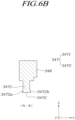
- the first interlocking protrusion 447 may be rotated within, e.g., the escape section 4165s and then moved along the sliding section. Accordingly, two opposite ends (e.g., 4472a and 4472b (refer to FIG. 10B )) of the first interlocking protrusion 447 may be seated on side surfaces (e.g., 4163a and 4164a) of the first interlocking guide 416.
- a first interlocking protrusion 447 may include a first protrusion shaft 4471 and/or a first anti-escape portion 4472.
- a reinforcement portion 4471c, 4471d, or 4471e for reinforcing strength may be formed at the start end (e.g., portion D of FIG. 10B ) of the first protrusion shaft 4471.
- the reinforcement portion 4471c, 4471d, or 4471e may be formed on at least one surface of the first protrusion shaft 4471.
- the reinforcement portion 4471c, 4471d, or 4471e may be formed on an upper surface 4471a and/or a lower surface 4471b of the first protrusion shaft 4471.
- the reinforcement portion 4471c, 4471d, or 4471e may be formed in various shapes for strength reinforcement.
- the reinforcement portion 4471c (refer to part (a) of FIG. 11 ) may be formed to have a predetermined inclination while extending from one surface (e.g., surface 446a) of the second part 446 to one surface 4471a and/or 4471b of the first protrusion shaft 4471.
- the reinforcement portion 4471d (refer to part (b) of FIG.
- a hinge structure 500 may include a first rotator 510 and/or a first cam 540.
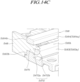
- FIGS. 14A , 14B , and 14C are views illustrating assembly of a rotator (e.g., first rotator 510 of FIG. 12 ) and a cam (e.g., a first cam 540 of FIG. 12 ) included in a hinge structure (e.g., a hinge structure 500 of FIG. 12 ) according to an embodiment of the disclosure.
- a rotator e.g., first rotator 510 of FIG. 12
- a cam e.g., a first cam 540 of FIG. 12
- a hinge structure e.g., a hinge structure 500 of FIG. 12
- the first interlocking protrusion 547 of the first cam 540 may be moved to be inserted into a first interlocking hole 516h of the first rotator 510.
- the first anti-escape portion 5472 when inserted into the first interlocking hole 516h, the first anti-escape portion 5472 may contact the inner surface of a first interlocking guide 516 and be pressurized towards the elastic space ES by the reaction force P according to the contact.
- the first end 5472a of the first anti-escape portion 5472 may contact, e.g., a second horizontal portion 5164 of the first interlocking guide 516 and be pressurized towards the elastic space ES by the reaction force P according to the contact.
- the deformed first anti-escape portion 5472 may be restored to the original shape by the reaction force according to the insertion into the first interlocking hole 516h.
- the first end 5472a of the first anti-escape portion 5472 may abut one side surface 5164s of the second horizontal portion 5164, and the second end 5472b of the first anti-escape portion 5472 may abut one side surface 5163s of the first horizontal portion 5163.
- a foldable electronic device (e.g., the foldable electronic device 200 of FIG. 2A ) may comprise the hinge structure unit 30 including the first hinge structure 30a and the second hinge structure 30b and a fixing bracket 330 to which the hinge structure unit 30 is rotatably coupled.
- the first hinge structure 30a or the second hinge structure 30b may include a rotator (e.g., first rotator 310) provided with an interlocking hole (e.g., first interlocking hole 316h) and a cam (e.g., first cam 340) having an end provided with an interlocking protrusion (e.g., first interlocking protrusion 347) to be fitted into the first interlocking hole 316h to be assembled to the first rotator 310.
- a rotator e.g., first rotator 310
- an interlocking hole e.g., first interlocking hole 316h
- a cam e.g., first cam 340 having an end provided with an interlocking protrusion (e.g., first interlocking protrusion 347) to be fitted into the first interlocking hole 316h to be assembled to the first rotator 310.
- the first interlocking protrusion 347 may include a first protrusion shaft 3471 protruding from the cam and extending in a first direction (-x axis of FIG. 5 ) which is a length direction of the first interlocking protrusion 347 and the anti-escape portion 3472 extending from an end of the first protrusion shaft 3471 in a second direction (-z axis of FIG. 5 ) perpendicular to the first direction and a third direction (z axis of FIG. 5 ) opposite to the second direction and forming a step from the first protrusion shaft 3471.
Landscapes
- Engineering & Computer Science (AREA)
- General Engineering & Computer Science (AREA)
- Computer Hardware Design (AREA)
- Theoretical Computer Science (AREA)
- Mechanical Engineering (AREA)
- Human Computer Interaction (AREA)
- Physics & Mathematics (AREA)
- General Physics & Mathematics (AREA)
- Signal Processing (AREA)
- Telephone Set Structure (AREA)
Applications Claiming Priority (3)
| Application Number | Priority Date | Filing Date | Title |
|---|---|---|---|
| KR20220038928 | 2022-03-29 | ||
| KR1020220064915A KR20230140311A (ko) | 2022-03-29 | 2022-05-26 | 힌지 구조물 및 이를 포함하는 폴더블 전자 장치 |
| PCT/KR2022/019960 WO2023191243A1 (fr) | 2022-03-29 | 2022-12-08 | Structure de charnière et appareil électronique pliable la comprenant |
Publications (2)
| Publication Number | Publication Date |
|---|---|
| EP4398068A1 true EP4398068A1 (fr) | 2024-07-10 |
| EP4398068A4 EP4398068A4 (fr) | 2025-02-26 |
Family
ID=88194124
Family Applications (1)
| Application Number | Title | Priority Date | Filing Date |
|---|---|---|---|
| EP22935915.3A Pending EP4398068A4 (fr) | 2022-03-29 | 2022-12-08 | Structure de charnière et appareil électronique pliable la comprenant |
Country Status (2)
| Country | Link |
|---|---|
| US (1) | US12259762B2 (fr) |
| EP (1) | EP4398068A4 (fr) |
Family Cites Families (25)
| Publication number | Priority date | Publication date | Assignee | Title |
|---|---|---|---|---|
| US3241724A (en) * | 1963-09-13 | 1966-03-22 | Nathan B Lerner | Means for heating the contents of a container or dispenser as same is being discharged or dispensed |
| US6687224B1 (en) * | 2000-02-28 | 2004-02-03 | Orckit Communications, Ltd. | Bandwidth sharing method |
| KR101034577B1 (ko) | 2008-04-23 | 2011-05-12 | 주식회사 다이아벨 | 슬라이드 힌지 모듈 |
| KR20110091966A (ko) | 2010-02-08 | 2011-08-17 | 주식회사 두리정밀 | 슬라이드 휴대폰의 고효율 힌지모듈 |
| KR20120026268A (ko) | 2010-09-09 | 2012-03-19 | (주) 프렉코 | 휴대 단말기용 슬라이드-틸트 힌지장치 |
| KR101888154B1 (ko) * | 2012-02-06 | 2018-08-14 | 삼성전자주식회사 | 전자기기 |
| KR101941584B1 (ko) | 2017-05-15 | 2019-01-25 | 주식회사 다이아벨 | 밴딩 힌지 장치 및 이를 구비하는 전자기기 |
| TWI679517B (zh) * | 2017-05-23 | 2019-12-11 | 仁寶電腦工業股份有限公司 | 鉸鏈結構與電子裝置 |
| KR102587589B1 (ko) | 2019-02-19 | 2023-10-12 | 삼성전자주식회사 | 힌지 구조물 및 이를 포함하는 전자 장치 |
| CN111698355B (zh) | 2019-03-15 | 2021-07-09 | 华为技术有限公司 | 一种转轴机构及移动终端 |
| KR102375556B1 (ko) * | 2019-04-30 | 2022-03-17 | 삼성전자주식회사 | 힌지 구조물 및 이를 포함하는 전자 장치 |
| KR102716697B1 (ko) * | 2019-06-03 | 2024-10-15 | 삼성전자주식회사 | 폴더블 전자 장치 및 그의 힌지 구조물 |
| CN112145542B (zh) | 2019-06-27 | 2022-01-11 | 华为技术有限公司 | 折叠模组及折叠式电子设备 |
| US11243578B2 (en) * | 2019-08-02 | 2022-02-08 | Dell Products L.P. | Gear synchronized dual axis pivot hinge |
| KR102668216B1 (ko) | 2019-12-02 | 2024-05-23 | 삼성전자주식회사 | 힌지 조립체를 포함하는 폴더블 전자 장치 |
| CN113280033B (zh) | 2020-02-20 | 2022-07-29 | 北京小米移动软件有限公司 | 铰链、铰链组件和折叠式电子设备 |
| KR102250196B1 (ko) | 2020-04-22 | 2021-05-10 | 주식회사 이음 | 폴더블 디스플레이 장치 |
| WO2021235569A1 (fr) | 2020-05-19 | 2021-11-25 | 엘지전자 주식회사 | Dispositif électronique |
| KR102937674B1 (ko) * | 2020-07-24 | 2026-03-11 | 삼성전자주식회사 | 힌지 구조물 및 이를 포함하는 전자 장치 |
| US11339759B2 (en) | 2020-10-09 | 2022-05-24 | GM Global Technology Operations LLC | Engine torque estimation and control systems and methods |
| CN116635639A (zh) * | 2020-11-18 | 2023-08-22 | 三星电子株式会社 | 包括扭矩结构的电子设备 |
| CN112911033B (zh) * | 2021-01-20 | 2023-07-18 | 惠州Tcl移动通信有限公司 | 一种旋转屏转轴结构及旋转屏 |
| EP4283433A4 (fr) * | 2021-06-29 | 2024-10-02 | Samsung Electronics Co., Ltd. | Ensemble charnière et dispositif électronique le comprenant |
| EP4318181B1 (fr) * | 2021-07-20 | 2025-09-17 | Samsung Electronics Co., Ltd. | Dispositif électronique comprenant un module charnière |
| EP4344173B1 (fr) * | 2021-08-09 | 2026-02-25 | Samsung Electronics Co., Ltd. | Structure de charnière et appareil électronique pliable la comprenant |
-
2022
- 2022-12-08 EP EP22935915.3A patent/EP4398068A4/fr active Pending
- 2022-12-16 US US18/082,943 patent/US12259762B2/en active Active
Also Published As
| Publication number | Publication date |
|---|---|
| US20230315162A1 (en) | 2023-10-05 |
| US12259762B2 (en) | 2025-03-25 |
| EP4398068A4 (fr) | 2025-02-26 |
Similar Documents
| Publication | Publication Date | Title |
|---|---|---|
| US11886257B2 (en) | Hinge structure and electronic device including the same | |
| US12066872B2 (en) | Hinge assembly and electronic device including the same | |
| US12107979B2 (en) | Electronic device capable of folding motion and sliding motion | |
| EP4332721A1 (fr) | Ensemble charnière et dispositif électronique le comprenant | |
| US12461570B2 (en) | Electronic device comprising hinge assembly | |
| US12366895B2 (en) | Hinge assembly and electronic device including the same | |
| US12045535B2 (en) | Expandable display control method and electronic device supporting same | |
| US20220408580A1 (en) | Hinge assembly and foldable electronic device including the same | |
| US12507360B2 (en) | Electronic device with hinge assembly | |
| EP4318183B1 (fr) | Dispositif électronique comprenant une structure charnière pour un affichage pliable | |
| US12498766B2 (en) | Hinge assembly and electronic device including the same | |
| US20230400881A1 (en) | Hinge assembly and electronic device including the same | |
| US11889007B2 (en) | Hinge structure and electronic device including the same | |
| US12436571B2 (en) | Electronic device including reinforcing structure | |
| US12167548B2 (en) | Foldable electronic device | |
| US11971756B2 (en) | Electronic device including flexible display | |
| US20250142749A1 (en) | Electronic device comprising hinge-linked foot structure | |
| US12181934B2 (en) | Electronic device comprising hinge assembly | |
| EP4398068A1 (fr) | Structure de charnière et appareil électronique pliable la comprenant | |
| EP4336651A1 (fr) | Dispositif électronique comprenant une antenne | |
| US20260075129A1 (en) | Foldable electronic device including structure for reducing damage of hinge | |
| EP4733889A1 (fr) | Dispositif électronique pliable comprenant des rotateurs | |
| US20250234466A1 (en) | Electronic device comprising structure for supporting display | |
| US20250148582A1 (en) | Electronic device and method for visual distortion correction | |
| CN118176469A (zh) | 铰链结构和包括该铰链结构的可折叠电子装置 |
Legal Events
| Date | Code | Title | Description |
|---|---|---|---|
| STAA | Information on the status of an ep patent application or granted ep patent |
Free format text: STATUS: THE INTERNATIONAL PUBLICATION HAS BEEN MADE |
|
| PUAI | Public reference made under article 153(3) epc to a published international application that has entered the european phase |
Free format text: ORIGINAL CODE: 0009012 |
|
| STAA | Information on the status of an ep patent application or granted ep patent |
Free format text: STATUS: REQUEST FOR EXAMINATION WAS MADE |
|
| 17P | Request for examination filed |
Effective date: 20240405 |
|
| AK | Designated contracting states |
Kind code of ref document: A1 Designated state(s): AL AT BE BG CH CY CZ DE DK EE ES FI FR GB GR HR HU IE IS IT LI LT LU LV MC ME MK MT NL NO PL PT RO RS SE SI SK SM TR |
|
| A4 | Supplementary search report drawn up and despatched |
Effective date: 20250129 |
|
| RIC1 | Information provided on ipc code assigned before grant |
Ipc: F16C 11/04 20060101ALI20250123BHEP Ipc: H04M 1/02 20060101ALI20250123BHEP Ipc: G06F 1/16 20060101AFI20250123BHEP |
|
| DAV | Request for validation of the european patent (deleted) | ||
| DAX | Request for extension of the european patent (deleted) |