EP4398395A1 - Bloc-batterie et dispositif le comprenant - Google Patents
Bloc-batterie et dispositif le comprenant Download PDFInfo
- Publication number
- EP4398395A1 EP4398395A1 EP23843262.9A EP23843262A EP4398395A1 EP 4398395 A1 EP4398395 A1 EP 4398395A1 EP 23843262 A EP23843262 A EP 23843262A EP 4398395 A1 EP4398395 A1 EP 4398395A1
- Authority
- EP
- European Patent Office
- Prior art keywords
- cell
- cover
- battery
- support plate
- fastening hole
- Prior art date
- Legal status (The legal status is an assumption and is not a legal conclusion. Google has not performed a legal analysis and makes no representation as to the accuracy of the status listed.)
- Pending
Links
Images




Classifications
-
- H—ELECTRICITY
- H01—ELECTRIC ELEMENTS
- H01M—PROCESSES OR MEANS, e.g. BATTERIES, FOR THE DIRECT CONVERSION OF CHEMICAL ENERGY INTO ELECTRICAL ENERGY
- H01M50/00—Constructional details or processes of manufacture of the non-active parts of electrochemical cells other than fuel cells, e.g. hybrid cells
- H01M50/20—Mountings; Secondary casings or frames; Racks, modules or packs; Suspension devices; Shock absorbers; Transport or carrying devices; Holders
- H01M50/262—Mountings; Secondary casings or frames; Racks, modules or packs; Suspension devices; Shock absorbers; Transport or carrying devices; Holders with fastening means, e.g. locks
- H01M50/264—Mountings; Secondary casings or frames; Racks, modules or packs; Suspension devices; Shock absorbers; Transport or carrying devices; Holders with fastening means, e.g. locks for cells or batteries, e.g. straps, tie rods or peripheral frames
-
- H—ELECTRICITY
- H01—ELECTRIC ELEMENTS
- H01M—PROCESSES OR MEANS, e.g. BATTERIES, FOR THE DIRECT CONVERSION OF CHEMICAL ENERGY INTO ELECTRICAL ENERGY
- H01M4/00—Electrodes
- H01M4/02—Electrodes composed of, or comprising, active material
- H01M4/24—Electrodes for alkaline accumulators
- H01M4/242—Hydrogen storage electrodes
-
- H—ELECTRICITY
- H01—ELECTRIC ELEMENTS
- H01M—PROCESSES OR MEANS, e.g. BATTERIES, FOR THE DIRECT CONVERSION OF CHEMICAL ENERGY INTO ELECTRICAL ENERGY
- H01M50/00—Constructional details or processes of manufacture of the non-active parts of electrochemical cells other than fuel cells, e.g. hybrid cells
- H01M50/20—Mountings; Secondary casings or frames; Racks, modules or packs; Suspension devices; Shock absorbers; Transport or carrying devices; Holders
- H01M50/204—Racks, modules or packs for multiple batteries or multiple cells
- H01M50/207—Racks, modules or packs for multiple batteries or multiple cells characterised by their shape
- H01M50/211—Racks, modules or packs for multiple batteries or multiple cells characterised by their shape adapted for pouch cells
-
- H—ELECTRICITY
- H01—ELECTRIC ELEMENTS
- H01M—PROCESSES OR MEANS, e.g. BATTERIES, FOR THE DIRECT CONVERSION OF CHEMICAL ENERGY INTO ELECTRICAL ENERGY
- H01M50/00—Constructional details or processes of manufacture of the non-active parts of electrochemical cells other than fuel cells, e.g. hybrid cells
- H01M50/20—Mountings; Secondary casings or frames; Racks, modules or packs; Suspension devices; Shock absorbers; Transport or carrying devices; Holders
- H01M50/249—Mountings; Secondary casings or frames; Racks, modules or packs; Suspension devices; Shock absorbers; Transport or carrying devices; Holders specially adapted for aircraft or vehicles, e.g. cars or trains
-
- H—ELECTRICITY
- H01—ELECTRIC ELEMENTS
- H01M—PROCESSES OR MEANS, e.g. BATTERIES, FOR THE DIRECT CONVERSION OF CHEMICAL ENERGY INTO ELECTRICAL ENERGY
- H01M50/00—Constructional details or processes of manufacture of the non-active parts of electrochemical cells other than fuel cells, e.g. hybrid cells
- H01M50/20—Mountings; Secondary casings or frames; Racks, modules or packs; Suspension devices; Shock absorbers; Transport or carrying devices; Holders
- H01M50/256—Carrying devices, e.g. belts
-
- H—ELECTRICITY
- H01—ELECTRIC ELEMENTS
- H01M—PROCESSES OR MEANS, e.g. BATTERIES, FOR THE DIRECT CONVERSION OF CHEMICAL ENERGY INTO ELECTRICAL ENERGY
- H01M50/00—Constructional details or processes of manufacture of the non-active parts of electrochemical cells other than fuel cells, e.g. hybrid cells
- H01M50/20—Mountings; Secondary casings or frames; Racks, modules or packs; Suspension devices; Shock absorbers; Transport or carrying devices; Holders
- H01M50/262—Mountings; Secondary casings or frames; Racks, modules or packs; Suspension devices; Shock absorbers; Transport or carrying devices; Holders with fastening means, e.g. locks
-
- H—ELECTRICITY
- H01—ELECTRIC ELEMENTS
- H01M—PROCESSES OR MEANS, e.g. BATTERIES, FOR THE DIRECT CONVERSION OF CHEMICAL ENERGY INTO ELECTRICAL ENERGY
- H01M50/00—Constructional details or processes of manufacture of the non-active parts of electrochemical cells other than fuel cells, e.g. hybrid cells
- H01M50/20—Mountings; Secondary casings or frames; Racks, modules or packs; Suspension devices; Shock absorbers; Transport or carrying devices; Holders
- H01M50/271—Lids or covers for the racks or secondary casings
- H01M50/273—Lids or covers for the racks or secondary casings characterised by the material
- H01M50/276—Inorganic material
-
- H—ELECTRICITY
- H01—ELECTRIC ELEMENTS
- H01M—PROCESSES OR MEANS, e.g. BATTERIES, FOR THE DIRECT CONVERSION OF CHEMICAL ENERGY INTO ELECTRICAL ENERGY
- H01M50/00—Constructional details or processes of manufacture of the non-active parts of electrochemical cells other than fuel cells, e.g. hybrid cells
- H01M50/50—Current conducting connections for cells or batteries
- H01M50/502—Interconnectors for connecting terminals of adjacent batteries; Interconnectors for connecting cells outside a battery casing
- H01M50/503—Interconnectors for connecting terminals of adjacent batteries; Interconnectors for connecting cells outside a battery casing characterised by the shape of the interconnectors
-
- H—ELECTRICITY
- H01—ELECTRIC ELEMENTS
- H01M—PROCESSES OR MEANS, e.g. BATTERIES, FOR THE DIRECT CONVERSION OF CHEMICAL ENERGY INTO ELECTRICAL ENERGY
- H01M50/00—Constructional details or processes of manufacture of the non-active parts of electrochemical cells other than fuel cells, e.g. hybrid cells
- H01M50/50—Current conducting connections for cells or batteries
- H01M50/502—Interconnectors for connecting terminals of adjacent batteries; Interconnectors for connecting cells outside a battery casing
- H01M50/505—Interconnectors for connecting terminals of adjacent batteries; Interconnectors for connecting cells outside a battery casing comprising a single busbar
-
- H—ELECTRICITY
- H01—ELECTRIC ELEMENTS
- H01M—PROCESSES OR MEANS, e.g. BATTERIES, FOR THE DIRECT CONVERSION OF CHEMICAL ENERGY INTO ELECTRICAL ENERGY
- H01M2220/00—Batteries for particular applications
- H01M2220/20—Batteries in motive systems, e.g. vehicle, ship, plane
-
- Y—GENERAL TAGGING OF NEW TECHNOLOGICAL DEVELOPMENTS; GENERAL TAGGING OF CROSS-SECTIONAL TECHNOLOGIES SPANNING OVER SEVERAL SECTIONS OF THE IPC; TECHNICAL SUBJECTS COVERED BY FORMER USPC CROSS-REFERENCE ART COLLECTIONS [XRACs] AND DIGESTS
- Y02—TECHNOLOGIES OR APPLICATIONS FOR MITIGATION OR ADAPTATION AGAINST CLIMATE CHANGE
- Y02E—REDUCTION OF GREENHOUSE GAS [GHG] EMISSIONS, RELATED TO ENERGY GENERATION, TRANSMISSION OR DISTRIBUTION
- Y02E60/00—Enabling technologies; Technologies with a potential or indirect contribution to GHG emissions mitigation
- Y02E60/10—Energy storage using batteries
Definitions
- the present invention relates to a battery pack and a device including the same, and more particularly, a battery pack manufactured by a cell-to-pack technology, and a device including the same.
- an object of the present invention is to provide a battery pack, a device, and the like, which reduce the overall weight and volume of the battery pack and improve the energy density of the battery pack.
- Another object of the present invention is to provide a battery pack which facilitates handling and mounting of battery cells in the manufacturing process of a battery pack including a plurality of battery cells, accomplishes simplification and weight reduction of the structure required for mounting battery cells while preventing damage to the battery cells, thereby reducing manufacturing costs and strengthening the fixing force of the battery cells, and a device including the same.
- a battery pack comprising: a battery assembly including a plurality of cell units arranged side by side in one direction, and a pack case that houses the battery assembly in an inner space, wherein the cell unit includes at least one battery cell and a cell cover covering a part of the battery cell, and wherein the battery assembly penetrates through the cell cover to thereby restrict a relative movement of the plurality of cell units.
- the cell cover is formed with a cell cover fastening hole, and the fixing unit may penetrate through the cell cover fastening hole to thereby fix the plurality of cell units.
- the battery cells are vertically arranged so that one edge corresponds to the bottom surface of the pack case, the cell cover covers an upper side edge of the vertically arranged battery cell, and the lower side edge of the battery cell may be opened.
- the cell cover includes a second surface and a third surface arranged in parallel to one surface of the battery cell, and a first surface extending between the second surface and the third surface, and a cross section of the cell cover may have an n-shape.
- the second surface and the third surface may be formed with a cell unit coupling hole into which the fixing unit is inserted.
- the cell unit further includes a busbar frame coupled to an end part in the longitudinal direction of the cell cover, and an electrode lead of the battery cell housed in the cell cover may be electrically connected to a busbar mounted on the busbar frame.
- One surface of the busbar frame is formed with a busbar frame groove, and the shape of the busbar frame groove may correspond to the shape of the outer peripheral surface of the fixing unit.
- the battery assembly includes a support plate in contact with one surface of an outermost cell unit among the plurality of cell units, and the fixing unit may penetrate through the support plate to thereby restrict a relative movement between the plurality of cell units and the support plate.
- the support plate is formed with a plate fastening hole
- the cell cover is formed with a cell cover fastening hole
- the fixing unit may penetrate through the plate fastening hole and the cell cover fastening hole to thereby couple the plurality of cell units and the support plate.
- the battery assembly further includes an end cover located at an end part in a longitudinal direction of the plurality of cell units, and the end cover may be coupled to the support plate.
- the end cover includes a body part covering end parts in the longitudinal direction of the plurality of cell units, and a cover extension part extending from one edge of the body part toward the support plate, and the cover extension part may correspond to an end part in the longitudinal direction of the support plate.
- the fixing unit may penetrate through the cover extension part to thereby couple the end cover and the support plate.
- the cell cover is formed with a cell cover fastening hole
- the support plate is formed with a plate fastening hole
- the cover extension part is formed with a cover fastening hole
- the fixing unit may penetrate through the cell cover fastening hole, the plate fastening hole, and the cover fastening hole to thereby couple the plurality of cell units, the support plate, and the end cover.
- the battery assembly further includes a second fixing unit, and the cover extension part and an end part of the support plate may be fixed by the second fixing unit.
- the support plate is formed with a second plate fastening hole
- the cover extension part is formed with a cover fastening hole
- the second fixing unit may penetrate through the second plate fastening hole and the cover fastening hole to thereby couple the end cover and the support plate.
- the support plate is formed with a cover coupling part at a position corresponding to the cover extension part, and an outer surface of the cover coupling part and an inner surface of the cover extension part may be arranged to contact each other.
- the outer surface of the cover coupling part has a shape recessed toward the inner surface, and an inner surface of the cover extension part may be disposed on an outer surface of the recessed cover coupling part.
- the end cover may include a cover support part extending from one edge of the body part toward a lower surface of the cell unit.
- the cell cover may be formed by bending one plate material.
- a device comprising the above-mentioned battery pack.
- a cell cover having a simplified structure, and can be directly mounted on the pack case. This not only reduces the overall weight and volume of the battery pack and improves the energy density of the battery pack, but also prevents damage to the battery cells occurring in the process of directly mounting a large number of battery cells and using them, and facilitates swelling control of the battery cells and design of the gas venting path.
- the present invention can have additional other effects, which will be described in each of embodiments, or descriptions of the effects that can be easily inferred by those skilled in the art will be omitted.
- planar it means when a target portion is viewed from the upper side
- cross-sectional it means when a target portion is viewed from the side of a cross section cut vertically.
- the pack case 1100 has a space for seating each battery assembly 100, and each battery assembly 100 may be housed in a seating space of the pack case 1100.
- the battery assembly 100 may be arranged in two rows inside the pack case 1100, and the first beam 1210 may be arranged across the central part of the pack case 1100 to separate the battery assemblies 100 arranged in two rows.
- the second beam 1220 may be arranged perpendicular to the first beam 1210 to separate the battery assemblies 100 arranged in each row, and may be arranged in plural numbers at regular intervals.
- this is an example of the internal structure of the battery pack 1000, and the structure of the battery pack 1000 according to the present embodiment should not be limited to the examples mentioned above.
- the battery assembly 100 of the present embodiment may have a module-less structure.
- the module-less structure may refer to a cell-to-pack structure in which a cell structure is directly coupled to a pack structure without a module case.
- conventional battery packs 1000 have a double assembly structure in which a plurality of battery cells and several components connected thereto are assembled to form a battery module, and the plurality of battery modules are housed in the battery pack 1000 again.
- the battery module comprises a module frame or the like that forms its outer surface
- conventional battery cells are doubly protected by the module frame of the battery module and the pack case 1100 of the battery pack 1000.
- such a double assembly structure not only increases the manufacturing unit cost and the manufacturing process of the battery pack 1000, but also has a disadvantage that reassembly performance is deteriorated when defects occur in some battery cells.
- the cooling member or the like exists outside the battery module, there is a problem that a heat transfer path between the battery cell and the cooling member becomes slightly complicated.
- FIG. 2 is a view showing a battery assembly according to an embodiment of the present invention.
- FIG. 3 is an exploded perspective view of the battery assembly according to FIG. 2 .
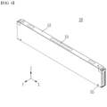
- FIG. 4 is a diagram showing a cell unit according to an embodiment of the present invention.
- FIG. 5 is an exploded perspective view of the cell unit according to FIG. 4 .
- the battery assembly 100 of the present embodiment may comprise a plurality of cell units 110, a support plate 120 that supports one surface of the cell unit 110 located on the outermost side among the plurality of cell units 110, an end cover 130 that covers a front surface and a rear surface of the plurality of cell units 110, and a fixed unit 140 that mutually couples the plurality of cell units 110.
- the battery assembly 100 of this embodiment may further comprise a handle unit 150.
- the cell unit 110 may be a minimum unit body that protects the battery cell 111 (see FIG. 4 ).
- the cell unit 110 may include at least one battery cell 111 and a cell cover 113 (see FIG. 4 ) covering a part of the battery cell 111.
- the present embodiment instead of mounting a plurality of battery cells 111 in a separate module case and mounting them on the pack case 1100 of the battery pack 1000, they can be directly mounted on the pack case 1100 while being partially covered by a cell cover 113 having a simplified structure.
- the overall weight and volume of the battery pack 1000 can be reduced, and the energy density of the battery pack 1000 can be improved.
- the two surfaces facing each other in the longitudinal direction (X-axis direction) of the cell unit 110 are referred to as a front surface and a rear surface
- two surfaces facing each other in the thickness direction (Y-axis direction) of the cell unit 110 are referred to as side surfaces
- two surfaces facing each other in the widthwise direction (Z-axis direction) of the cell unit 110 may be referred to as an upper surface and a lower surface.
- cell unit 110 The details regarding the cell unit 110 will be described in detail below with reference to FIGS. 4 and 5 .
- the support part 122 corresponds to the majority of the area of the support plate 120, and may have a plate-like shape so as to support the cell unit 110.
- the support part 122 may have a shape similar to the side surface shape of the cell unit 110.
- the plate-shaped support part 122 may include both side edges in the longitudinal direction (X-axis direction) and in the widthwise direction (Z-axis direction).
- the handle unit 150 can stably seat the battery assembly 100 inside the pack case 1100, and may include a handle that can be gripped by a user.
- One end part of the handle unit 150 may be detachably coupled to the support plate 120, and the handle unit can be removed from the support plate 120 after the mounting of the battery assembly 100 is completed.
- the body part 132 can cover a front surface or a rear surface of the plurality of cell units 110.
- the body part 132 may be located at an end part in the longitudinal direction of the plurality of cell units 110.
- the body part 132 may cover the end parts in the longitudinal direction of the plurality of cell units 110.
- the body part 132 may cover terminal portions of the battery cells included in the plurality of cell units 110.
- the body part 132 may also be referred to as a 'terminal cover part'.
- the end cover 130 may be located at the end part in the longitudinal direction (X-axis direction) of the support plate 120.
- the end cover 130 may be arranged such that the end part in the longitudinal direction (Y-axis direction) corresponds to the end part in the longitudinal direction (X-axis direction) of the support plate 120.
- the cover extension part 134 may correspond to an end part in the longitudinal direction (X-axis direction) of the support plate 120.
- the cover extension part 134 may overlap an end part in the longitudinal direction (X-axis direction) of the support plate 120.
- the cover extension part 134 may be located outside the end part in the longitudinal direction (X-axis direction) of the support plate 120.
- the cover extension part 134 may be coupled to an end part in the longitudinal direction (X-axis direction) of the support plate 120.
- the first cover extension part 134a and the second cover extension part 134b may respectively correspond to end parts of the first support plate 120a and the second support plate 120b.
- the first cover extension part 134a and the second cover extension part 134b can be respectively overlapped and coupled with end parts of the first support plate 120a and the second support plate 120b.
- the first cover extension part 134a may be located outside the first support plate 120a
- the second cover extension part 134b may be located outside the second support plate 120b.
- the outer side of a specific member may be described on the basis of the center of the battery assembly 100.
- the first cover extension part 134a and the second cover extension part 134b can respectively correspond to the cover coupling parts 124 formed on the first support plate 120a and the second support plate 120b.
- the cover extension part 134 may correspond to the cover coupling part 124 of the support plate 120.
- the cover extension part 134 may overlap with the cover coupling part 124.
- the cover extension part 134 may be coupled to the cover coupling part 124 of the support plate 120. More specifically, the cover extension part 134 may be located outside the cover coupling part 124, and an inner side surface of the cover extension part 134 may contact an outer side surface of the cover coupling part 124.
- a module frame that covers the upper, lower, left and right surfaces of the stacked battery cells and end plates that cover the front and rear surfaces thereof are provided. Also, on the outside of the battery cells, the module frame and the end plate are mainly coupled by welding. However, in this embodiment, by omitting the module frame, the end cover 130 and the support plate 120 are coupled, and the end cover 130 and the support plate 120 are coupled by a fastening member, so that a welding process may not be added. Thereby, the manufacturing process can be completed more easily and quickly. Further, a cover extension part 134 is formed on the end cover 130, and the cover coupling part 124 corresponding thereto is formed on the support plate 120, so that the coupling between the end cover 130 and the support plate 120 can be stably and easily performed.
- the cover extension part 134 may be formed with a cover fastening hole 135 for coupling with the support plate 120.
- the cover fastening hole 135 may correspond to the second plate fastening hole 125 formed in the cover coupling part 124.
- the end cover 130 may be arranged to be positioned on the same axis of the cover fastening hole 135 and the second plate fastening hole 125, and the second fixing unit 142 may be inserted into the cover fastening hole 135 and the second plate fastening hole 125, thereby being able to couple the end cover 130 and the support plate 120.
- the second fixing unit 142 may be a fastening member such as a bolt or a rivet.
- the cell units 110 of the present embodiment may be coupled by the fixing unit 140, and the relative movement of the cell unit 110 may be restricted by the fixing unit 140.
- the fixing unit 140 may couple the support plate 120 and the cell unit 110.
- the fixing unit 140 may pass through the plate fastening hole 123 formed in the first support plate 120a, then pass through the cell unit fastening hole 115 formed in the cell cover 113 included in the plurality of cell units 110, and pass through the plate fastening hole 123 formed in the second support plate 120b. Thereby, relative movement between the support plate 120 and the cell unit 110 is restricted, and the battery assembly 100 can be blocked.
- the plurality of cell units 110 can be blocked by the fixing unit 140 and the relative positions of the cell units 110 can be fixed, thereby making the handling of the battery assembly 100 easier. That is, the mounting of the battery cell 111 may be facilitated by the fixing unit 140, and a structure required for mounting the battery cell 111 is simplified, thereby capable of achieving effects such as weight reduction and manufacturing cost reduction.
- the figures show that the fixing unit 140 penetrates through the lower side portion of the battery assembly 100, but this is not necessarily the case. It is also possible to provide at other positions as long as the battery cell 111 and the electrode lead 112 are not damaged.
- the fixing unit 140 may be provided so as to penetrate through an upper side portion of the battery assembly 100, whereby the positions of the plate fastening hole 123 and the cell unit fastening hole 115 through which the fixing unit 140 penetrates can be adjusted.
- the cell unit 110 of this embodiment may include a battery cell 111 housed in a state in which the electrode assembly is impregnated with an electrolyte, a cell cover 113 that covers at least a part of the battery cell 111, a busbar frame 116 for guiding the connection between the battery cell 111 and the conductive member, and an insulating cover 118 for protecting the battery cell 111 and the conductive members connected thereto.
- the battery cell 111 of the present embodiment is a basic unit for charging and discharging, and can be provided in a pouch type that can maximize the number of stacked cells per unit area.
- the battery cell 111 provided in a pouch type can be manufactured by housing an electrode assembly including a cathode, an anode and a separator in a cell case, injecting an electrolyte material therein, and then heat-sealing a sealing part of the cell case.
- the battery cell 111 does not necessarily have to be provided in a pouch type, and can be provided in a prismatic, cylindrical or any other various shapes under the level at which a storage capacity required by a device to be mounted in the future is achieved.
- the battery cell 111 may include a housing part for housing the electrode assembly, and a sealing part formed at the edge of the battery cell 111 to seal the electrode assembly.
- the battery cell can be manufactured by housing the electrode assembly in the cell case and then sealing the edge of the cell case located outside the electrode assembly.
- the sealing part may be formed on three of the four edges of the cell case, wherein the remaining one edge may be referred to as an unsealed part.
- the battery cell 111 may comprise an electrode lead 112 for electrically connecting with a conductive member.
- the electrode lead 112 may be located to protrude in one direction from one edge of the cell case.
- One end of the electrode lead 112 is located inside the battery cell 111 to be electrically connected to a cathode or an anode of the electrode assembly, and the other end of the electrode lead 112 may be exposed to the outside of the battery cell 111 to be electrically connected to a separate member, for example, a busbar.
- the electrode lead 112 may be formed in two, and the two electrode leads 112 may be respectively located at both ends in the longitudinal direction (X-axis direction) of the battery cell 111.
- One of the two electrode leads 112 may be a cathode lead, and the other may be an anode lead.
- the battery cell 111 housed in the cell cover 113 may be formed in plural numbers.
- the plurality of battery cells 111 can be stacked in one direction to form a cell stack.
- the side surface of the cell stack may refer to one surface of the outermost battery cell 111 among the plurality of battery cells 111.
- the upper surface and the lower surface of the cell stack may be surfaces on which edges of the battery cells 111 are arranged side by side, and the front surface and the rear surface of the cell stack may be surfaces where the electrode leads 112 of the battery cells 111 are located.
- Each surface of the cell stack may correspond to each surface of the cell unit 110.
- the cell cover 113 can serve to cover at least a part of an outer surface of the battery cell 111.
- the cell cover 113 covers a part of the battery cell 111, and the other part is exposed toward the pack case 1100, thereby capable of improving cooling efficiency of the battery pack 1000 and guiding the gas generated from the battery cells 111 in a predetermined direction.
- the cell cover 113 may cover two surfaces facing each other and one surface sharing a corner with the two surfaces of the cell stack.
- the cell cover 113 may cover two side surfaces and an upper surface of the cell stack.
- the cell cover 113 may cover a side surface of the battery cell 111 arranged on the outermost side and one edge of the battery cells 111.
- the cell cover 113 has a second surface 113b and a third surface 113c, which are located in parallel to each other and spaced apart from each other, and a first surface 113a extending between the second surface 113b and the third surface 113c.
- the second surface 113b and the third surface 113c may correspond to the side surfaces of the cell unit 110.
- the first surface 113a may correspond to the upper surface of the cell unit 110.
- first surface 113a may be connected to one edge of the second surface 113b, and the other edge of the first surface 113a may be connected to one edge of the third surface 113c.
- the second surface 113b may be described as extending in the first direction from one edge of the first surface 113a
- the third surface 113c may be described as extending in the first direction from the other edge of the first surface 113a.
- the first direction is a direction substantially perpendicular to the first surface 113a, which is indicated as a -Z axis direction in the drawing.
- the cross section of the cell cover 113 may be n-shaped, wherein the cross section may refer to a cross section in the longitudinal direction (X-axis direction) of the cell cover 113.
- the second surface 113b and the third surface 113c of the cell cover 113 may be formed flat.
- the first surface 113a of the cell cover 113 may be formed flat.
- the n-shaped cell cover 113 may be formed by bending one plate material in the same direction. A method such as a press or roll forming may be applied to this bending process.
- the cell cover 113 does not necessarily have to be provided integrally, and the cell cover 113 can also be formed by connecting a plurality of plate materials.
- the cell cover 113 may cover one surface of the battery cell 111.
- a plurality of battery cells 111 may be housed in the cell cover 113 as in the present embodiment, and the second surface 113b and the third surface 113c may cover one surface of the outermost battery cell 111 among the plurality of battery cells 111.
- the cell cover 113 may cover one edge of the battery cell 111.
- the first surface 113a of the cell cover 113 may cover at least a part of one edge of the battery cell 111.
- the cell cover 113 may cover an upper side edge of the battery cell 111 vertically arranged such that one edge corresponds to the bottom surface 1110 of the pack case 1100.
- the first surface 113a of the cell cover 113 may correspond to the upper side edge of the battery cell 111 in an upright state.
- One edge of the battery cell 111 corresponding to the bottom surface 1110 of the pack case 1100 may be a portion where an unsealed part is formed.
- the cell cover 113 may separate the battery cell 111 housed therein from adjacent battery cells 111, so that the gas generated in the battery cell 111 can be interrupted from moving to the adjacent battery cell 111. Further, since the cell cover 113 is in contact with or disposed close to one surface of the battery cell 111, the heat generated in the battery cell 111 can be transferred to the cell cover 113, thereby promoting heat dissipation of the battery cell 111. Moreover, when the lower side edge of the cell cover 113 is arranged to contact the pack case 1100, a heat transfer path moving to the battery cell 111, the cell cover 113, and the pack case 1100 can be formed, the overall cooling efficiency of the battery pack 1000 may be improved.
- the lower side edge of the cell cover 113 may refer to edges located on the -Z axis on the second surface 113b and the third surface 113c.
- the cell cover 113 may not cover the lower side edge corresponding to the bottom surface 1110 of the pack case 1100 in the vertically arranged battery cells 111, and the lower side edge of the battery cell 111 can be exposed toward the bottom surface 1110. Thereby, the battery cell 111 is in contact with or located close to the bottom surface 1110 of the pack case 1100, so that heat generated from the battery cells 111 can be quickly discharged to the bottom surface 1110 of the pack case 1100. At this time, when the cooling member is located on the bottom surface 1110 of the pack case 1100, the heat dissipation effect can be further improved.
- an adhesive may be provided between the battery cell 111 and the pack case 1100 so that the battery cell 111 can be stably located in the pack case 1100. More specifically, an adhesive may be interposed between one edge of the battery cell 111 and the bottom surface 1110 of the pack case 1100. At this time, one edge of the battery cell 111 provided with the adhesive may be an unsealed part.
- the adhesive include a thermally conductive resin, TIM, and the like, and any known material can be applied as long as it is a material having thermal conductivity or adhesiveness.
- such an adhesive may be provided between the cell cover 113 and the pack case 1100 or between the battery cells 111 and the cell cover 113 to strengthen the structure of the battery pack 1000.
- each battery cell 111 is provided with a cell cover 113, so that a module case for protecting the modularized battery cells 111 can be omitted, and the battery cell 111 can be directly seated and housed inside the pack case 1100 without a module case.
- the cell case is made of a soft material, and thus, tends to be vulnerable to external impact and have low hardness. Therefore, it may not be easy to house the battery cell by itself in the inside of the pack case 1100 without housing it in the module case.
- the cell cover 113 supplements the stiffness of the battery cell 111, the battery cells 111 can be directly housed inside the pack case 1100, and can be maintained in a stacked state. Further, since the cell cover 113 makes it possible to omit conventional module cases, stacking frames, and fastening members such as bolts, the manufacturing process can be simplified, the internal structure can be simplified, and energy density can be improved accordingly.
- the stiffness of the battery cell 111 is supplemented by the cell cover 113 in this way, so that the handling of the battery cell 111 can also be facilitated in the process of assembling the battery pack 1000. More specifically, by gripping the cell cover 113 coupled with the battery cell 111 in the process of housing the battery cell 111 in the pack case 1100, the assembling process can be performed more easily.
- the cell cover 113 can be made of a material having a high melting point so that it does not melt even during thermal runaway inside the battery pack 1000. Further, the cell cover 113 can be made of a material having a mechanical strength greater than a predetermined range so as to stably support the battery cell 111, so that the battery cell 111 can be protected from external impacts and the like. Examples of the materials used for the cell cover 113 include steel, stainless steel (SUS), and the like.
- the cell cover 113 not only delays a thermal runaway phenomenon but also supplement the stiffness of the battery cell 111, thereby allowing the battery cell 111 to maintain in an upright state.
- the cell cover 113 can cover at least a part of the battery cell 111, thereby supporting the battery cell 111 and stably maintaining the stacked state of the battery cells 111 arranged upright in one direction. More specifically, the second surface 113b and the third surface 113c of the cell cover 113 can support the side surfaces of the cell stack, thereby maintaining the upright state of the battery cell 111. Further, the lower edge of the cell cover 113 can be seated on the bottom surface 1110 of the pack case 1100, thereby allowing the cell cover 113 to stand on its own and maintaining the upright state of the battery cells 111 inside the cell cover 113.
- the cell cover 113 may be coupled to cover the battery cell 111 at an upper side of the battery cell 111.
- a thermally conductive resin having adhesive properties may be provided between the cell cover 113 and the battery cell 111, but this is not necessarily the case.
- the other material may not be interposed between the cell cover 113 and the battery cell 111. This can sever to minimize the volume of the cell cover 113 to maximize the number of battery cells 111 housed inside the pack case 1100 and the battery cell 111, thereby maximizing the energy density of the battery pack 1000.
- the cell cover 113 is illustrated as covering three battery cells 111, but this is not necessarily the case, and the cell cover 113 can be designed to cover 4 or more, or 2 or less battery cells 111 according to the designer's intention.
- the cell covers 113 are described as being provided for all battery cells 111, but this is not necessarily the case, and the cell cover 113 can also be provided only on some of the plurality of battery cells 111.
- the cell cover 113 of the present embodiment is described as having an n-shape, but it can be configured in other shapes as long as it can achieve the purpose of preventing gas or the like from transferring to the electrode leads 112 and other electrical members.
- the cell cover may be formed in a ' o' shape, a 'U' shape, an 'O' shape, an 'L' shape, and the like.
- the cell cover 113 of the present embodiment may be provided with a clamping member.
- the clamping member can clamp between the different end parts of the cell covers 113 to prevent them from being space apart or deformed.
- the clamping member can be provided at the lower end of the cell cover 113 where the lower side edge of the battery cell 111 is located, and prevent the second surface 113b and the third surface 113c from being spaced apart, thereby being able to maintain the housing state of the battery cell 111.
- the clamping member may be a tape.
- the clamping member may be a metal material having elasticity.
- the cell cover 113 may be formed with a venting hole 114.
- the venting hole 114 can serve to discharge gas generated in the battery cell 111 housed inside the cell cover 113 to the outside of the cell cover 113.
- the venting hole 114 may be formed on one surface of the cell cover 113 that does not correspond to the electrode lead 112 of the battery cell 111.
- the venting hole 114 may be formed on the first surface 113a of the cell cover 113.
- One surface of the busbar frame 116 may face the battery cell 111, and may be housed inside the cell cover 113.
- a part of the busbar frame 116 including one surface thereof may be located between the second surface 113b and the third surface 113c of the cell cover 113, so that a part of the busbar frame 116 can correspond to at least a part of the cell unit fastening holes 115 formed on the second surface 113b and the third surface 113c. Therefore, the busbar frame 116 may be formed with a busbar frame groove 117 so that a part of the busbar frame 116 does not hinder movement of the fixing unit 140 penetrating through the cell cover 113.
- the end cover 130 can cover end parts of lower surfaces of the plurality of cell units 110, in addition to the front surface or the rear surface of the plurality of cell units 110, that is, the portion where the busbar terminal is located. Since the cell cover 113 included in the cell unit 110 is in a state where the lower surface corresponding to the bottom surface 1110 of the pack case 1100 is omitted, a lower side edge of the cell cover 113 may be exposed to the outside.
- the lower surface of the battery assembly 100 is in a state in which the end parts of the plurality of second surfaces 113b and third surfaces 113c are exposed, so that the end parts of the second surface 113b and the third surface 113c can interfere with other members during the process of assembling the battery assembly 100 and then mounting it the pack case 1100.
- the end cover 130 partially protects the end parts of the second face 113b and the third face 113c through the cover support 136, thereby capable of minimizing such problems.
- the cover support 136 supports the plurality of cell units 110 located in an upright state, thereby capable of supplementing the stiffness of the battery assembly 100.
- the cover fastening hole 135 of the cover extension part 134 may correspond to the plate fastening hole 123 of the support plate 120.
- the fixing unit 140 can penetrate through the above-mentioned coupling holes, so that a plurality of members can be coupled together.
- the manufacturing process is simplified, and members such as the second fixing unit 142 are omitted, thereby capable of reducing costs.
Landscapes
- Chemical & Material Sciences (AREA)
- Chemical Kinetics & Catalysis (AREA)
- Electrochemistry (AREA)
- General Chemical & Material Sciences (AREA)
- Engineering & Computer Science (AREA)
- Aviation & Aerospace Engineering (AREA)
- Inorganic Chemistry (AREA)
- Battery Mounting, Suspending (AREA)
- Connection Of Batteries Or Terminals (AREA)
Applications Claiming Priority (3)
| Application Number | Priority Date | Filing Date | Title |
|---|---|---|---|
| KR20220089943 | 2022-07-20 | ||
| KR1020230090047A KR20240012310A (ko) | 2022-07-20 | 2023-07-11 | 배터리 팩 및 이를 포함하는 디바이스 |
| PCT/KR2023/009955 WO2024019412A1 (fr) | 2022-07-20 | 2023-07-12 | Bloc-batterie et dispositif le comprenant |
Publications (2)
| Publication Number | Publication Date |
|---|---|
| EP4398395A1 true EP4398395A1 (fr) | 2024-07-10 |
| EP4398395A4 EP4398395A4 (fr) | 2025-07-30 |
Family
ID=89618060
Family Applications (1)
| Application Number | Title | Priority Date | Filing Date |
|---|---|---|---|
| EP23843262.9A Pending EP4398395A4 (fr) | 2022-07-20 | 2023-07-12 | Bloc-batterie et dispositif le comprenant |
Country Status (4)
| Country | Link |
|---|---|
| US (1) | US20250293376A1 (fr) |
| EP (1) | EP4398395A4 (fr) |
| JP (1) | JP7834853B2 (fr) |
| WO (1) | WO2024019412A1 (fr) |
Family Cites Families (11)
| Publication number | Priority date | Publication date | Assignee | Title |
|---|---|---|---|---|
| JP4944374B2 (ja) * | 2004-12-15 | 2012-05-30 | 日本電気株式会社 | 電気デバイス集合体 |
| CN102549798A (zh) * | 2009-10-15 | 2012-07-04 | Nec能源元器件株式会社 | 电池模块 |
| KR101766014B1 (ko) * | 2015-06-17 | 2017-08-07 | 현대자동차주식회사 | 파우치 접촉 타입 배터리 셀 및 이를 적용한 배터리 셀 유닛, 배터리 모듈, 배터리 시스템 |
| KR102256603B1 (ko) * | 2017-04-25 | 2021-06-03 | 주식회사 엘지에너지솔루션 | 높은 에너지 밀도를 갖는 배터리 셀 |
| JP6926630B2 (ja) * | 2017-04-25 | 2021-08-25 | 株式会社豊田自動織機 | 電池モジュール |
| KR102171344B1 (ko) * | 2017-07-18 | 2020-10-28 | 주식회사 엘지화학 | 배터리 모듈, 배터리 팩 및 이를 포함하는 자동차 |
| KR102379227B1 (ko) | 2018-12-26 | 2022-03-24 | 주식회사 엘지에너지솔루션 | 배터리 모듈, 이러한 배터리 모듈을 포함하는 배터리 팩 및 이러한 배터리 팩을 포함하는 자동차 |
| JP7149233B2 (ja) * | 2019-07-18 | 2022-10-06 | 本田技研工業株式会社 | セル固定部品及びバッテリパック |
| KR102453341B1 (ko) * | 2020-06-15 | 2022-10-11 | 현대모비스 주식회사 | 차량용 배터리 마운트 구조 |
| KR102924941B1 (ko) * | 2020-08-13 | 2026-02-09 | 에스케이온 주식회사 | 배터리 모듈 |
| CN112467285A (zh) * | 2020-12-14 | 2021-03-09 | 天津市捷威动力工业有限公司 | 延缓热失控的电池模组及使用其的车辆 |
-
2023
- 2023-07-12 JP JP2024516505A patent/JP7834853B2/ja active Active
- 2023-07-12 US US18/702,590 patent/US20250293376A1/en active Pending
- 2023-07-12 EP EP23843262.9A patent/EP4398395A4/fr active Pending
- 2023-07-12 WO PCT/KR2023/009955 patent/WO2024019412A1/fr not_active Ceased
Also Published As
| Publication number | Publication date |
|---|---|
| JP2024535820A (ja) | 2024-10-02 |
| WO2024019412A1 (fr) | 2024-01-25 |
| EP4398395A4 (fr) | 2025-07-30 |
| US20250293376A1 (en) | 2025-09-18 |
| JP7834853B2 (ja) | 2026-03-24 |
Similar Documents
| Publication | Publication Date | Title |
|---|---|---|
| EP3660974B1 (fr) | Module de batterie ayant une plaque de dissipation de chaleur | |
| EP3467903B1 (fr) | Bloc batterie | |
| US12327850B2 (en) | Battery module and battery pack including the same | |
| US12230819B2 (en) | Battery module and battery pack including the same | |
| EP4203156A1 (fr) | Bloc-batterie et véhicule le comprenant | |
| US20240055690A1 (en) | Battery pack and method of manufacturing the same | |
| KR20230073507A (ko) | 전지 모듈 및 이를 포함하는 전지팩 | |
| US20240421420A1 (en) | Battery Pack and Device Including the Same | |
| EP4210154A1 (fr) | Bloc-batterie et dispositif le comprenant | |
| KR20240012321A (ko) | 배터리 팩 및 이를 포함하는 디바이스 | |
| US20220384892A1 (en) | Battery Module And Method For Manufacturing The Same | |
| EP4398395A1 (fr) | Bloc-batterie et dispositif le comprenant | |
| EP4539227A1 (fr) | Bloc-batterie et dispositif le comprenant | |
| EP4372887B1 (fr) | Bloc-batterie et véhicule le comprenant | |
| US12456775B2 (en) | Battery pack and vehicle including the same | |
| US12482901B2 (en) | Battery module | |
| US12394848B2 (en) | Battery module and battery pack including the same | |
| KR20240012283A (ko) | 배터리 셀 블럭 및, 이를 포함하는 배터리 팩 및 자동차 | |
| KR20240012310A (ko) | 배터리 팩 및 이를 포함하는 디바이스 | |
| EP4376198B1 (fr) | Bloc-batterie et dispositif le comprenant | |
| CN118160136A (zh) | 电池组和包括该电池组的装置 | |
| US20240405359A1 (en) | Battery Cell Block, and Battery Pack and Vehicle Including the Same | |
| CN223884513U (zh) | 电池组和包括该电池组的装置 | |
| US20250030108A1 (en) | Battery Pack and Device Including the Same | |
| EP4376141A1 (fr) | Module de batterie et bloc-batterie le comprenant |
Legal Events
| Date | Code | Title | Description |
|---|---|---|---|
| STAA | Information on the status of an ep patent application or granted ep patent |
Free format text: STATUS: THE INTERNATIONAL PUBLICATION HAS BEEN MADE |
|
| PUAI | Public reference made under article 153(3) epc to a published international application that has entered the european phase |
Free format text: ORIGINAL CODE: 0009012 |
|
| STAA | Information on the status of an ep patent application or granted ep patent |
Free format text: STATUS: REQUEST FOR EXAMINATION WAS MADE |
|
| 17P | Request for examination filed |
Effective date: 20240402 |
|
| AK | Designated contracting states |
Kind code of ref document: A1 Designated state(s): AL AT BE BG CH CY CZ DE DK EE ES FI FR GB GR HR HU IE IS IT LI LT LU LV MC ME MK MT NL NO PL PT RO RS SE SI SK SM TR |
|
| A4 | Supplementary search report drawn up and despatched |
Effective date: 20250627 |
|
| RIC1 | Information provided on ipc code assigned before grant |
Ipc: H01M 50/262 20210101AFI20250623BHEP Ipc: H01M 50/249 20210101ALI20250623BHEP Ipc: H01M 50/209 20210101ALI20250623BHEP Ipc: H01M 50/256 20210101ALI20250623BHEP Ipc: H01M 50/211 20210101ALI20250623BHEP Ipc: H01M 50/503 20210101ALI20250623BHEP Ipc: H01M 4/24 20060101ALI20250623BHEP |
|
| DAV | Request for validation of the european patent (deleted) | ||
| DAX | Request for extension of the european patent (deleted) | ||
| STAA | Information on the status of an ep patent application or granted ep patent |
Free format text: STATUS: EXAMINATION IS IN PROGRESS |
|
| 17Q | First examination report despatched |
Effective date: 20260225 |