EP4398531A2 - Procédé par lequel une multi-ru reçoit une ppdu mappée de tonalité de ldpc dans un système lan sans fil, et appareil - Google Patents
Procédé par lequel une multi-ru reçoit une ppdu mappée de tonalité de ldpc dans un système lan sans fil, et appareil Download PDFInfo
- Publication number
- EP4398531A2 EP4398531A2 EP24177299.5A EP24177299A EP4398531A2 EP 4398531 A2 EP4398531 A2 EP 4398531A2 EP 24177299 A EP24177299 A EP 24177299A EP 4398531 A2 EP4398531 A2 EP 4398531A2
- Authority
- EP
- European Patent Office
- Prior art keywords
- tone
- data
- mru
- ppdu
- sta
- Prior art date
- Legal status (The legal status is an assumption and is not a legal conclusion. Google has not performed a legal analysis and makes no representation as to the accuracy of the status listed.)
- Granted
Links
Images


Classifications
-
- H—ELECTRICITY
- H04—ELECTRIC COMMUNICATION TECHNIQUE
- H04L—TRANSMISSION OF DIGITAL INFORMATION, e.g. TELEGRAPHIC COMMUNICATION
- H04L5/00—Arrangements affording multiple use of the transmission path
- H04L5/003—Arrangements for allocating sub-channels of the transmission path
- H04L5/0044—Allocation of payload; Allocation of data channels, e.g. PDSCH or PUSCH
-
- H—ELECTRICITY
- H04—ELECTRIC COMMUNICATION TECHNIQUE
- H04L—TRANSMISSION OF DIGITAL INFORMATION, e.g. TELEGRAPHIC COMMUNICATION
- H04L1/00—Arrangements for detecting or preventing errors in the information received
- H04L1/004—Arrangements for detecting or preventing errors in the information received by using forward error control
- H04L1/0041—Arrangements at the transmitter end
-
- H—ELECTRICITY
- H04—ELECTRIC COMMUNICATION TECHNIQUE
- H04L—TRANSMISSION OF DIGITAL INFORMATION, e.g. TELEGRAPHIC COMMUNICATION
- H04L1/00—Arrangements for detecting or preventing errors in the information received
- H04L1/004—Arrangements for detecting or preventing errors in the information received by using forward error control
- H04L1/0045—Arrangements at the receiver end
-
- H—ELECTRICITY
- H04—ELECTRIC COMMUNICATION TECHNIQUE
- H04L—TRANSMISSION OF DIGITAL INFORMATION, e.g. TELEGRAPHIC COMMUNICATION
- H04L1/00—Arrangements for detecting or preventing errors in the information received
- H04L1/004—Arrangements for detecting or preventing errors in the information received by using forward error control
- H04L1/0056—Systems characterized by the type of code used
- H04L1/0057—Block codes
- H04L1/0058—Block-coded modulation
-
- H—ELECTRICITY
- H04—ELECTRIC COMMUNICATION TECHNIQUE
- H04L—TRANSMISSION OF DIGITAL INFORMATION, e.g. TELEGRAPHIC COMMUNICATION
- H04L27/00—Modulated-carrier systems
- H04L27/26—Systems using multi-frequency codes
- H04L27/2601—Multicarrier modulation systems
- H04L27/2602—Signal structure
-
- H—ELECTRICITY
- H04—ELECTRIC COMMUNICATION TECHNIQUE
- H04L—TRANSMISSION OF DIGITAL INFORMATION, e.g. TELEGRAPHIC COMMUNICATION
- H04L5/00—Arrangements affording multiple use of the transmission path
- H04L5/003—Arrangements for allocating sub-channels of the transmission path
- H04L5/0042—Intra-user or intra-terminal allocation
-
- H—ELECTRICITY
- H04—ELECTRIC COMMUNICATION TECHNIQUE
- H04W—WIRELESS COMMUNICATION NETWORKS
- H04W72/00—Local resource management
- H04W72/04—Wireless resource allocation
- H04W72/044—Wireless resource allocation based on the type of the allocated resource
- H04W72/0453—Resources in frequency domain, e.g. a carrier in FDMA
-
- H—ELECTRICITY
- H04—ELECTRIC COMMUNICATION TECHNIQUE
- H04W—WIRELESS COMMUNICATION NETWORKS
- H04W84/00—Network topologies
- H04W84/02—Hierarchically pre-organised networks, e.g. paging networks, cellular networks, WLAN [Wireless Local Area Network] or WLL [Wireless Local Loop]
- H04W84/10—Small scale networks; Flat hierarchical networks
- H04W84/12—WLAN [Wireless Local Area Networks]
Definitions
- the present embodiment may be performed in a network supporting the next-generation wireless LAN system (the IEEE 802.11be or EHT wireless LAN system).
- the next-generation wireless LAN system is an improved version of the 802.11ax system and may satisfy backward compatibility with the 802.11ax system.
- a receiving station may perform the present embodiment and may correspond to an STA supporting an Extremely High Throughput (EHT) wireless LAN system.
- the transmitting STA of the present embodiment may correspond to an access point (AP).
- AP access point
- a receiving STA receives a Physical Protocol Data Unit (PPDU) that includes a data field from a transmitting STA.
- PPDU Physical Protocol Data Unit
- the first parameter is 18.
- the first parameter is 4.
- the first parameter is 6.
- the embodiments of the present disclosure propose LDPC tone mapping parameters for Multi-RU to obtain an optimized data tone in terms of frequency diversity through LDPC tone mapping, thereby providing a new effect of increasing the overall throughput.
- a or B may mean “only A”, “only B” or “both A and B”.
- a or B may be interpreted as “A and/or B”.
- A, B, or C may mean “only A”, “only B”, “only C”, or "any combination of A, B, C”.
- a slash (/) or comma used in the present specification may mean “and/or”.
- A/B may mean “A and/or B”.
- A/B may mean “only A”, “only B”, or “both A and B”.
- A, B, C may mean “A, B, or C”.
- At least one of A and B may mean “only A”, “only B”, or “both A and B”.
- the expression “at least one of A or B” or “at least one of A and/or B” may be interpreted as "at least one of A and B”.
- At least one of A, B, and C may mean “only A”, “only B”, “only C”, or “any combination of A, B, and C”.
- at least one of A, B, or C or “at least one of A, B, and/or C” may mean “at least one of A, B, and C”.
- control information EHT-signal
- EHT-signal EHT-signal
- control information EHT-signal
- EHT-signal EHT-signal
- control information i.e., EHT-signal
- EHT-signal EHT-signal
- the following example of the present specification may be applied to various wireless communication systems.
- the following example of the present specification may be applied to a wireless local area network (WLAN) system.
- WLAN wireless local area network
- the present specification may be applied to the IEEE 802.11a/g/n/ac standard or the IEEE 802.11ax standard.
- the present specification may also be applied to the newly proposed EHT standard or IEEE 802.11be standard.
- the example of the present specification may also be applied to a new WLAN standard enhanced from the EHT standard or the IEEE 802.1 1be standard.
- the example of the present specification may be applied to a mobile communication system.
- LTE long term evolution
- 3GPP 3rd generation partnership project
- LTE long term evolution
- 5G NR 5th Generation NR
- a STA may perform a network discovery operation.
- the network discovery operation may include a scanning operation of the STA. That is, to access a network, the STA needs to discover a participating network.
- the STA needs to identify a compatible network before participating in a wireless network, and a process of identifying a network present in a particular area is referred to as scanning.
- Scanning methods include active scanning and passive scanning.
- FIG. 3 illustrates a network discovery operation including an active scanning process.
- a STA performing scanning transmits a probe request frame and waits for a response to the probe request frame in order to identify which AP is present around while moving to channels.
- a responder transmits a probe response frame as a response to the probe request frame to the STA having transmitted the probe request frame.
- the responder may be a STA that transmits the last beacon frame in a BSS of a channel being scanned.
- the AP since an AP transmits a beacon frame, the AP is the responder.
- the responder is not fixed.
- the STA may perform an association process in S330.
- the association process includes a process in which the STA transmits an association request frame to the AP and the AP transmits an association response frame to the STA in response.
- the association request frame may include, for example, information about various capabilities, a beacon listen interval, a service set identifier (SSID), a supported rate, a supported channel, RSN, a mobility domain, a supported operating class, a traffic indication map (TIM) broadcast request, and an interworking service capability.
- SSID service set identifier
- TIM traffic indication map
- the association response frame may include, for example, information about various capabilities, a status code, an association ID (AID), a supported rate, an enhanced distributed channel access (EDCA) parameter set, a received channel power indicator (RCPI), a received signal-to-noise indicator (RSNI), a mobility domain, a timeout interval (association comeback time), an overlapping BSS scanning parameter, a TIM broadcast response, and a QoS map.
- AID association ID
- EDCA enhanced distributed channel access
- RCPI received channel power indicator
- RSNI received signal-to-noise indicator
- mobility domain a timeout interval (association comeback time)
- association comeback time an overlapping BSS scanning parameter
- a TIM broadcast response and a QoS map.
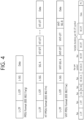
- FIG. 4 illustrates an example of a PPDU used in an IEEE standard.
- An RU may include a plurality of subcarriers (or tones).
- An RU may be used to transmit a signal to a plurality of STAs according to OFDMA. Further, an RU may also be defined to transmit a signal to one STA.
- An RU may be used for an STF, an LTF, a data field, or the like.
- a 484-RU may be used.
- the specific number of RUs may be changed similarly to FIG. 5 .
- a 26-RU, a 52-RU, a 106-RU, a 242-RU, a 484-RU, a 996-RU, and the like may be used in an example of FIG. 7 .
- seven DC tones may be inserted in the center frequency, 12 tones may be used for a guard band in the leftmost band of the 80 MHz band, and 11 tones may be used for a guard band in the rightmost band of the 80 MHz band.
- a 26-RU corresponding to 13 tones on each of the left and right sides of the DC band may be used.
- a 996-RU may be used, in which case five DC tones may be inserted.
- an HE-SIG-B field 810 includes a common field 820 and a user-specific field 830.
- the common field 820 may include information commonly applied to all users (i.e., user STAs) which receive SIG-B.
- the user-specific field 830 may be called a user-specific control field. When the SIG-B is transferred to a plurality of users, the user-specific field 830 may be applied only any one of the plurality of users.
- the common field 820 and the user-specific field 830 may be separately encoded.
- the common field 820 may include RU allocation information of N*8 bits.
- the RU allocation information may include information related to a location of an RU.
- the RU allocation information may include information related to a specific frequency band to which a specific RU (26-RU/52-RU/106-RU) is arranged.
- up to nine 26-RUs may be allocated to the 20 MHz channel.
- the RU allocation information of the common field 820 is set to "00000000" as shown in Table 1
- the nine 26-RUs may be allocated to a corresponding channel (i.e., 20 MHz).
- the RU allocation information of the common field 820 is set to "00000001" as shown in Table 1
- seven 26-RUs and one 52-RU are arranged in a corresponding channel. That is, in the example of FIG. 5 , the 52-RU may be allocated to the rightmost side, and the seven 26-RUs may be allocated to the left thereof.
- Table 1 shows only some of RU locations capable of displaying the RU allocation information.
- the RU allocation information may include an example of Table 2 below.
- Table 2 8 bits indices (B7 B6 B5 B4 B3 B2 B1 B0) #1 #2 #3 #4 #5 #6 #7 #8 #9 Number of entries 01000y 2 y 1 y 0 106 26 26 26 26 26 8 01001y 2 y 1 y 0 106 26 26 26 52 8
- "01000y2y1y0" relates to an example in which a 106-RU is allocated to the leftmost side of the 20 MHz channel, and five 26-RUs are allocated to the right side thereof.
- a plurality of STAs e.g., user-STAs
- a MU-MIMO scheme e.g., up to 8 STAs (e.g., user-STAs) may be allocated to the 106-RU, and the number of STAs (e.g., user-STAs) allocated to the 106-RU is determined based on 3-bit information (y2y1y0). For example, when the 3-bit information (y2y1y0) is set to N, the number of STAs (e.g., user-STAs) allocated to the 106-RU based on the MU-MIMO scheme may be N+1.
- a plurality of STAs (e.g., user STAs) different from each other may be allocated to a plurality of RUs.
- the plurality of STAs (e.g., user STAs) may be allocated to one or more RUs having at least a specific size (e.g., 106 subcarriers), based on the MU-MIMO scheme.
- the user-specific field 830 may include a plurality of user fields.
- the number of STAs (e.g., user STAs) allocated to a specific channel may be determined based on the RU allocation information of the common field 820. For example, when the RU allocation information of the common field 820 is "00000000", one user STA may be allocated to each of nine 26-RUs (e.g., nine user STAs may be allocated). That is, up to 9 user STAs may be allocated to a specific channel through an OFDMA scheme. In other words, up to 9 user STAs may be allocated to a specific channel through a non-MU-MIMO scheme.
- RU allocation when RU allocation is set to "01000y2y1y0", a plurality of STAs may be allocated to the 106-RU arranged at the leftmost side through the MU-MIMO scheme, and five user STAs may be allocated to five 26-RUs arranged to the right side thereof through the non-MU MIMO scheme. This case is specified through an example of FIG. 9 .
- FIG. 9 illustrates an example in which a plurality of user STAs are allocated to the same RU through a MU-MIMO scheme.
- a 106-RU may be allocated to the leftmost side of a specific channel, and five 26-RUs may be allocated to the right side thereof.
- three user STAs may be allocated to the 106-RU through the MU-MIMO scheme.
- the user-specific field 830 of HE-SIG-B may include eight user fields.
- the eight user fields may be expressed in the order shown in FIG. 9 .
- two user fields may be implemented with one user block field.
- the user fields shown in FIG. 8 and FIG. 9 may be configured based on two formats. That is, a user field related to a MU-MIMO scheme may be configured in a first format, and a user field related to a non-MIMO scheme may be configured in a second format. Referring to the example of FIG. 9 , a user field 1 to a user field 3 may be based on the first format, and a user field 4 to a user field 8 may be based on the second format.
- the first format or the second format may include bit information of the same length (e.g., 21 bits).
- Each user field may have the same size (e.g., 21 bits).
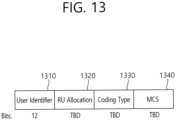
- the user field of the first format (the first of the MU-MIMO scheme) may be configured as follows.
- a first bit (i.e., B0-B10) in the user field may include identification information (e.g., STA-ID, partial AID, etc.) of a user STA to which a corresponding user field is allocated.
- a second bit (i.e., B11-B14) in the user field may include information related to a spatial configuration.
- an example of the second bit (i.e., B11-B14) may be as shown in Table 3 and Table 4 below.
- a third bit (i.e., B15-18) in the user field may include modulation and coding scheme (MCS) information.
- MCS modulation and coding scheme
- the MCS information may be applied to a data field in a PPDU including corresponding SIG-B.
- An MCS, MCS information, an MCS index, an MCS field, or the like used in the present specification may be indicated by an index value.
- the MCS information may be indicated by an index 0 to an index 11.
- the MCS information may include information related to a constellation modulation type (e.g., BPSK, QPSK, 16-QAM, 64-QAM, 256-QAM, 1024-QAM, etc.) and information related to a coding rate (e.g., 1/2, 2/3, 3/4, 5/6e, etc.).
- Information related to a channel coding type e.g., LCC or LDPC
- LCC long-coding code
- a fifth bit (e.g., B19) in the user field of the second format may include information related to whether dual carrier modulation (DCM) is applied.
- a sixth bit (i.e., B20) in the user field of the second format may include information related to a coding type (e.g., BCC or LDPC).
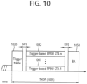
- the trigger frame of FIG. 11 may include a padding field 1170 and a frame check sequence field 1180.
- An HE-SIG-A information field 1240 may include information for controlling content of a SIG-A field (i.e., HE-SIG-A field) of the uplink PPDU in response to the corresponding trigger frame.
- the trigger type field 1260 of the trigger frame in the present specification indicates a trigger frame of a basic type for typical triggering.
- the trigger frame of the basic type may be referred to as a basic trigger frame.
- the STA1 of FIG. 14 is an associated STA
- the total number of eligible RA RUs for the STA1 is 3 (RU 1, RU 2, and RU 3), and thus the STA1 decreases an OBO counter by 3 so that the OBO counter becomes 0.
- the STA2 of FIG. 14 is an associated STA
- the total number of eligible RA RUs for the STA2 is 3 (RU 1, RU 2, and RU 3), and thus the STA2 decreases the OBO counter by 3 but the OBO counter is greater than 0.
- the STA3 of FIG. 14 is an un-associated STA
- the total number of eligible RA RUs for the STA3 is 2 (RU 4, RU 5), and thus the STA3 decreases the OBO counter by 2 but the OBO counter is greater than 0.
- FIG. 15 illustrates an example of a channel used/supported/defined within a 2.4 GHz band.
- the 2.4 GHz band may be called in other terms such as a first band.
- the 2.4 GHz band may imply a frequency domain in which channels of which a center frequency is close to 2.4 GHz (e.g., channels of which a center frequency is located within 2.4 to 2.5 GHz) are used/supported/defined.
- the 5 GHz band may be called in other terms such as a second band or the like.
- the 5 GHz band may imply a frequency domain in which channels of which a center frequency is greater than or equal to 5 GHz and less than 6 GHz (or less than 5.9 GHz) are used/supported/defined.
- the 5 GHz band may include a plurality of channels between 4.5 GHz and 5.5 GHz. A specific numerical value shown in FIG. 16 may be changed.
- a plurality of channels may be configured within the 5 GHz band, and a bandwidth of each channel may be variously set to, for example, 20 MHz, 40 MHz, 80 MHz, 160 MHz, or the like.
- 5170 MHz to 5330 MHz frequency domains/ranges within the UNII-1 and UNII-2 may be divided into eight 20 MHz channels.
- the 5170 MHz to 5330 MHz frequency domains/ranges may be divided into four channels through a 40 MHz frequency domain.
- the 5170 MHz to 5330 MHz frequency domains/ranges may be divided into two channels through an 80 MHz frequency domain.
- the 5170 MHz to 5330 MHz frequency domains/ranges may be divided into one channel through a 160 MHz frequency domain.
- the 6 GHz band may be called in other terms such as a third band or the like.
- the 6 GHz band may imply a frequency domain in which channels of which a center frequency is greater than or equal to 5.9 GHz are used/supported/defined.
- a specific numerical value shown in FIG. 17 may be changed.
- the 20 MHz channel of FIG. 17 may be defined starting from 5.940GHz.
- the leftmost channel may have an index 1 (or a channel index, a channel number, etc.), and 5.945 GHz may be assigned as a center frequency. That is, a center frequency of a channel of an index N may be determined as (5.940 + 0.005*N) GHz.
- an index (or channel number) of the 2 MHz channel of FIG. 17 may be 1, 5, 9, 13, 17, 21, 25, 29, 33, 37, 41, 45, 49, 53, 57, 61, 65, 69, 73, 77, 81, 85, 89, 93, 97, 101, 105, 109, 113, 117, 121, 125, 129, 133, 137, 141, 145, 149, 153, 157, 161, 165, 169, 173, 177, 181, 185, 189, 193, 197, 201, 205, 209, 213, 217, 221, 225, 229, 233.
- an index of the 40 MHz channel of FIG. 17 may be 3, 11, 19, 27, 35, 43, 51, 59, 67, 75, 83, 91, 99, 107, 115, 123, 131, 139, 147, 155, 163, 171, 179, 187, 195, 203, 211, 219, 227.
- L-LTF and L-STF may be the same as the fields of the prior art (or related art).
- the transmitting STA may generate an RL-SIG, which is generated identically as the L-SIG.
- the receiving STA may know that the reception PPDU is an HE PPDU or EHT PPDU based on the presence (or existence) of an RL-SIG.
- the U-SIG may include N-bit information and may also include information for identifying the EHT PPDU type.
- the U-SIG may be configured based on 2 symbols (e.g., two contiguous OFDM symbols). Each symbol (e.g., OFDM symbol) for the U-SIG may have a duration of 4 us.
- Each symbol of the U-SIG may be used for transmitting 26-bit information. For example, each symbol of the U-SIG may be transmitted/received based on 52 data tones and 4 pilot tones.
- the version-independent bits of the U-SIG may include information related to the length of a TXOP, and information related to BSS color ID.
- EHT PPDU related to SU mode EHT PPDU related to MU mode
- EHT PPDU related to a Trigger Frame EHT PPDU related to Extended Range transmission, and so on
- information related to the EHT PPDU type may be included in the version-dependent bits of the U-SIG.
- the U-SIG and EHT-SIG may include information related to preamble puncturing based on the following method.
- the U-SIG may be separately configured in 80 MHz units. For example, when the bandwidth of a PPDU is 160 MHz, a first U-SIG for a first 80 MHz band and a second U-SIG for a second 80 MHz band may be included in the corresponding PPDU.
- a first field of the first U-SIG may include information related to the 160 MHz bandwidth
- a second field of the first U-SIG may include information related to preamble puncturing (i.e., information related to a preamble puncturing pattern) that is applied to the first 80 MHz band
- a first field of the second U-SIG may include information related to the 160 MHz bandwidth
- a second field of the second U-SIG may include information related to preamble puncturing (i.e., information related to a preamble puncturing pattern) that is applied to the second 80 MHz band.
- the U-SIG and EHT-SIG may include information related to preamble puncturing based on the following method.
- the U-SIG may include information related to preamble puncturing (i.e., information related to a preamble puncturing pattern) for all bands. That is, the EHT- SIG may not include information related to preamble puncturing, and only the U-SIG may include information related to preamble puncturing (i.e., information related to a preamble puncturing pattern).
- the U-SIG may be configured of 20 MHz units. For example, when an 80 MHz PPDU is configured, the U-SIG may be duplicated. That is, 4 identical U-SIGs may be included in the 80 MHz PPDU. A PPDU that exceeds the 80 MHz bandwidth may include different U-SIGs.
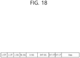
- the EHT-SIG of FIG. 18 may include the technical features of an HE-SIG-B, which is indicated in the examples of FIG. 8 to FIG. 9 , as they are.
- the EHT-SIG may also be referred to by using various terms, such as a second SIG field, a second SIG, a second-type SIG, a control signal, a control signal field, a second (type) control signal, and so on.
- the EHT-SIG may include N-bit information (e.g., 1-bit information) related to whether an EHT PPDU supports the SU mode or whether an EHT PPDU supports the MU mode.
- N-bit information e.g., 1-bit information
- the EHT-SIG may be configured based on various MCS schemes. As described above, the information related to the MCS scheme being applied to the EHT-SIG may be included in the U-SIG.
- the EHT-SIG may be configured based on a DCM scheme. For example, among N number of data tones (e.g., 52 data tones) that are allocated for the EHT-SIG, a first modulation scheme may be applied to one half of contiguous tones, and a second modulation scheme may be applied to the remaining half of contiguous tones. That is, the transmitting STA may modulate specific control information to a first symbol based on the first modulation scheme and may allocate the modulated first symbol to one half of contiguous tones.
- N number of data tones e.g., 52 data tones
- the transmitting STA may modulate the same control information to a second symbol based on the second modulation scheme and may allocated the modulated second symbol to the other half of contiguous tones.
- information related to whether or not the DCM scheme is applied to the EHT-SIG e.g., 1 bit field
- EHT-STF of FIG. 18 may be used for enhancing automatic gain control estimation in a multiple input multiple output (MIMO) environment or OFDMA environment.
- EHT-LTF of FIG. 18 may be used for estimating a channel in a MIMO environment or OFDMA environment.
- the EHT-STF may be set to various types.
- a first type i.e., 1x STF
- An STF signal that is generated based on the first type STF sequence may have a periodicity (or cycle period) of 0.8 ⁇ s.
- the signal having the periodicity of 0.8 ⁇ s may be repeated 5 times and become a first type STF having a length of 4 ⁇ s.
- a second type (i.e., 2x STF) may be generated based on a second type STF sequence in which non-zero coefficients are positioned at 8 subcarrier spacings.
- An STF signal that is generated based on the second type STF sequence may have a periodicity (or cycle period) of 1.6 ⁇ s. And, the signal having the periodicity of 1.6 ⁇ s may be repeated 5 times and become a second type STF having a length of 8 ⁇ s.
- EHT-STF sequence for configuring an EHT-STF will be proposed. The following sequence may be modified to various types.
- An EHT-STF for a 20 MHz PPDU may be configured based on the following equation.
- the example shown below may be a first type (i.e., 1x STF) sequence.
- the first type sequence may be included in an EHT-PPDU and not a trigger-based (TB) PPDU.
- (a:b:c) may denote durations being defined at b tone spacings (i.e., subcarrier spacings) starting from an a tone index (i.e., subcarrier index) to a c tone index.
- Equation 2 shown below may represent a sequence that is defined at 16 tone spacings starting from tone index -112 to tone index 112.
- Equation 7 to Equation 11 relate to examples of a second type (i.e., 2x STF) sequence.
- EHT-STF ⁇ 120 : 8 : 120 M ,0 , ⁇ M * 1 + j /sqrt 2
- EHT-STF(-504:8:504) ⁇ M, 1, -M, -1, -M, -1, M, 0, -M, 1, M, 1, -M, 1, -M, 1, -M ⁇ *(1 + j)/sqrt(2)
- EHT-STF for a 160 MHz PPDU may be configured based on the following equation.
- EHT ⁇ STF ⁇ 1016 : 16 : 1016 M , ⁇ 1 , M , ⁇ 1 , ⁇ M , ⁇ 1 , M , 0 , ⁇ M , 1 , M , 1 , ⁇ M , 1 , ⁇ M , 0 , ⁇ M , 1 , ⁇ M , 1 , ⁇ M , 0 , ⁇ M , 1 , ⁇ M , 0 , ⁇ M , 1 , M , 1 ⁇ M , 1 ⁇ M * 1 + j / sqrt 2
- a sequence for a lower 80 MHz may be the same as Equation 9.
- a sequence for a higher 80 MHz may be configured based on the following equation.
- EHT-STF(-504:8:504) ⁇ -M, 1, -M, 1, M, 1, -M, 0, -M, 1, M, 1, -M, 1, -M ⁇ *(1 + j)/sqrt(2)
- EHT ⁇ STF ⁇ 504 0
- EHT ⁇ STF 504 0
- An EHT-LTF may have first, second, and third types (i.e., 1x, 2x, 4x LTF).
- the first/second/third type LTF may be generated based on an LTF sequence in which non-zero coefficients are positioned at 4/2/1 subcarrier spacing(s).
- the first/second/third type LTF may have a time length of 3.2/6.4/12.8 ⁇ s.
- various lengths of GI e.g., 0.8/1/6/3.2 ⁇ s may be applied to the first/second/third type LTF.
- Information related to an STF and/or LTF type may be included in an SIG A field and/or SIG B field of FIG. 18 .
- the PPDU (i.e., EHT-PPDU) of FIG. 18 may be configured based on examples of FIG. 5 and FIG. 6 .
- an EHT PPDU being transmitted over a 20 MHz band i.e., a 20 MHz EHT PPDU
- a 20 MHz EHT PPDU may be configured based on RUs of FIG. 5 . That is, the location of an RU of the EHT-STF, EHT-LTF, data field being included in the EHT PPDU may be determined as shown in FIG. 5 .
- An EHT PPDU being transmitted over a 40 MHz band i.e., a 40 MHz EHT PPDU, may be configured based on RUs of FIG. 6 . That is, the location of an RU of the EHT-STF, EHT-LTF, data field being included in the EHT PPDU may be determined as shown in FIG. 6 .
- a tone plan for 80 MHz may be determined. That is, an 80 MHz EHT PPDU may be transmitted based on a new tone plan in which the RU of FIG. 6 is repeated two times, and not the RU of FIG. 7 .
- 23 tones i.e., 11 guard tones + 12 guard tones
- a tone plan for an 80 MHz EHT PPDU being allocated based on OFDMA may have 23 DC tones.
- an 80 MHz EHT PPDU being allocated based on non-OFDMA i. e., non-OFDMA full Bandwidth 80 MHz PPDU
- 996 RUs may include 5 DC tones, 12 left-guard tones, and 11 right-guard tones.
- a tone plan for 160/240/320 MHz may be configured to have a format of repeating the pattern of FIG. 6 multiple times.
- the PPDU of FIG. 18 may be determined (or identified) as an EHT PPDU based on the following method.
- a receiving STA may determine a type of an RX PPDU as the EHT PPDU, based on the following aspect.
- the RX PPDU may be determined as the EHT PPDU: 1) when a first symbol after an L-LTF signal of the RX PPDU is a BPSK symbol; 2) when RL-SIG in which the L-SIG of the RX PPDU is repeated is detected; and 3) when a result of applying "module 3" to a value of a length field of the L-SIG of the RX PPDU is detected as "0".
- the receiving STA may detect a type of the EHT PPDU (e.g., an SU/MU/Trigger-based/Extended Range type), based on bit information included in a symbol after the RL-SIG of FIG. 18 .
- a type of the EHT PPDU e.g., an SU/MU/Trigger-based/Extended Range type
- the receiving STA may determine the type of the RX PPDU as a non-HT, HT, and VHT PPDU, based on the following aspect.
- the RX PPDU may be determined as the non-HT, HT, and VHT PPDU: 1) when a first symbol after an L-LTF signal is a BPSK symbol; and 2) when RL-SIG in which L-SIG is repeated is not detected.
- the receiving STA detects that the RL-SIG is repeated, when a result of applying "modulo 3" to the length value of the L-SIG is detected as "0"
- the RX PPDU may be determined as the non-HT, HT, and VHT PPDU.
- a PPDU i.e., SU PPDU
- a PPDU i.e., MU PPDU
- respective tone plans are separately defined. Specific details will be described below.
- the N-tone RU may include a pre-set pilot tone.
- An OFDM symbol consists of subcarriers, and the number of subcarriers may function as a bandwidth of a PPDU.
- a data subcarrier used for data transmission a pilot subcarrier used for phase information and parameter tacking, and an unused subcarrier not used for data transmission and pilot transmission are defined.
- the 26-tone RU consists of 24 data subcarriers and 2 pilot subcarriers.
- the 52-tone RU consists of 48 data subcarriers and 4 pilot subcarriers.
- the 106-tone RU consists of 102 data subcarriers and 4 pilot subcarriers.
- the 242-tone RU consists of 234 data subcarriers and 8 pilot subcarriers.
- the 484-tone RU consists of 468 data subcarriers and 16 pilot subcarriers.
- the 996-tone RU consists of 980 data subcarriers and 16 pilot subcarriers.
- a null subcarrier exists between 26-tone RU, 52-tone RU, and 106-tone RU locations.
- the null subcarrier is located near a DC or edge tone to protect against transmit center frequency leakage, receiver DC offset, and interference from an adjacent RU.
- the null subcarrier has zero energy.
- An index of the null subcarrier is listed as follows.
- a null subcarrier location for each 80 MHz frequency segment of the 80+80 MHz HE PPDU shall follow the location of the 80 MHz HE PPDU.
- a location of a pilot sequence in an HE-LTF field and data field may be the same as a location of 4x HE-LTF.
- the location of the pilot sequence in HE-LTF is configured based on pilot subcarriers for a data field multiplied 4 times. If the pilot subcarrier exists in 2x HE-LTF, the location of the pilot subcarrier shall be the same as a location of a pilot in a 4x data symbol. All pilot subcarriers are located at even-numbered indices listed below.
- the location of the pilot subcarrier shall use the same 80 MHz location for 80 MHz of both sides.
- the MAC In order to transmit data, the MAC generates a PHY-TXSTART.request primitive, which causes a PHY entity to enter a transmit state. Additionally, the PHY is configured to operate in an appropriate frequency via station management through PLME. Other transmission parameters, such as HE-MCS, coding type, and transmission power are configured through a PHY-SAP by using a PHY-TXSTART.request(TXVECTOR) primitive.
- a MAC sublayer may issue a PHY-TRIGGER.request together with a TRIGVECTOR parameter, which provides information needed for demodulating an HE TB PPDU response that is expected of the PHY entity.
- the PHY entity After a PHY preamble transmission is started, the PHY entity immediately initiates data scrambling and data encoding.
- An encoding method for the data field is based on FEC_CODING, CH BANDWIDTH, NUM_STS, STBC, MCS, and NUM_USERS parameters of the TXVECTOR.
- a SERVICE field and a PSDU are encoded in a transmitter (or transmitting device) block diagram, which will be described later on.
- Data should be exchanged between the MAC and the PHY through a PHY-DATA.request(DATA) primitive that is issued by the MAC and PHY-DATA.confirm primitives that are issued by the PHY
- a PHY padding bit is applied to the PSDU in order to set a number of bits of the coded PSDU to be an integer multiple of a number of coded bits per OFDM symbol.
- the transmission is swiftly (or quickly) ended by the MAC through a PHY-TXEND.request primitive.
- the PSDU transmission is ended upon receiving a PHY-TXEND.request primitive.
- Each PHY-TXEND.request primitive mat notify its reception together with a PHY-TXEND.confirm primitive from the PHY.
- a packet extension and/or a signal extension may exist in a PPDU.
- a PHY-TXEND.confirm primitive is generated at an actual end time of a most recent PPDU, an end time of a packet extension, and an end time of a signal extension.
- GI Guard Interval
- FIG. 20 shows an example of a block diagram of a transmitting device for generating each field of an HE PPDU.
- the encoded data bit sequence that is encoded by the LDPC encoder is divided into multiple spatial streams by a stream parser.
- an encoded data bit sequence that is divided into each spatial stream may be referred to as a spatial block.
- a number of the spatial blocks may be determined by a number of spatial streams that are used for transmitting an PPDU, and the number of spatial blocks may be set to be equal to the number of spatial blocks.
- LDPC tone mapping for an LDPC-coded stream related to a user u may be performed, as shown below, by substituting a stream of complex numbers generated by a constellation mapper.
- d " t k , i , n , l , u d ′ k , i , n , l , u ;
- k 0,1 , ... , N SD ⁇ 1 for 20 MHz, 40 MHz, 80 MHz and 80+80 MHz;
- k 0,1 , ... , N ⁇ SD 2 ⁇ 1 ⁇ for 160 MHz;
- LDPC tone mapping for an LDPC-coded stream related to a user u may be performed, as shown below, by substituting a stream of complex numbers generated by a constellation mapper.
- the DCM scheme may be applied only to a data field and/or SIG-B field of an HE PPDU. Additionally, the DCM scheme may be used or may not be used in the transmitting device (optional feature).
- a complex constellation number d k , i , n , l , r , u ′ that is outputted from the constellation mapper may obtain a complex constellation number d t k , i , n , l , r , u " that is outputted via LDPC tone mapping, which is similar to the interleaving operation.
- the d k , i , n , l , r , u ′ along with d t k , i , n , l , r , u " is mapped in data tones that are spaced apart by D TM - 1 . That is, as a result of the LDPC tone mapping operation, each of the two serially (or consecutively) generated complex constellation numbers may be transmitted from two data tones each being spaced apart by D TM - 1 , respectively.
- FIG. 24 shows an example of LDPC tone mapping being performed by applying DCM for a 106-tone RU.
- k is a constellation mapped tone index that is outputted from the constellation mapper
- t(k) is an LDPC tone mapped tone index that is outputted from the LDPC tone mapper.
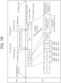
- the U-SIG of FIG. 18 is composed of version-independent fields and version-dependent fields. Also, U-SIG consists of two symbols that are jointly encoded, and each 20 MHz consists of 52 data tones and 4 pilot tones. Also, the U-SIG field is modulated in the same way as HE-SIG-A.
- the EHT-SIG may be divided into a common field and a user-specific field and may be encoded according to a variable MCS. The information for allocating RUs may be carried in the common field and the user-specific field.
- the LDPC tone mapping method may be defined as follows.
- N SD , D TM , and D TM_DCM in each RU are as follows.
- the N SD , D TM , and D TM_DCM for each RU size described above may be used without modification.
- frequency diversity may be obtained by applying LDPC tone mapping for each RU of a Multi-RU allocated using the existing equations below.
- d " t k , i , n , l , r , u d ′ k , i , n , l , r , u
- k ⁇ 0,1 , ... , N SD ⁇ 1 for a 26 ⁇ , 52 ⁇ , 106 ⁇ , 242 ⁇ , 484 ⁇ and 996 ⁇ tone RU 0,1 , ... , N SD / 2 ⁇ 1 for a 2 ⁇ 996 ⁇ tone RU
- t k ⁇ D TM _ DCM k mod N SD / 2 D TM _ DCM + ⁇ k ⁇ D TM _ DCM N SD / 2 ⁇ , for 0 ⁇ k ⁇ N SD / 2 D TM _ DCM k ⁇ N SD / 2 mod N SD / 2 D TM _ DCM + ⁇ k ⁇ N SD / 2 ⁇ D TM _ DCM N SD / 2 ⁇ + N SD / 2 , for N SD /2 ⁇ k ⁇ N SD
- the segment parser may not be applied, but the LDPC tone mapping may be performed as in the method of 4.2 described later by considering the Multi-RU to be one RU. For example, since the total size of the 242+484 tone RU is smaller than the 80 MHz band, it is not divided into each RU, and LDPC tone mapping is performed by considering the 242+484 tone RU to be one RU.
- the Multi-RU is not divided into each RU but is considered to be one RU for which LDPC tone mapping may be performed (the segment parser is not applied to the Multi-RU).
- N SD , D TM , and D TM_DCM in the Multi-RU may be defined.
- N SD , D TM , and D TM_DCM in the Multi-RU may be defined.
- scheduling, signaling, and hardware complexity for the combination are increased. Therefore, only two RUs may be allocated to one STA, and a Multi-RU (or a New RU) formed by a combination of two RUs and N SD , D TM , and D TM_DCM in the Multi-RU (or New RU) are proposed as follows.
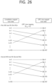
- FIG. 25 shows an example of LDPC tone mapping having tone spacing set to 18 in a 242 + 484 tone RU in a situation where DCM is not applied.
- FIG. 25 shows an example in which LDPC tone mapping is performed on a 242 + 484 tone RU.
- k represents a constellation mapped tone index output from the constellation mapper
- t(k) represents an LDPC tone mapped tone index output from the LDPC tone mapper.
- a complex constellation number d k , i , n , l , r , u ′ output from the constellation mapper may obtain a complex constellation number d t k , i , n , l , r , u " output via LDPC tone mapping, which is similar to the interleaving operation.
- the d k , i , n , l , r , u ′ along with d t k , i , n , l , r , u " are mapped in data tones spaced apart by D TM - 1. That is, as a result of the LDPC tone mapping operation, two consecutively generated complex constellation numbers may be transmitted from two data tones separated from each other by D TM - 1.
- FIG. 27 is a flow diagram illustrating the operation of a transmitting apparatus according to the present embodiment.
- the signal/field/sequence configured according to the present disclosure may be transmitted in the form of FIG. 18 .
- the memory 112 may store information on a plurality of tone plans/RUs according to the present disclosure.
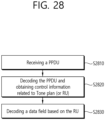
- FIG. 28 is a flow diagram illustrating the operation of a receiving apparatus according to the present embodiment.
- a receiving apparatus may perform the example of FIG. 28 .
- a receiving STA or a receiving apparatus may perform the example of FIG. 28 . Part of the steps (or specific sub-steps to be described later) in the example of FIG. 28 may be omitted or modified.
- an AP and a non-AP STA may exchange capability information as to whether each STA supports LDPC tone mapping.
- a beacon, a probe request, a probe response, an association request, an association response, other management frames, other control frames, or the MAC header of a general data PPDU may include the capability information as to whether LDPC tone mapping is supported.
- Sub-steps of the S2810 step may be determined based on the S2730 step.
- the S2810 step may perform an operation of restoring the results of the CSD, spatial mapping, IDFT/IFFT, and GI insert operations applied in the S2730 step.
- the receiving apparatus may perform decoding on the whole/part of the PPDU. Also, the receiving apparatus may obtain control information related to the tone plan (namely, RU) or sounding from the decoded PPDU.
- the receiving apparatus may decode the remaining part of the PPDU based on the information on the tone plan (namely, RU) obtained through the S2820 step. For example, the receiving STA may decode the STF/LTF field of the PPDU based on the information on the tone plan (namely, RU). Also, the receiving STA may decode the data field of the PPDU based on the information on the tone plan (namely, the RU) and obtain the MPDU included in the data field.
- the PPDU that is received through the transceiver 123 may be stored in the memory 122.
- the processor 121 may process decoding on the received PPDU through the memory 122.
- the processor 121 may obtain control information related to the tone-plan/RU included in the PPDU and may store the obtained control information in the memory 112.
- FIG. 29 may be performed in a network supporting the next-generation wireless LAN system (the IEEE 802.11be or EHT wireless LAN system).
- the next-generation wireless LAN system is an improved version of the 802.11ax system and may satisfy backward compatibility with the 802.11ax system.
- a transmitting STA may perform one example of FIG. 29 , and the transmitting STA may correspond to an access point (AP).
- the receiving STA of FIG. 29 may correspond to an STA that supports an Extremely High Throughput (EHT) wireless LAN system.
- EHT Extremely High Throughput
- a transmitting station (STA) generates a Physical Protocol Data Unit (PPDU) that includes a data field.
- STA transmitting station
- PPDU Physical Protocol Data Unit
- the transmitting STA transmits the PPDU to a receiving STA.
- the Multi-RU may be allocated to the receiving STA (one STA) in a combination of various RUs.
- the first parameter may be determined according to the number of data tones in the Multi-RU.
- the first parameter may correspond to D TM , which is an LDPC tone mapping distance parameter.
- the D TM may be a tone interval used in LDPC tone mapping.
- the constellation mapping and the LDPC tone mapping may be performed for each frequency segment.
- one frequency segment may correspond to each RU of the Multi-RU. That is, if the segment parser is used in the transmitting STA, the Multi-RU may be divided into each RU, and LDPC tone mapping may be performed separately for each RU.
- the present embodiment does not perform LDPC tone mapping separately for each RU but proposes a method of performing LDPC tone mapping by considering the Multi-RU to be one RU.
- the embodiment above describes an operation in which the LDPC tone mapping is performed on the Multi-RU, and the data tones are distributed at tone intervals of the first parameter.
- DCM Dual Carrier Modulation
- the second parameter may correspond to D TM_DCM , which is the LDPC tone mapping distance parameter when the DCM method is applied.
- the D TM_DCM may be a tone spacing used for the LDPC tone mapping when DCM is applied.
- t(k) represents the index of the first data tone
- U TM-DCM represents the second parameter
- k represents the index of the tone to which the bitstream has been mapped
- N SD represents the number of data tones in the Multi-RU
- floor represents a rounding-down function.
- the 26 tone RU is a resource unit composed of 26 tones
- the 106 tone RU is a resource unit composed of 52 tones.
- the 26 tone RU and the 106 tone RU may be adjacent to each other or included within a 20 MHz channel.
- the bitstream may be modulated to a first modulation symbol based on the first constellation mapping and a second modulation symbol based on the second constellation mapping.
- the bit order of a first bit group for the second modulation symbol may be different from the bit order of a second bit group for the first modulation symbol (( B 4 k , B 4 k +1 , B 4k + 2 , B 4k + 3 ) ⁇ ( B 4 k +1 , B 4k , B 4 k +3 , B 4 k +2 )).
- the first and second bit groups may be included in the bitstream.
- the first modulation symbol may be mapped to the first data tone
- the second modulation symbol may be mapped to the second data tone.
- the 26 tone RU is a resource unit composed of 26 tones
- the 106 tone RU is a resource unit composed of 52 tones.
- the 26 tone RU and the 106 tone RU may be adjacent to each other or included within a 20 MHz channel.
- a memory 150 of FIG. 31 may be the same as the memory(s) 112 and 122 shown in FIG. 1 .
- the memory 150 of FIG. 31 may be a separate external memory that is different from the memory(s) 112 and 122 shown in FIG. 1 .
- the data field is received through a Multiple-Resource Unit (Multi-RU).
- Multi-RU Multiple-Resource Unit
- LDPC Low Density Parity Check
- the constellation mapping and the LDPC tone mapping may be performed for each frequency segment.
- one frequency segment may correspond to each RU of the Multi-RU. That is, if the segment parser is used in the transmitting STA, the Multi-RU may be divided into each RU, and LDPC tone mapping may be performed separately for each RU.
- the present embodiment does not perform LDPC tone mapping separately for each RU but proposes a method of performing LDPC tone mapping by considering the Multi-RU to be one RU.
- a PHY padding operation For each bitstream, 1) a PHY padding operation, 2) a scrambling operation, 3) an LDPC encoding operation, 4) a stream parsing operation that maps LDPC encoded bits to a specific spatial stream, and 5) a segment parsing operation that divides a Multi-RU into each frequency segment (each RU) may be performed (if required); and 6) the constellation mapping operation may be performed on the individual spatial streams and frequency segments, and 7) the LDPC tone mapping operation may be performed on the modulation symbols generated based on the constellation mapping.
- the transmitting STA performs the procedures 1) to 7) sequentially, and the present embodiment mainly describes the procedure 7).
- the first to second constellation mapping may be one of Binary Phase Shift Keying (BPSK), Quadrature Phase Shift Keying (QPSK), or 16-Quadrature Amplitude Modulation (QAM).
- BPSK Binary Phase Shift Keying
- QPSK Quadrature Phase Shift Keying
- QAM 16-Quadrature Amplitude Modulation
- the constellation mapping may be one of the BPSK, QPSK, 16-QAM, 64-QAM, 256-QAM, or 1024-QAM.
- the tone spacing for each of the first and second data tones may be set to the second parameter based on the LDPC tone mapping.
- the first and second data tones may be included in the data tone.
- the second parameter may be 13.
- the second parameter may correspond to D TM_DCM , which is the LDPC tone mapping distance parameter when the DCM method is applied.
- the D TM_DCM may be a tone spacing used for the LDPC tone mapping when DCM is applied.
- the first data tone may correspond to a lower halftone (or subcarrier k) on the frequency domain
- the second data tone may correspond to an upper half tone on the frequency domain (or subcarrier k+N/2).
- the tone may be used interchangeably with the subcarrier.
- t(k) represents the index of the first data tone
- D TM_DCM represents the second parameter
- k represents the index of the tone to which the bitstream has been mapped
- N SD represents the number of data tones in the Multi-RU
- floor represents a rounding-down function.
- t(k) represents the index of the second data tone
- D TM_DCM represents the second parameter
- k represents the index of the tone to which the bitstream has been mapped
- N SD represents the number of data tones in the Multi-RU
- floor represents a rounding-down function.
- the bitstream may be modulated to a first modulation symbol based on the first constellation mapping and a second modulation symbol based on the second constellation mapping.
- the first modulation symbol may be mapped to the first data tone, and the second modulation symbol may be mapped to the second data tone.
- the PPDU may include the Legacy-Signal (L-SIG) field, the Repeated Legacy-Signal (RL-SIG) field, the EHT-Short Training Field (STF), and the EHT-Long Training Field (LTF).
- L-SIG Legacy-Signal
- RL-SIG Repeated Legacy-Signal
- STF EHT-Short Training Field
- LTF EHT-Long Training Field
- the EHT-SIG field may include the EHT-SIG-A field and the EHT-SIG-B field.
- the EHT-SIG field may further include the EHT-SIG-C field.
- the foregoing technical features of the present specification are applicable to various applications or business models.
- the foregoing technical features may be applied for wireless communication of a device supporting artificial intelligence (AI).
- AI artificial intelligence
- An artificial neural network is a model used in machine learning and may refer to an overall problem-solving model that includes artificial neurons (nodes) forming a network by combining synapses.
- the artificial neural network may be defined by a pattern of connection between neurons of different layers, a learning process of updating a model parameter, and an activation function generating an output value.
- the artificial neural network may include an input layer, an output layer, and optionally one or more hidden layers. Each layer includes one or more neurons, and the artificial neural network may include synapses that connect neurons. In the artificial neural network, each neuron may output a function value of an activation function of input signals input through a synapse, weights, and deviations.
- a model parameter refers to a parameter determined through learning and includes a weight of synapse connection and a deviation of a neuron.
- a hyper-parameter refers to a parameter to be set before learning in a machine learning algorithm and includes a learning rate, the number of iterations, a mini-batch size, and an initialization function.
- Learning an artificial neural network may be intended to determine a model parameter for minimizing a loss function.
- the loss function may be used as an index for determining an optimal model parameter in a process of learning the artificial neural network.
- Machine learning may be classified into supervised learning, unsupervised learning, and reinforcement learning.
- Supervised learning refers to a method of training an artificial neural network with a label given for training data, wherein the label may indicate a correct answer (or result value) that the artificial neural network needs to infer when the training data is input to the artificial neural network.
- Unsupervised learning may refer to a method of training an artificial neural network without a label given for training data.
- Reinforcement learning may refer to a training method for training an agent defined in an environment to choose an action or a sequence of actions to maximize a cumulative reward in each state.
- the foregoing technical features may be applied to wireless communication of a robot.
- Robots may refer to machinery that automatically process or operate a given task with own ability thereof.
- a robot having a function of recognizing an environment and autonomously making a judgment to perform an operation may be referred to as an intelligent robot.
- Robots may be classified into industrial, medical, household, military robots and the like according uses or fields.
- a robot may include an actuator or a driver including a motor to perform various physical operations, such as moving a robot joint.
- a movable robot may include a wheel, a brake, a propeller, and the like in a driver to run on the ground or fly in the air through the driver.
- the foregoing technical features may be applied to a device supporting extended reality.
- Extended reality collectively refers to virtual reality (VR), augmented reality (AR), and mixed reality (MR).
- VR technology is a computer graphic technology of providing a real-world object and background only in a CG image
- AR technology is a computer graphic technology of providing a virtual CG image on a real object image
- MR technology is a computer graphic technology of providing virtual objects mixed and combined with the real world.
- MR technology is similar to AR technology in that a real object and a virtual object are displayed together.
- a virtual object is used as a supplement to a real object in AR technology, whereas a virtual object and a real object are used as equal statuses in MR technology.
- XR technology may be applied to a head-mount display (HMD), a head-up display (HUD), a mobile phone, a tablet PC, a laptop computer, a desktop computer, a TV, digital signage, and the like.
- HMD head-mount display
- HUD head-up display
- a device to which XR technology is applied may be referred to as an XR device.
- the claims recited in the present specification may be combined in a variety of ways.
- the technical features of the method claims of the present specification may be combined to be implemented as a device, and the technical features of the device claims of the present specification may be combined to be implemented by a method.
- the technical characteristics of the method claim of the present specification and the technical characteristics of the device claim may be combined to be implemented as a device, and the technical characteristics of the method claim of the present specification and the technical characteristics of the device claim may be combined to be implemented by a method.
Landscapes
- Engineering & Computer Science (AREA)
- Signal Processing (AREA)
- Computer Networks & Wireless Communication (AREA)
- Mobile Radio Communication Systems (AREA)
Priority Applications (1)
| Application Number | Priority Date | Filing Date | Title |
|---|---|---|---|
| EP25206834.1A EP4651621A3 (fr) | 2019-08-12 | 2020-07-21 | Procédé par lequel une multi-ru reçoit une ppdu mappée de tonalité de ldpc dans un système lan sans fil, et appareil |
Applications Claiming Priority (5)
| Application Number | Priority Date | Filing Date | Title |
|---|---|---|---|
| KR20190098153 | 2019-08-12 | ||
| KR20200010099 | 2020-01-28 | ||
| KR20200013937 | 2020-02-05 | ||
| PCT/KR2020/009608 WO2021029551A1 (fr) | 2019-08-12 | 2020-07-21 | Procédé de réception par une multi-ru de ppdu à mappage de tonalités ldpc dans un système lan sans fil, et appareil |
| EP20852417.3A EP4016904B1 (fr) | 2019-08-12 | 2020-07-21 | Procédé et appareil de réception d'une ppdu avec multi-ru et mappage de tonalités ldpc dans un système lan sans fil |
Related Parent Applications (2)
| Application Number | Title | Priority Date | Filing Date |
|---|---|---|---|
| EP20852417.3A Division EP4016904B1 (fr) | 2019-08-12 | 2020-07-21 | Procédé et appareil de réception d'une ppdu avec multi-ru et mappage de tonalités ldpc dans un système lan sans fil |
| EP20852417.3A Division-Into EP4016904B1 (fr) | 2019-08-12 | 2020-07-21 | Procédé et appareil de réception d'une ppdu avec multi-ru et mappage de tonalités ldpc dans un système lan sans fil |
Related Child Applications (2)
| Application Number | Title | Priority Date | Filing Date |
|---|---|---|---|
| EP25206834.1A Division EP4651621A3 (fr) | 2019-08-12 | 2020-07-21 | Procédé par lequel une multi-ru reçoit une ppdu mappée de tonalité de ldpc dans un système lan sans fil, et appareil |
| EP25206834.1A Division-Into EP4651621A3 (fr) | 2019-08-12 | 2020-07-21 | Procédé par lequel une multi-ru reçoit une ppdu mappée de tonalité de ldpc dans un système lan sans fil, et appareil |
Publications (4)
| Publication Number | Publication Date |
|---|---|
| EP4398531A2 true EP4398531A2 (fr) | 2024-07-10 |
| EP4398531A3 EP4398531A3 (fr) | 2024-10-23 |
| EP4398531B1 EP4398531B1 (fr) | 2025-11-12 |
| EP4398531C0 EP4398531C0 (fr) | 2025-11-12 |
Family
ID=74570672
Family Applications (3)
| Application Number | Title | Priority Date | Filing Date |
|---|---|---|---|
| EP20852417.3A Active EP4016904B1 (fr) | 2019-08-12 | 2020-07-21 | Procédé et appareil de réception d'une ppdu avec multi-ru et mappage de tonalités ldpc dans un système lan sans fil |
| EP25206834.1A Pending EP4651621A3 (fr) | 2019-08-12 | 2020-07-21 | Procédé par lequel une multi-ru reçoit une ppdu mappée de tonalité de ldpc dans un système lan sans fil, et appareil |
| EP24177299.5A Active EP4398531B1 (fr) | 2019-08-12 | 2020-07-21 | Procédé par lequel une multi-ru reçoit une ppdu mappée de tonalité de ldpc dans un système lan sans fil, et appareil |
Family Applications Before (2)
| Application Number | Title | Priority Date | Filing Date |
|---|---|---|---|
| EP20852417.3A Active EP4016904B1 (fr) | 2019-08-12 | 2020-07-21 | Procédé et appareil de réception d'une ppdu avec multi-ru et mappage de tonalités ldpc dans un système lan sans fil |
| EP25206834.1A Pending EP4651621A3 (fr) | 2019-08-12 | 2020-07-21 | Procédé par lequel une multi-ru reçoit une ppdu mappée de tonalité de ldpc dans un système lan sans fil, et appareil |
Country Status (6)
| Country | Link |
|---|---|
| US (3) | US12034533B2 (fr) |
| EP (3) | EP4016904B1 (fr) |
| JP (1) | JP7320667B2 (fr) |
| KR (2) | KR102762494B1 (fr) |
| CN (1) | CN114365435B (fr) |
| WO (1) | WO2021029551A1 (fr) |
Cited By (2)
| Publication number | Priority date | Publication date | Assignee | Title |
|---|---|---|---|---|
| EP4066425A1 (fr) * | 2019-11-27 | 2022-10-05 | Qualcomm Incorporated | Conception de paramètre d'analyse et d'entrelacement pour agrégation d'unité de ressource |
| US20230403126A1 (en) * | 2021-02-27 | 2023-12-14 | Huawei Technologies Co., Ltd. | Method for transmitting physical layer protocol data unit and communication apparatus |
Families Citing this family (16)
| Publication number | Priority date | Publication date | Assignee | Title |
|---|---|---|---|---|
| CN112821998A (zh) * | 2019-11-15 | 2021-05-18 | 华为技术有限公司 | 传输物理层协议数据单元的方法和装置 |
| US12284631B2 (en) * | 2019-12-05 | 2025-04-22 | Lg Electronics Inc. | Technique for allocating resource unit in wireless communication system |
| US11564243B2 (en) * | 2020-07-27 | 2023-01-24 | Newracom, Inc. | Signaling method for multiplexing different amendment devices in an enhanced wireless local area network |
| US12096275B2 (en) * | 2020-08-14 | 2024-09-17 | Newracom, Inc. | Padding method for aggregated PPDU in enhancement of IEEE 802.11AX |
| US12302306B2 (en) * | 2020-10-07 | 2025-05-13 | Intel Corporation | Model-assisted deep reinforcement learning based scheduling in wireless networks |
| US20220255690A1 (en) * | 2021-02-09 | 2022-08-11 | Mediatek Singapore Pte. Ltd. | Signaling For UL TB PPDU With Distributed-Tone Resource Units In 6GHz Low-Power Indoor Systems |
| CN114978250A (zh) * | 2021-02-23 | 2022-08-30 | 华为技术有限公司 | 基于循环移位分集进行通信的方法和装置 |
| US12192127B2 (en) | 2021-03-26 | 2025-01-07 | Mediatek Singapore Pte. Ltd. | Distributed-tone RU on frequency subblock of wide-bandwidth PPDU |
| US11818698B2 (en) * | 2021-05-17 | 2023-11-14 | Qualcomm Incorporated | Distributed resource unit transmission |
| US11528093B1 (en) * | 2021-05-24 | 2022-12-13 | Qualcomm Incorporated | Forward-compatible puncturing indications |
| US11792062B2 (en) * | 2021-05-28 | 2023-10-17 | Huawei Technologies Co., Ltd. | Apparatus and method for wireless communication |
| JP7749345B2 (ja) * | 2021-06-02 | 2025-10-06 | キヤノン株式会社 | 通信装置、制御方法、及び、プログラム |
| CN115604849A (zh) * | 2021-07-12 | 2023-01-13 | 华为技术有限公司(Cn) | 一种通信方法及通信装置 |
| WO2023191362A1 (fr) * | 2022-03-29 | 2023-10-05 | 엘지전자 주식회사 | Procédé et dispositif d'attribution d'une pluralité de ru ou mru afin de transmettre ou de recevoir simultanément une pluralité de psdu par une sta de réception dans un système lan sans fil |
| EP4510487A1 (fr) * | 2022-04-14 | 2025-02-19 | LG Electronics Inc. | Procédé et dispositif pour une transmission ou une réception basée sur une attribution de tonalité pour une nouvelle numérologie dans un système lan sans fil |
| CN119342526A (zh) * | 2023-07-19 | 2025-01-21 | 华为技术有限公司 | 基于ppdu的通信方法及装置 |
Family Cites Families (27)
| Publication number | Priority date | Publication date | Assignee | Title |
|---|---|---|---|---|
| KR100837078B1 (ko) * | 2006-09-01 | 2008-06-12 | 주식회사 대우일렉트로닉스 | 저밀도 패리티 체크 부호를 이용한 광정보 기록장치 |
| US20130179755A1 (en) * | 2012-01-11 | 2013-07-11 | Qualcomm Incorporated | Systems and methods for low density parity check tone mapping |
| CN106664187A (zh) * | 2014-06-02 | 2017-05-10 | 马维尔国际贸易有限公司 | 高效正交频分复用(ofdm)物理层(phy) |
| US9894663B2 (en) | 2014-07-23 | 2018-02-13 | Qualcomm Incorporated | Systems and methods for improved communication efficiency in wireless networks |
| US10028284B2 (en) * | 2014-08-14 | 2018-07-17 | Qualcomm Incorporated | Systems and methods for improved communication efficiency in wireless networks |
| US9844028B2 (en) | 2014-08-15 | 2017-12-12 | Qualcomm Incorporated | Systems and methods for improved communication efficiency in wireless networks |
| WO2016085286A1 (fr) | 2014-11-27 | 2016-06-02 | 엘지전자 주식회사 | Procédé et dispositif pour la transmission de données sur la base de différents modèles de tonalité pilote dans un réseau lan sans fil |
| CN107210987B (zh) * | 2015-02-04 | 2020-06-30 | Lg电子株式会社 | 在无线通信系统中用于多用户发送和接收的方法及其装置 |
| WO2016167561A1 (fr) * | 2015-04-14 | 2016-10-20 | 엘지전자 주식회사 | Procédé et appareil pour configurer un champ de signal utilisé pour multiples unités de ressource dans un système lan sans fil |
| US20160323060A1 (en) * | 2015-04-28 | 2016-11-03 | Intel IP Corporation | Apparatus, computer readable medium, and method for higher qam in a high efficiency wireless local-area network |
| US10111270B2 (en) * | 2015-05-26 | 2018-10-23 | Lg Electronics Inc. | Method and apparatus for receiving signal by using resource units in a wireless local area system |
| WO2016201739A1 (fr) * | 2015-06-16 | 2016-12-22 | 华为技术有限公司 | Procédé de programmation de ressource, appareil, et dispositif |
| EP3337073B1 (fr) * | 2015-08-10 | 2021-05-05 | LG Electronics Inc. | Procédé et dispositif destinés à la formation d'un champ de commande comprenant des informations sur des unités de ressource dans un système lan sans fil |
| US10129001B2 (en) * | 2015-08-14 | 2018-11-13 | Newracom, Inc. | Block acknowledgment for multi-user transmissions in WLAN systems |
| US10536196B2 (en) | 2015-09-11 | 2020-01-14 | Interdigital Patent Holdings, Inc. | Multiple resource unit allocation for OFDMA WLAN |
| US10211948B2 (en) * | 2015-10-12 | 2019-02-19 | Mediatek Inc. | LDPC tone mapping schemes for dual-sub-carrier modulation in WLAN |
| US10110406B2 (en) | 2015-10-30 | 2018-10-23 | Qualcomm Incorporated | Systems and methods for channel interleaving in wireless networks |
| US10728861B2 (en) | 2017-10-11 | 2020-07-28 | Qualcomm Incorporated | Spectral mask and flatness for wireless local area networks |
| US10798712B2 (en) * | 2018-05-04 | 2020-10-06 | Intel Corporation | Methods for vehicular communication in accordance with co-existence between next generation vehicle-to-everything (NGV) devices and legacy devices |
| US11677499B2 (en) * | 2018-10-25 | 2023-06-13 | Mediatek Singapore Pte. Ltd. | Tone interleaving methods for multi-bands and wide bandwidth transmissions in WLAN |
| US11394492B2 (en) * | 2019-04-02 | 2022-07-19 | Newracom, Inc. | Binary convolutional coding (BCC) interleaver, dual sub-carrier modulation (DCM) constellation mapper, and low-density parity-check (LDPC) tone mapper design |
| US11398886B2 (en) * | 2019-07-12 | 2022-07-26 | Newracom, Inc. | Midamble operation in a wireless local area network |
| US11601219B2 (en) * | 2019-12-20 | 2023-03-07 | Mediatek Singapore Pte. Ltd. | Interleaving of combinations of multiple resource units in WLAN |
| US11711786B2 (en) * | 2020-01-21 | 2023-07-25 | Mediatek Singapore Pte. Ltd. | Optimization of resource unit and segment parser design for aggregated and multi-resource unit operations in extreme high-throughput systems |
| US11641254B2 (en) * | 2020-03-09 | 2023-05-02 | Apple Inc. | Multi-resource-unit aggregation |
| EP4152660A4 (fr) * | 2020-07-01 | 2023-11-29 | LG Electronics, Inc. | Procédé et appareil de réception d'une ppdu dans laquelle des données sont dupliquées dans un système wlan |
| CN115997372B (zh) * | 2020-07-02 | 2025-06-24 | Lg电子株式会社 | 在无线局域网系统中接收其中数据被复制并应用相位旋转的ppdu的方法和装置 |
-
2020
- 2020-07-21 US US17/631,328 patent/US12034533B2/en active Active
- 2020-07-21 WO PCT/KR2020/009608 patent/WO2021029551A1/fr not_active Ceased
- 2020-07-21 KR KR1020227002035A patent/KR102762494B1/ko active Active
- 2020-07-21 EP EP20852417.3A patent/EP4016904B1/fr active Active
- 2020-07-21 KR KR1020257003036A patent/KR20250020730A/ko active Pending
- 2020-07-21 EP EP25206834.1A patent/EP4651621A3/fr active Pending
- 2020-07-21 EP EP24177299.5A patent/EP4398531B1/fr active Active
- 2020-07-21 CN CN202080064184.1A patent/CN114365435B/zh active Active
- 2020-07-21 JP JP2022508769A patent/JP7320667B2/ja active Active
-
2023
- 2023-04-10 US US18/132,696 patent/US11902020B2/en active Active
-
2024
- 2024-05-23 US US18/672,817 patent/US20240313888A1/en active Pending
Cited By (2)
| Publication number | Priority date | Publication date | Assignee | Title |
|---|---|---|---|---|
| EP4066425A1 (fr) * | 2019-11-27 | 2022-10-05 | Qualcomm Incorporated | Conception de paramètre d'analyse et d'entrelacement pour agrégation d'unité de ressource |
| US20230403126A1 (en) * | 2021-02-27 | 2023-12-14 | Huawei Technologies Co., Ltd. | Method for transmitting physical layer protocol data unit and communication apparatus |
Also Published As
| Publication number | Publication date |
|---|---|
| JP2022544933A (ja) | 2022-10-24 |
| EP4651621A2 (fr) | 2025-11-19 |
| US12034533B2 (en) | 2024-07-09 |
| EP4398531A3 (fr) | 2024-10-23 |
| JP7320667B2 (ja) | 2023-08-03 |
| US20220278771A1 (en) | 2022-09-01 |
| CN114365435B (zh) | 2024-01-23 |
| US20240313888A1 (en) | 2024-09-19 |
| EP4651621A3 (fr) | 2026-01-21 |
| EP4016904A4 (fr) | 2023-09-06 |
| KR20250020730A (ko) | 2025-02-11 |
| EP4398531B1 (fr) | 2025-11-12 |
| EP4016904A1 (fr) | 2022-06-22 |
| EP4016904B1 (fr) | 2024-07-10 |
| EP4016904C0 (fr) | 2024-07-10 |
| CN114365435A (zh) | 2022-04-15 |
| WO2021029551A1 (fr) | 2021-02-18 |
| US11902020B2 (en) | 2024-02-13 |
| KR102762494B1 (ko) | 2025-02-05 |
| KR20220024788A (ko) | 2022-03-03 |
| EP4398531C0 (fr) | 2025-11-12 |
| US20230246738A1 (en) | 2023-08-03 |
Similar Documents
| Publication | Publication Date | Title |
|---|---|---|
| EP4016904B1 (fr) | Procédé et appareil de réception d'une ppdu avec multi-ru et mappage de tonalités ldpc dans un système lan sans fil | |
| US11985687B2 (en) | Method and device for receiving PPDU having been subjected to LDPC tone mapping in broadband tone plan in wireless LAN system | |
| US12063112B2 (en) | Method and device for receiving PPDU, for which LDPC tone mapping has been performed, in wireless LAN system | |
| EP4016945B1 (fr) | Procédé et appareil de réception de ppdu dans une bande large dans un système wlan | |
| EP4089969B1 (fr) | Procédé et dispositif de réception de ppdu à travers une large bande dans un système de réseau local sans fil | |
| EP4064773B1 (fr) | Procédé et appareil de réception d'une ppdu par l'intermédiaire de multiples ru dans un système lan sans fil | |
| US20230327805A1 (en) | Method and apparatus for receiving ppdu on which bcc interleaving has been performed in multi-ru in wireless lan system | |
| US20230268934A1 (en) | Method and apparatus for receiving ppdu in which data is duplicated in wireless lan system | |
| US20230344572A1 (en) | Method and apparatus for receiving ppdu in which data is duplicated and to which phase rotation is applied in wireless lan system | |
| EP4325765A2 (fr) | Procédé et appareil de réception de ppdu dans un système lan sans fil | |
| EP4068883B1 (fr) | Procédé et dispositif de réception de ppdu par de multiples ru dans un système lan sans fil | |
| EP4064599B1 (fr) | Procédé et appareil permettant de recevoir une ppdu par l'intermédiaire de multiples ru dans un système lan sans fil | |
| US12052127B2 (en) | Method and apparatus for receiving PPDU via broadband in wireless LAN system |
Legal Events
| Date | Code | Title | Description |
|---|---|---|---|
| PUAI | Public reference made under article 153(3) epc to a published international application that has entered the european phase |
Free format text: ORIGINAL CODE: 0009012 |
|
| STAA | Information on the status of an ep patent application or granted ep patent |
Free format text: STATUS: REQUEST FOR EXAMINATION WAS MADE |
|
| 17P | Request for examination filed |
Effective date: 20240524 |
|
| AC | Divisional application: reference to earlier application |
Ref document number: 4016904 Country of ref document: EP Kind code of ref document: P |
|
| AK | Designated contracting states |
Kind code of ref document: A2 Designated state(s): AL AT BE BG CH CY CZ DE DK EE ES FI FR GB GR HR HU IE IS IT LI LT LU LV MC MK MT NL NO PL PT RO RS SE SI SK SM TR |
|
| REG | Reference to a national code |
Ref country code: DE Ref legal event code: R079 Free format text: PREVIOUS MAIN CLASS: H04L0027260000 Ref document number: 602020062316 Country of ref document: DE Ipc: H04L0005000000 |
|
| PUAL | Search report despatched |
Free format text: ORIGINAL CODE: 0009013 |
|
| AK | Designated contracting states |
Kind code of ref document: A3 Designated state(s): AL AT BE BG CH CY CZ DE DK EE ES FI FR GB GR HR HU IE IS IT LI LT LU LV MC MK MT NL NO PL PT RO RS SE SI SK SM TR |
|
| RIC1 | Information provided on ipc code assigned before grant |
Ipc: H04W 84/12 20090101ALI20240913BHEP Ipc: H04W 72/04 20230101ALI20240913BHEP Ipc: H04L 27/26 20060101ALI20240913BHEP Ipc: H04L 1/00 20060101ALI20240913BHEP Ipc: H04L 5/00 20060101AFI20240913BHEP |
|
| GRAP | Despatch of communication of intention to grant a patent |
Free format text: ORIGINAL CODE: EPIDOSNIGR1 |
|
| STAA | Information on the status of an ep patent application or granted ep patent |
Free format text: STATUS: GRANT OF PATENT IS INTENDED |
|
| RIC1 | Information provided on ipc code assigned before grant |
Ipc: H04W 84/12 20090101ALI20250502BHEP Ipc: H04W 72/04 20230101ALI20250502BHEP Ipc: H04L 27/26 20060101ALI20250502BHEP Ipc: H04L 1/00 20060101ALI20250502BHEP Ipc: H04L 5/00 20060101AFI20250502BHEP |
|
| INTG | Intention to grant announced |
Effective date: 20250605 |
|
| GRAS | Grant fee paid |
Free format text: ORIGINAL CODE: EPIDOSNIGR3 |
|
| GRAA | (expected) grant |
Free format text: ORIGINAL CODE: 0009210 |
|
| STAA | Information on the status of an ep patent application or granted ep patent |
Free format text: STATUS: THE PATENT HAS BEEN GRANTED |
|
| AC | Divisional application: reference to earlier application |
Ref document number: 4016904 Country of ref document: EP Kind code of ref document: P |
|
| AK | Designated contracting states |
Kind code of ref document: B1 Designated state(s): AL AT BE BG CH CY CZ DE DK EE ES FI FR GB GR HR HU IE IS IT LI LT LU LV MC MK MT NL NO PL PT RO RS SE SI SK SM TR |
|
| REG | Reference to a national code |
Ref country code: CH Ref legal event code: F10 Free format text: ST27 STATUS EVENT CODE: U-0-0-F10-F00 (AS PROVIDED BY THE NATIONAL OFFICE) Effective date: 20251112 Ref country code: GB Ref legal event code: FG4D |
|
| REG | Reference to a national code |
Ref country code: IE Ref legal event code: FG4D |
|
| REG | Reference to a national code |
Ref country code: DE Ref legal event code: R096 Ref document number: 602020062316 Country of ref document: DE |
|
| U01 | Request for unitary effect filed |
Effective date: 20251210 |
|
| U07 | Unitary effect registered |
Designated state(s): AT BE BG DE DK EE FI FR IT LT LU LV MT NL PT RO SE SI Effective date: 20251217 |
|
| PG25 | Lapsed in a contracting state [announced via postgrant information from national office to epo] |
Ref country code: ES Free format text: LAPSE BECAUSE OF FAILURE TO SUBMIT A TRANSLATION OF THE DESCRIPTION OR TO PAY THE FEE WITHIN THE PRESCRIBED TIME-LIMIT Effective date: 20251112 |
|
| PG25 | Lapsed in a contracting state [announced via postgrant information from national office to epo] |
Ref country code: NO Free format text: LAPSE BECAUSE OF FAILURE TO SUBMIT A TRANSLATION OF THE DESCRIPTION OR TO PAY THE FEE WITHIN THE PRESCRIBED TIME-LIMIT Effective date: 20260212 |
|
| PG25 | Lapsed in a contracting state [announced via postgrant information from national office to epo] |
Ref country code: HR Free format text: LAPSE BECAUSE OF FAILURE TO SUBMIT A TRANSLATION OF THE DESCRIPTION OR TO PAY THE FEE WITHIN THE PRESCRIBED TIME-LIMIT Effective date: 20251112 |
|
| PG25 | Lapsed in a contracting state [announced via postgrant information from national office to epo] |
Ref country code: RS Free format text: LAPSE BECAUSE OF FAILURE TO SUBMIT A TRANSLATION OF THE DESCRIPTION OR TO PAY THE FEE WITHIN THE PRESCRIBED TIME-LIMIT Effective date: 20260212 |
|
| PG25 | Lapsed in a contracting state [announced via postgrant information from national office to epo] |
Ref country code: IS Free format text: LAPSE BECAUSE OF FAILURE TO SUBMIT A TRANSLATION OF THE DESCRIPTION OR TO PAY THE FEE WITHIN THE PRESCRIBED TIME-LIMIT Effective date: 20260312 |
|
| PG25 | Lapsed in a contracting state [announced via postgrant information from national office to epo] |
Ref country code: PL Free format text: LAPSE BECAUSE OF FAILURE TO SUBMIT A TRANSLATION OF THE DESCRIPTION OR TO PAY THE FEE WITHIN THE PRESCRIBED TIME-LIMIT Effective date: 20251112 |