EP4398565A2 - Évitement de collision par vision artificielle dans des opérations de forage - Google Patents
Évitement de collision par vision artificielle dans des opérations de forage Download PDFInfo
- Publication number
- EP4398565A2 EP4398565A2 EP24164246.1A EP24164246A EP4398565A2 EP 4398565 A2 EP4398565 A2 EP 4398565A2 EP 24164246 A EP24164246 A EP 24164246A EP 4398565 A2 EP4398565 A2 EP 4398565A2
- Authority
- EP
- European Patent Office
- Prior art keywords
- processor
- images
- working space
- coordinates
- human
- Prior art date
- Legal status (The legal status is an assumption and is not a legal conclusion. Google has not performed a legal analysis and makes no representation as to the accuracy of the status listed.)
- Pending
Links
Images


Classifications
-
- G—PHYSICS
- G06—COMPUTING OR CALCULATING; COUNTING
- G06T—IMAGE DATA PROCESSING OR GENERATION, IN GENERAL
- G06T19/00—Manipulating three-dimensional [3D] models or images for computer graphics
-
- E—FIXED CONSTRUCTIONS
- E21—EARTH OR ROCK DRILLING; MINING
- E21B—EARTH OR ROCK DRILLING; OBTAINING OIL, GAS, WATER, SOLUBLE OR MELTABLE MATERIALS OR A SLURRY OF MINERALS FROM WELLS
- E21B19/00—Handling rods, casings, tubes or the like outside the borehole, e.g. in the derrick; Apparatus for feeding the rods or cables
-
- E—FIXED CONSTRUCTIONS
- E21—EARTH OR ROCK DRILLING; MINING
- E21B—EARTH OR ROCK DRILLING; OBTAINING OIL, GAS, WATER, SOLUBLE OR MELTABLE MATERIALS OR A SLURRY OF MINERALS FROM WELLS
- E21B41/00—Equipment or details not covered by groups E21B15/00 - E21B40/00
- E21B41/0021—Safety devices, e.g. for preventing small objects from falling into the borehole
-
- F—MECHANICAL ENGINEERING; LIGHTING; HEATING; WEAPONS; BLASTING
- F16—ENGINEERING ELEMENTS AND UNITS; GENERAL MEASURES FOR PRODUCING AND MAINTAINING EFFECTIVE FUNCTIONING OF MACHINES OR INSTALLATIONS; THERMAL INSULATION IN GENERAL
- F16P—SAFETY DEVICES IN GENERAL; SAFETY DEVICES FOR PRESSES
- F16P3/00—Safety devices acting in conjunction with the control or operation of a machine; Control arrangements requiring the simultaneous use of two or more parts of the body
- F16P3/12—Safety devices acting in conjunction with the control or operation of a machine; Control arrangements requiring the simultaneous use of two or more parts of the body with means, e.g. feelers, which in case of the presence of a body part of a person in or near the danger zone influence the control or operation of the machine
- F16P3/14—Safety devices acting in conjunction with the control or operation of a machine; Control arrangements requiring the simultaneous use of two or more parts of the body with means, e.g. feelers, which in case of the presence of a body part of a person in or near the danger zone influence the control or operation of the machine the means being photocells or other devices sensitive without mechanical contact
- F16P3/142—Safety devices acting in conjunction with the control or operation of a machine; Control arrangements requiring the simultaneous use of two or more parts of the body with means, e.g. feelers, which in case of the presence of a body part of a person in or near the danger zone influence the control or operation of the machine the means being photocells or other devices sensitive without mechanical contact using image capturing devices
-
- G—PHYSICS
- G06—COMPUTING OR CALCULATING; COUNTING
- G06V—IMAGE OR VIDEO RECOGNITION OR UNDERSTANDING
- G06V20/00—Scenes; Scene-specific elements
- G06V20/50—Context or environment of the image
- G06V20/52—Surveillance or monitoring of activities, e.g. for recognising suspicious objects
-
- G—PHYSICS
- G06—COMPUTING OR CALCULATING; COUNTING
- G06V—IMAGE OR VIDEO RECOGNITION OR UNDERSTANDING
- G06V40/00—Recognition of biometric, human-related or animal-related patterns in image or video data
- G06V40/10—Human or animal bodies, e.g. vehicle occupants or pedestrians; Body parts, e.g. hands
- G06V40/103—Static body considered as a whole, e.g. static pedestrian or occupant recognition
-
- G—PHYSICS
- G06—COMPUTING OR CALCULATING; COUNTING
- G06T—IMAGE DATA PROCESSING OR GENERATION, IN GENERAL
- G06T2210/00—Indexing scheme for image generation or computer graphics
- G06T2210/12—Bounding box
-
- G—PHYSICS
- G06—COMPUTING OR CALCULATING; COUNTING
- G06T—IMAGE DATA PROCESSING OR GENERATION, IN GENERAL
- G06T2210/00—Indexing scheme for image generation or computer graphics
- G06T2210/21—Collision detection, intersection
Definitions
- the instant disclosure relates to control systems in drilling operations. More specifically, this disclosure relates to a computer vision collision avoidance system in drilling operations.
- Oil and gas drilling operations have evolved over the years to include multiple automated tool subsystems.
- Automated tool subsystems aid in executing repetitive tasks on the drill floor including drilling, tripping, casing, and cementing.
- Tool automation optimizes the rate of penetration, makes hole quality more consistent, reduces operation time, improves overall drilling performance, and reduces the cost of drilling operations. More importantly, tool automation reduces the number of people required to work in and around the hazardous drill floor environment. The overwhelming majority of drilling operations are not fully automated, therefore some tasks are still performed by humans working alongside heavy drilling machinery.
- the automated tool subsystems pose new challenges for maintaining a safe operating environment where man and machine must share the same workspace.
- Collision avoidance is a component of automated tool subsystems that mitigates the possibility of two or more of these tools colliding with each other.
- the systems that attempt to mitigate tool collision are known by various names: anti-collision systems (ACS), collision avoidance systems (CAS), zone management systems (ZMS), but all share a common goal.
- ACS anti-collision systems
- CAS collision avoidance systems
- ZMS zone management systems
- a bounding box surrounds a tool in virtual space and establishes a volume occupied by the tool.
- the bounding box may also be axis-aligned, in which case the virtual space surrounding the tool changes dynamically as the tool appendages extend, rotate, retract, raise, lower, etc.
- a proximity zone surrounds the bounding box and defines a hazardous area around the tool.
- Collision avoidance systems monitor tool positions and movement, and predict a location of a moving tool. Collision avoidance systems will override automated tool operations to prevent a virtual overlap of the projected bounding boxes, i.e. a real-world tool collision.
- Drill floor personnel are a dynamic component of the drilling operation that are not monitored by existing tool collision avoidance systems. Collision avoidance between drill floor personnel and automated tools depends on the situational awareness of the rig hands (i.e., drill floor personnel). The avoidance of an automated tool presents an unnecessary distraction to a drill hand in an already hazardous environment.
- Collisions between tools and floor personnel may be mitigated with an automated collision avoidance system that visually tracks drill floor personnel and tools, and controls the tools based on the visual tracking to ensure that the tools operate without colliding with drill floor personnel.
- an automated visual collision avoidance system may improve conventional collision avoidance systems by adding another degree of freedom for the tracking and control of the tools based on visual information of the drill floor.
- a method may include collecting, with one or more image capturing devices, one or more images of a working space, and identifying, with a first processor, a first object based, at least in part, on the one or more images. The method may also include determining, with the first processor, coordinates of the first object based, at least in part, on the one or more images, wherein the determined coordinates of the first object are coordinates in a three-dimensional coordinate system.
- the method may further include generating, with the first processor, a virtual boundary enclosing the identified first object in the three-dimensional coordinate system based, at least in part, on the determined coordinates of the first object, wherein the virtual boundary specifies a volume in the working space that a second object in the working space should not occupy.
- the method may also include transmitting, with the first processor, to a second processor, coordinates in the three-dimensional coordinate system corresponding to the generated virtual boundary, wherein the second processor controls the second object to perform an operation in the working space that includes the first object without contacting the virtual boundary of the first object.
- the one or more image capturing devices 104a-104n may be configured to capture one or more images of a working space.
- an image capturing device such as any one or more of image capturing devices 104a-104n, may be a still image capturing device, such as a camera, a video capturing device, such as a video camera, or both a still image and video capturing device.
- one or more cameras with real time composite video feeds such as closed-circuit television (CCTV) cameras, may be positioned around the working space to serve as the one or more image capturing devices and to collect the one or more images.
- CCTV closed-circuit television
- the processors, automated tool subsystems, image capturing devices, data storage devices, and network communication systems described above may include the processors, automated tool subsystems, image capturing devices, data storage devices, and network communication systems described below with respect to FIGURES 2-5 . While the embodiments described herein have been described with reference to numerous specific details, one of ordinary skill in the art will recognize that the embodiments can be embodied in other specific forms without departing from the spirit of the embodiments. Thus, one of ordinary skill in the art would understand that the embodiments described herein are not to be limited by the foregoing illustrative details or interrelationships between embodiments.
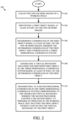
- FIGURE 2 is a flow chart illustrating a method 200 for automatically preventing a collision between objects according to one embodiment of the disclosure.
- a method 200 begins at block 202 with collecting one or more images of a working space.
- the one or more images may be collected with one or more image capturing devices, such as image capturing devices 104a-104n illustrated in FIGURE 1 .
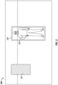
- the working space may include a drill floor with a plurality of humans and/or tools located in the working space.
- computer vision based on a real-time video feed of the working space, may be applied to a collision avoidance system in drilling operations to identify and track an individual and obtain an electronic representation of the individual's location on the drill floor.
- a plurality of CCTV cameras may be located around the drilling floor to provide continuous, real-time views of the drill floor working space.
- the CCTV camera signals may be transferred to a processing device and a memory device, such as CPU 108 and data storage device 110, respectively.
- the processing device may process the CCTV camera signals, either from the CCTV cameras or from the memory device, to generate a virtual drill floor working space that includes a spatial representation of drill floor personnel and tools within the drill floor working space.
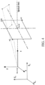
- FIGURE 5 is a diagram illustrating three two-dimensional images 502a-502c taken by three cameras, and the resulting bounding cylinder projected over an individual following processing by a processor, such as CPU 108, of the three two-dimensional images 502a-502c according to one embodiment of the disclosure.
- Multiple cameras may be positioned at various locations on a drill floor working space 500 to create an over-determined solution for the bounding box 506 of an individual 504 in the working space 500.
- image 502a is the image captured with a camera located at focal point 508.
- Images 502b-502c are examples of other images that may be captured with two other cameras positioned around the drill floor working space 500.
- Each camera may have a calibration matrix (K), camera center in world coordinates (e), and a camera orientation (R) value associated with it.
- P i K i R i I
- the CPU may transmit the coordinates corresponding to the generated virtual boundary to one or more processors, such as one or more processors of the automated tool subsystem 102, and the one or more processors may control one or more tools on the drill floor in order to prevent the one or more tools on the drill floor from colliding with one another or with a human on the drill floor.
- processors such as one or more processors of the automated tool subsystem 102
- the virtual boundary's static and dynamic extents corresponding to the object on the drill floor and generated by a first processor, such as CPU 108, may be transferred from the first processor to a collision avoidance system, such as automated tool subsystem 102, over a field-bus protocol, for example via network 106, and the collision avoidance system may, with a second processor, control tools on the drill floor such that they do not collide with the virtual boundary for the object.
- a collision avoidance system such as automated tool subsystem 102
- the collision avoidance system may, with a second processor, control tools on the drill floor such that they do not collide with the virtual boundary for the object.
- the projected virtual boundaries for objects may provide the collision avoidance system with the real time positional information for object's.
- a processor such as CPU 108, may be used to identify a unique identity of the human based, at least in part, on the one or more images.
- the computer vision collision avoidance system may employ a processor to perform feature recognition to identify an individual.
- the one or more images of the identified human may be compared with a plurality of stored images of humans, such as a plurality of images of humans stored in data storage device 110, until features corresponding to the identified human match features of a human in one of the plurality of stored images of humans.
- the features may be facial features or any other physical features unique to an individual.
Landscapes
- Engineering & Computer Science (AREA)
- Physics & Mathematics (AREA)
- Life Sciences & Earth Sciences (AREA)
- Mining & Mineral Resources (AREA)
- Geology (AREA)
- General Engineering & Computer Science (AREA)
- General Physics & Mathematics (AREA)
- Theoretical Computer Science (AREA)
- General Life Sciences & Earth Sciences (AREA)
- Mechanical Engineering (AREA)
- Geochemistry & Mineralogy (AREA)
- Environmental & Geological Engineering (AREA)
- Fluid Mechanics (AREA)
- Multimedia (AREA)
- Computer Graphics (AREA)
- Computer Hardware Design (AREA)
- Software Systems (AREA)
- Human Computer Interaction (AREA)
- Processing Or Creating Images (AREA)
- Image Analysis (AREA)
- User Interface Of Digital Computer (AREA)
- Manipulator (AREA)
Applications Claiming Priority (3)
| Application Number | Priority Date | Filing Date | Title |
|---|---|---|---|
| US201361825898P | 2013-05-21 | 2013-05-21 | |
| EP14801676.9A EP3000229A4 (fr) | 2013-05-21 | 2014-05-21 | Utilisation de la vision par ordinateur pour éviter des collisions au cours d'opérations de forage |
| PCT/US2014/039019 WO2014190081A1 (fr) | 2013-05-21 | 2014-05-21 | Utilisation de la vision par ordinateur pour éviter des collisions au cours d'opérations de forage |
Related Parent Applications (1)
| Application Number | Title | Priority Date | Filing Date |
|---|---|---|---|
| EP14801676.9A Division EP3000229A4 (fr) | 2013-05-21 | 2014-05-21 | Utilisation de la vision par ordinateur pour éviter des collisions au cours d'opérations de forage |
Publications (2)
| Publication Number | Publication Date |
|---|---|
| EP4398565A2 true EP4398565A2 (fr) | 2024-07-10 |
| EP4398565A3 EP4398565A3 (fr) | 2024-08-14 |
Family
ID=51934116
Family Applications (2)
| Application Number | Title | Priority Date | Filing Date |
|---|---|---|---|
| EP24164246.1A Pending EP4398565A3 (fr) | 2013-05-21 | 2014-05-21 | Évitement de collision par vision artificielle dans des opérations de forage |
| EP14801676.9A Ceased EP3000229A4 (fr) | 2013-05-21 | 2014-05-21 | Utilisation de la vision par ordinateur pour éviter des collisions au cours d'opérations de forage |
Family Applications After (1)
| Application Number | Title | Priority Date | Filing Date |
|---|---|---|---|
| EP14801676.9A Ceased EP3000229A4 (fr) | 2013-05-21 | 2014-05-21 | Utilisation de la vision par ordinateur pour éviter des collisions au cours d'opérations de forage |
Country Status (3)
| Country | Link |
|---|---|
| US (3) | US9396398B2 (fr) |
| EP (2) | EP4398565A3 (fr) |
| WO (1) | WO2014190081A1 (fr) |
Families Citing this family (32)
| Publication number | Priority date | Publication date | Assignee | Title |
|---|---|---|---|---|
| WO2014190081A1 (fr) | 2013-05-21 | 2014-11-27 | Transocean Sedco Forex Ventures Limited | Utilisation de la vision par ordinateur pour éviter des collisions au cours d'opérations de forage |
| US10294774B2 (en) * | 2013-06-12 | 2019-05-21 | Schlumberger Technology Corporation | Well trajectory planning using bounding box scan for anti-collision analysis |
| JP6434507B2 (ja) * | 2014-06-03 | 2018-12-05 | 住友重機械工業株式会社 | 建設機械用人検知システム及びショベル |
| WO2016077474A1 (fr) | 2014-11-12 | 2016-05-19 | Covar Applied Technologies, Inc. | Système et procédé d'estimation d'état de forage par vision par ordinateur pour des études de temps et de mouvements |
| GB2532272A (en) | 2014-11-14 | 2016-05-18 | Nat Oilwell Varco Norway As | Drilling rig |
| WO2016197079A1 (fr) * | 2015-06-05 | 2016-12-08 | Schlumberger Technology Corporation | Contrôle de l'état d'un équipement d'un site de forage |
| US10954729B2 (en) | 2015-08-31 | 2021-03-23 | Helmerich & Payne Technologies, Llc | System and method for estimating cutting volumes on shale shakers |
| US11613724B2 (en) | 2015-12-10 | 2023-03-28 | Rosemount Inc. | Single-use bioreactor sensor interface |
| GB201717011D0 (en) * | 2017-10-17 | 2017-11-29 | Nokia Technologies Oy | An apparatus a method and a computer program for volumetric video |
| US11480044B2 (en) | 2018-02-15 | 2022-10-25 | Frank's International, Llc | Portable local positioning system |
| US10623703B2 (en) | 2018-02-28 | 2020-04-14 | Schlumberger Technology Corporation | CCTV system |
| EP3775994B1 (fr) | 2018-03-29 | 2023-08-23 | Salunda Limited | Système de détection de sécurité de personnel |
| US20250180691A1 (en) | 2018-03-29 | 2025-06-05 | Salunda Limited | Personnel Safety Sensing System |
| IT201800005384A1 (it) | 2018-05-15 | 2019-11-15 | Sistema anticollisione e metodo | |
| CN109242827B (zh) * | 2018-08-13 | 2022-05-06 | 北京道亨软件股份有限公司 | 一种电力电缆线路与地下管沟的碰撞检测的方法 |
| EP3844531B8 (fr) | 2018-08-28 | 2026-03-04 | Salunda Limited | Détection de sécurité du personnel |
| CN109372490B (zh) * | 2018-08-31 | 2022-07-05 | 四川宏华电气有限责任公司 | 一种钻井zms区域管理系统及方法 |
| US11258987B2 (en) | 2018-09-21 | 2022-02-22 | Microsoft Technology Licensing, Llc | Anti-collision and motion control systems and methods |
| WO2020086594A1 (fr) * | 2018-10-22 | 2020-04-30 | Motive Drilling Technologies, Inc. | Systèmes et procédés pour opérations de forage de champ de pétrole utilisant la vision artificielle |
| US12049822B2 (en) | 2018-10-22 | 2024-07-30 | Motive Drilling Technologies, Inc. | Systems and methods for oilfield drilling operations using computer vision |
| WO2021025660A1 (fr) | 2018-11-20 | 2021-02-11 | Transocean Sedco Forex Ventures Limited | Système et procédé de sécurité de personnes basé sur la proximité |
| WO2020118140A1 (fr) * | 2018-12-07 | 2020-06-11 | Schlumberger Technology Corporation | Système de gestion de zone et verrouillages d'équipement |
| US10907466B2 (en) | 2018-12-07 | 2021-02-02 | Schlumberger Technology Corporation | Zone management system and equipment interlocks |
| US10890060B2 (en) * | 2018-12-07 | 2021-01-12 | Schlumberger Technology Corporation | Zone management system and equipment interlocks |
| US11815598B2 (en) | 2019-06-10 | 2023-11-14 | Microsoft Technology Licensing, Llc | Anti-collision and motion monitoring, control, and alerting systems and methods |
| EP3983987A4 (fr) * | 2019-06-13 | 2023-06-21 | Baker Hughes Oilfield Operations LLC | Commande de composants d'une opération au moyen d'un système de traitement |
| EP3809314A1 (fr) * | 2019-10-15 | 2021-04-21 | Bentley Systems, Incorporated | Détection d'objets 3d à partir d'un arrière-plan d'images 2d étalonnées |
| US11423605B2 (en) * | 2019-11-01 | 2022-08-23 | Activision Publishing, Inc. | Systems and methods for remastering a game space while maintaining the underlying game simulation |
| US11492856B2 (en) | 2019-11-29 | 2022-11-08 | Canrig Robotic Technologies As | Inventory system |
| GB2592960A (en) * | 2020-03-12 | 2021-09-15 | Mhwirth As | Method and control system node for monitoring operations on drill floor |
| EP4612391A1 (fr) | 2022-11-02 | 2025-09-10 | Transocean Offshore Deepwater Drilling Inc. | Robot de pelletage de plancher de forage |
| US12700261B2 (en) * | 2023-05-19 | 2026-08-04 | WowYow, Inc. | Markerless motion capture |
Family Cites Families (14)
| Publication number | Priority date | Publication date | Assignee | Title |
|---|---|---|---|---|
| US5751927A (en) * | 1991-03-26 | 1998-05-12 | Wason; Thomas D. | Method and apparatus for producing three dimensional displays on a two dimensional surface |
| US6430997B1 (en) * | 1995-11-06 | 2002-08-13 | Trazer Technologies, Inc. | System and method for tracking and assessing movement skills in multidimensional space |
| US7084867B1 (en) * | 1999-04-02 | 2006-08-01 | Massachusetts Institute Of Technology | Haptic interface system for collision detection and applications therefore |
| WO2006120555A2 (fr) * | 2005-05-12 | 2006-11-16 | Nokia Corporation | Mecanisme permettant d'obtenir de maniere optimisee des informations de balise dans des reseaux wlan |
| US20070028119A1 (en) * | 2005-08-01 | 2007-02-01 | Mirho Charles A | Access control system |
| US8184159B2 (en) * | 2007-03-26 | 2012-05-22 | Trw Automotive U.S. Llc | Forward looking sensor system |
| US7878052B2 (en) * | 2008-07-31 | 2011-02-01 | Perkins Engines Company Limited | High pressure cavitation system |
| EP2214137B1 (fr) * | 2009-01-29 | 2024-04-03 | Vestel Elektronik Sanayi ve Ticaret A.S. | Procédé et appareil pour l'interpolation de trame |
| TWI527280B (zh) * | 2009-04-03 | 2016-03-21 | 大真空股份有限公司 | A manufacturing method of a package body assembly, a package body assembly, a package member, and a method of manufacturing a piezoelectric vibration element using a package member |
| FR2950723B1 (fr) * | 2009-09-28 | 2012-08-17 | Univ Sud Toulon Var | Systeme et procede pour detecter la presence d'un sujet en zone sensible |
| WO2011123741A2 (fr) * | 2010-04-01 | 2011-10-06 | Sealed Air Corporation (Us) | Surveillance automatique et enclenchement d'une commande de sécurité dans une zone de production |
| EP2641236A1 (fr) * | 2010-11-17 | 2013-09-25 | Omron Scientific Technologies, Inc. | Procédé et appareil de surveillance de zones |
| AU2012259523B2 (en) * | 2011-05-20 | 2017-04-06 | Optilift As | System, device and method for tracking position and orientation of vehicle, loading device and cargo in loading device operations |
| WO2014190081A1 (fr) | 2013-05-21 | 2014-11-27 | Transocean Sedco Forex Ventures Limited | Utilisation de la vision par ordinateur pour éviter des collisions au cours d'opérations de forage |
-
2014
- 2014-05-21 WO PCT/US2014/039019 patent/WO2014190081A1/fr not_active Ceased
- 2014-05-21 EP EP24164246.1A patent/EP4398565A3/fr active Pending
- 2014-05-21 US US14/284,196 patent/US9396398B2/en active Active
- 2014-05-21 EP EP14801676.9A patent/EP3000229A4/fr not_active Ceased
-
2016
- 2016-06-17 US US15/186,095 patent/US10402662B2/en active Active
-
2019
- 2019-08-29 US US16/555,179 patent/US20200202135A1/en not_active Abandoned
Non-Patent Citations (2)
| Title |
|---|
| ANONYMOUS: "Camera Calibration", 17 April 2007 (2007-04-17), XP093347468, Retrieved from the Internet <URL:https://web.archive.org/web/20070417143954/http://www.ics.uci.edu/~majumder/vispercep/cameracalib.pdf> [retrieved on 20251215] * |
| LUH J Y S ET AL: "A Three-Dimensional Vision by Off-Shelf System with Multi-Cameras", IEEE TRANSACTIONS ON PATTERN ANALYSIS AND MACHINE INTELLIGENCE, IEEE COMPUTER SOCIETY, USA, vol. 30, no. 1, 1 January 1985 (1985-01-01), pages 35 - 45, XP011242812, ISSN: 0162-8828 * |
Also Published As
| Publication number | Publication date |
|---|---|
| EP3000229A4 (fr) | 2017-05-03 |
| US20140348385A1 (en) | 2014-11-27 |
| US9396398B2 (en) | 2016-07-19 |
| US20160292513A1 (en) | 2016-10-06 |
| WO2014190081A1 (fr) | 2014-11-27 |
| US20200202135A1 (en) | 2020-06-25 |
| EP3000229A1 (fr) | 2016-03-30 |
| US10402662B2 (en) | 2019-09-03 |
| EP4398565A3 (fr) | 2024-08-14 |
Similar Documents
| Publication | Publication Date | Title |
|---|---|---|
| US10402662B2 (en) | Computer vision collision avoidance in drilling operations | |
| JP7686618B2 (ja) | ディープネットワークの訓練方法 | |
| EP3685306B1 (fr) | Cadre de délimitation 3d à partir d'une image 2d et de données de nuage de points | |
| DE102018125629B4 (de) | DEEP-Learning-basierte Echtzeit-Detektion und -Korrektur von kompromittierten Sensoren in autonomen Maschinen | |
| EP4214677B1 (fr) | Entraînement de modèles de suivi d'objets multiples à l'aide d'une simulation | |
| EP4553367A2 (fr) | Système et procédé de sécurité de personnel basés sur la proximité | |
| CN107530881B (zh) | 机器人系统和用于操作机器人的方法 | |
| JP2019149149A (ja) | 点群データを復旧するための方法及び装置 | |
| US11403764B2 (en) | Method and computing system for processing candidate edges | |
| US10097811B2 (en) | Multi-part corresponder for multiple cameras | |
| CN112017202B (zh) | 点云标注方法、装置及系统 | |
| US20200264626A1 (en) | Autonomous robots and methods of operating the same | |
| WO2016107561A1 (fr) | Procédé et système de détection d'événement de trafic | |
| DE112018008019T5 (de) | Echtzeit-Multi View-Detektion von Objekten in Multicamera-Umgebungen | |
| Gulde et al. | RoPose: CNN-based 2D pose estimation of industrial robots | |
| CN110673607A (zh) | 动态场景下的特征点提取方法、装置、及终端设备 | |
| Shakoorianfard et al. | A digitalization-based approach for dismantling a cooling tower using a remotely controlled demolition excavator | |
| RU2685996C1 (ru) | Способ и система предиктивного избегания столкновения манипулятора с человеком | |
| US20240029355A1 (en) | Three-dimensional point cloud data processing system | |
| Di Castro et al. | Object detection and 6D pose estimation for precise robotic manipulation in unstructured environments | |
| Schmidt | Real-time collision detection and collision avoidance | |
| Jain et al. | Mobile based real-time occlusion between real and digital objects in Augmented Reality | |
| Duque-Suárez et al. | Deep Learning for Safe Human-Robot Collaboration | |
| Rodríguez Torres | Estimation of 3D object pose for packing problem with a deep learning approach | |
| Palnick | Plane Detection and Segmentation for DARPA Robotics Challenge |
Legal Events
| Date | Code | Title | Description |
|---|---|---|---|
| PUAI | Public reference made under article 153(3) epc to a published international application that has entered the european phase |
Free format text: ORIGINAL CODE: 0009012 |
|
| STAA | Information on the status of an ep patent application or granted ep patent |
Free format text: STATUS: THE APPLICATION HAS BEEN PUBLISHED |
|
| AC | Divisional application: reference to earlier application |
Ref document number: 3000229 Country of ref document: EP Kind code of ref document: P |
|
| AK | Designated contracting states |
Kind code of ref document: A2 Designated state(s): AL AT BE BG CH CY CZ DE DK EE ES FI FR GB GR HR HU IE IS IT LI LT LU LV MC MK MT NL NO PL PT RO RS SE SI SK SM TR |
|
| PUAL | Search report despatched |
Free format text: ORIGINAL CODE: 0009013 |
|
| AK | Designated contracting states |
Kind code of ref document: A3 Designated state(s): AL AT BE BG CH CY CZ DE DK EE ES FI FR GB GR HR HU IE IS IT LI LT LU LV MC MK MT NL NO PL PT RO RS SE SI SK SM TR |
|
| RIC1 | Information provided on ipc code assigned before grant |
Ipc: G06V 40/10 20220101ALI20240705BHEP Ipc: G06T 19/00 20110101ALI20240705BHEP Ipc: F16P 3/14 20060101ALI20240705BHEP Ipc: E21B 41/00 20060101ALI20240705BHEP Ipc: E21B 19/00 20060101ALI20240705BHEP Ipc: G06V 20/52 20220101ALI20240705BHEP Ipc: H04N 7/18 20060101AFI20240705BHEP |
|
| STAA | Information on the status of an ep patent application or granted ep patent |
Free format text: STATUS: REQUEST FOR EXAMINATION WAS MADE |
|
| 17P | Request for examination filed |
Effective date: 20250214 |
|
| STAA | Information on the status of an ep patent application or granted ep patent |
Free format text: STATUS: EXAMINATION IS IN PROGRESS |
|
| 17Q | First examination report despatched |
Effective date: 20251222 |