EP4400229B1 - Dispositif de traction et d'impression portatif - Google Patents
Dispositif de traction et d'impression portatif Download PDFInfo
- Publication number
- EP4400229B1 EP4400229B1 EP23151823.4A EP23151823A EP4400229B1 EP 4400229 B1 EP4400229 B1 EP 4400229B1 EP 23151823 A EP23151823 A EP 23151823A EP 4400229 B1 EP4400229 B1 EP 4400229B1
- Authority
- EP
- European Patent Office
- Prior art keywords
- threaded spindle
- coupling unit
- tool holder
- threaded
- threaded nut
- Prior art date
- Legal status (The legal status is an assumption and is not a legal conclusion. Google has not performed a legal analysis and makes no representation as to the accuracy of the status listed.)
- Active
Links
Images


Classifications
-
- B—PERFORMING OPERATIONS; TRANSPORTING
- B25—HAND TOOLS; PORTABLE POWER-DRIVEN TOOLS; MANIPULATORS
- B25B—TOOLS OR BENCH DEVICES NOT OTHERWISE PROVIDED FOR, FOR FASTENING, CONNECTING, DISENGAGING, OR HOLDING
- B25B27/00—Hand tools, specially adapted for fitting together or separating parts or objects whether or not involving some deformation, not otherwise provided for
- B25B27/02—Hand tools, specially adapted for fitting together or separating parts or objects whether or not involving some deformation, not otherwise provided for for connecting objects by press fit or detaching same
- B25B27/10—Hand tools, specially adapted for fitting together or separating parts or objects whether or not involving some deformation, not otherwise provided for for connecting objects by press fit or detaching same inserting fittings into hoses
-
- B—PERFORMING OPERATIONS; TRANSPORTING
- B25—HAND TOOLS; PORTABLE POWER-DRIVEN TOOLS; MANIPULATORS
- B25F—COMBINATION OR MULTI-PURPOSE TOOLS NOT OTHERWISE PROVIDED FOR; DETAILS OR COMPONENTS OF PORTABLE POWER-DRIVEN TOOLS NOT PARTICULARLY RELATED TO THE OPERATIONS PERFORMED AND NOT OTHERWISE PROVIDED FOR
- B25F3/00—Associations of tools for different working operations with one portable power-drive means; Adapters therefor
-
- B—PERFORMING OPERATIONS; TRANSPORTING
- B21—MECHANICAL METAL-WORKING WITHOUT ESSENTIALLY REMOVING MATERIAL; PUNCHING METAL
- B21D—WORKING OR PROCESSING OF SHEET METAL OR METAL TUBES, RODS OR PROFILES WITHOUT ESSENTIALLY REMOVING MATERIAL; PUNCHING METAL
- B21D39/00—Application of procedures in order to connect objects or parts, e.g. coating with sheet metal otherwise than by plating; Tube expanders
- B21D39/04—Application of procedures in order to connect objects or parts, e.g. coating with sheet metal otherwise than by plating; Tube expanders of tubes with tubes; of tubes with rods
- B21D39/048—Application of procedures in order to connect objects or parts, e.g. coating with sheet metal otherwise than by plating; Tube expanders of tubes with tubes; of tubes with rods using presses for radially crimping tubular elements
-
- B—PERFORMING OPERATIONS; TRANSPORTING
- B25—HAND TOOLS; PORTABLE POWER-DRIVEN TOOLS; MANIPULATORS
- B25B—TOOLS OR BENCH DEVICES NOT OTHERWISE PROVIDED FOR, FOR FASTENING, CONNECTING, DISENGAGING, OR HOLDING
- B25B27/00—Hand tools, specially adapted for fitting together or separating parts or objects whether or not involving some deformation, not otherwise provided for
- B25B27/02—Hand tools, specially adapted for fitting together or separating parts or objects whether or not involving some deformation, not otherwise provided for for connecting objects by press fit or detaching same
- B25B27/023—Hand tools, specially adapted for fitting together or separating parts or objects whether or not involving some deformation, not otherwise provided for for connecting objects by press fit or detaching same using screws
-
- B—PERFORMING OPERATIONS; TRANSPORTING
- B21—MECHANICAL METAL-WORKING WITHOUT ESSENTIALLY REMOVING MATERIAL; PUNCHING METAL
- B21J—FORGING; HAMMERING; PRESSING METAL; RIVETING; FORGE FURNACES
- B21J15/00—Riveting
- B21J15/10—Riveting machines
- B21J15/105—Portable riveters
-
- B—PERFORMING OPERATIONS; TRANSPORTING
- B21—MECHANICAL METAL-WORKING WITHOUT ESSENTIALLY REMOVING MATERIAL; PUNCHING METAL
- B21J—FORGING; HAMMERING; PRESSING METAL; RIVETING; FORGE FURNACES
- B21J15/00—Riveting
- B21J15/10—Riveting machines
- B21J15/16—Drives for riveting machines; Transmission means therefor
- B21J15/26—Drives for riveting machines; Transmission means therefor operated by rotary drive, e.g. by electric motor
Definitions
- Hand-held pulling and pushing devices i.e. devices that can be used by a person in a mobile manner, such as hand-held, electric riveting and pressing devices for setting blind rivet elements, such as blind rivets and blind rivet nuts, or for carrying out punching processes and for setting punch rivets, which have a drive unit with an electric motor-driven threaded spindle of a screw drive, are known in a variety of designs from the prior art.
- the screw drive converts a rotary movement of the electric motor into a linear movement of the pulling or pressing tool in a known manner.
- a pulling mandrel of the blind rivet element is moved axially.
- the riveting and pressing devices described above are used, for example, in motor vehicle workshops when carrying out repair work on the bodywork of vehicles and when maintaining pipe or cable connections. Depending on the work to be carried out, it is necessary to use the riveting and pressing devices to drive a large number of different interchangeable tools. Even well-known hand-held devices that can be used both for Operation of both drawing and pressing tools have the disadvantage of limited connection and/or drive options for interchangeable tools.
- the document DE 10 2021 115744 A1 discloses a tool according to the preamble of claim 1.
- the object of the invention is to provide a hand-held pulling and pushing device which is reliable and flexible for driving interchangeable tools.
- the screw drive of the hand-held pulling and pushing device according to the invention is designed to transmit rotary movements of the threaded spindle to a second tool holder.
- the hand-held pulling and pushing device is connected via a coupling unit to a first tool holder, which is designed to interchangeably hold different pulling and pressing tools required for the respective application.
- the first tool holder can be designed, for example, to hold a rivet striker, which is used in conjunction with a rivet bracket arranged on the pushing device to set rivets.
- the first tool holder can be provided, for example, with suitable clamping devices for a blind rivet shaft or have other means for transmitting tensile forces.
- the first tool holder can also be designed to hold corresponding pulling tools, wherein the pulling tools have, for example, clamping means by means of which the tensile forces can then be transmitted.
- the coupling unit is further connected to the threaded nut in such a way that both tensile and compressive forces resulting from the direction of movement of the threaded spindle and the resulting linear adjustment of the threaded nut are reliably transmitted to the coupling unit.
- the screw drive in particular the threaded spindle, is designed such that the rotary motion of the threaded spindle and/or the torque of the electric motor can be transmitted to the second tool holder.
- Tools preferably arranged on the second tool holder can preferably be connected to the second tool holder in such a way that the tools are rotated depending on the rotary motion transmitted from the electric motor to the threaded spindle.
- the hand-held pulling and pushing device allows a tool required for the respective work step to be arranged on the first tool holder depending on the work to be carried out, for example when used in a motor vehicle workshop when carrying out bodywork work.
- the hand-held pulling and pushing device thus allows both pulling and pressing work to be carried out, for example setting blind rivets or carrying out punching work.
- the linear adjustment of the selected tool required for the respective work step is reliably transferred to the first tool holder via the coupling unit after the coupling unit transfers both pulling and pushing forces from the threaded nut to the respective tool according to the invention.
- the tool holder is moved by means of the pulling or pushing forces in the direction of the longitudinal axis of the threaded spindle, preferably continuously and particularly preferably free of jerky changes of direction.
- the inventive design of the screw drive for transmitting rotary movements of the threaded spindle to the second tool holder enables not only pulling and pressing work to be carried out, but also rotary work to be carried out, whereby, for example, a blind rivet nut can be set using the rotary movement of the second tool holder and a rotary tool arranged in it.
- the arrangement of the first tool holder on the coupling unit or the second tool holder on the screw drive allows the optional transmission of tensile and compressive forces or torques and/or rotary movements to a tool. This allows the hand-held pulling and compressive device can be used reliably and flexibly to drive different interchangeable tools.
- the design of the screw drive for converting the rotary motion of the electric motor into a linear motion of the threaded nut and thus of the pulling or pressing tool operatively connected to the threaded nut is basically freely selectable.
- the screw drive is preferably designed in such a way that a tensile or compressive force of 1-7 tons, preferably 2-6 tons, acts on the coupling unit and/or the first tool holder.
- the threaded spindle preferably has an outer diameter of 10-30 mm, preferably 12-25 mm, particularly preferably 14-22 mm, which advantageously enables a particularly compact screw drive.
- trapezoidal threaded spindles can be used, the thread pitch of which can usually be selected in the range of 2 to 10 mm according to the forces to be achieved.
- the screw drive is designed as a ball screw drive or planetary screw drive.
- the use of such screw drives with balls or rollers as rolling elements is characterized by the fact that, in contrast to trapezoidal screw drives, in which surfaces rub against one another, they have a particularly high level of efficiency, which allows the dimensions of the electric motor to be reduced in order to achieve the desired tensile forces or pressing pressures, so that the hand-held pulling and pushing device can be designed to be particularly compact.
- Typical thread pitches of ball screws or planetary screw drives are 5 to 10 mm.
- the threaded spindle preferably has a pitch of 2-8 mm, particularly preferably 3-7 mm, most preferably 4 - 6 mm.
- the design of the hand-held pulling and pushing device provides that the first tool holder is operatively connected to the threaded nut in such a way that pulling and pushing forces resulting from the direction of rotation of the threaded spindle are transmitted to the first tool holder.
- the design of the coupling unit with the threaded nut required for this purpose is basically freely selectable.
- the tension and compression device has a connection element for transmitting tension and compression forces from the threaded nut to the coupling unit, wherein the connection element is operatively connected to a first end face of the threaded nut via a first connection section and to the coupling unit via a second connection section.
- the connection sections of the connection element are arranged at a distance from one another in the longitudinal axis direction of the threaded spindle.
- the threaded nut has the first and a second end face, which are aligned essentially perpendicular to the longitudinal axis direction of the threaded spindle and thus to the adjustment direction of the threaded nut.
- the connecting element is preferably designed such that the connecting sections are connected to one another when viewed in the longitudinal axis direction of the threaded spindle.
- the connecting element is particularly preferably designed in one piece and/or in one part. The connection of the connecting sections to one another ensures a mutual transmission of the forces acting on the connecting sections from the threaded nut depending on its adjustment direction. Due to the operative connection of the second connecting section to the coupling unit, it is also ensured that the coupling unit is fixed relative to the threaded nut.
- connection element ensures in a particularly reliable manner that both tensile and compressive forces are reliably transmitted from the threaded nut to the first tool holder.
- the one-piece and/or one-part connection element enables a more compact and stable design compared to a multi-part adapter unit with two interconnected connection elements.
- the first connecting section of the connection element rests on the first end face of the threaded nut and the second connecting section protrudes in the longitudinal axis direction of the threaded spindle over a second end face of the threaded nut and is in engagement with a coupling section of the coupling unit, whereby the coupling unit rests on the second end face of the threaded nut.
- connection element together with the coupling unit engaged with the second connection section, forms a cage-like body which encloses the threaded nut.
- the first connecting section is preferably designed as a projection extending in the radial direction to the longitudinal axis of the threaded spindle.
- the two connecting sections of the connection element are also preferably connected to one another via a sleeve section extending in the longitudinal axis direction of the threaded spindle and enclosing the threaded nut.
- the second connecting section is preferably designed as an internal thread and is in engagement with the coupling section of the coupling unit, which is particularly preferably designed as an external thread.
- the coupling unit is designed such that the second tool holder can be connected to the threaded spindle.
- the coupling unit is preferably designed such that the second tool holder can be arranged on the threaded spindle and connected to it without removing the coupling unit.
- the coupling unit is particularly preferably designed in the form of a sleeve.
- sleeve-like is understood to mean that the coupling unit has a free area extending in the longitudinal axis direction of the threaded spindle for the second tool holder to pass through, for example in the form of a through opening. Due to the advantageous design of the coupling unit, the second tool holder can be arranged quickly and easily on the threaded spindle and connected to it for transmitting the rotary movements.
- the coupling unit is connected to the threaded nut in a rotationally fixed manner.
- This embodiment of the invention makes it possible to dispense with a rotationally fixed arrangement of the coupling unit on the housing body, if provided, since the rotationally fixed connection of the threaded nut to the housing body provided according to the invention subsequently also means that the coupling unit is arranged in a rotationally fixed manner on the housing body.
- the bearing unit provided for the rotationally fixed arrangement of the threaded nut can in principle be designed in any desired manner. For example, it is conceivable to design the bearing unit using a feather key embedded in the threaded nut, which is mounted in a corresponding guide rail on the housing body.
- the bearing unit is designed such that the threaded nut and/or the coupling unit connected to the threaded nut in a rotationally fixed manner are supported on the housing body in a rolling manner.
- the bearing unit has at least one rolling element, via which the threaded nut is supported in a rolling manner relative to the housing body.
- the bearing unit has one or two bearing rollers which are arranged rotatably on bearing pins which protrude perpendicularly to the adjustment direction from the threaded nut or coupling unit. If a single bearing roller is used, this is supported on the housing body with two sections arranged opposite one another when viewed perpendicularly to the adjustment direction of the threaded nut, wherein the bearing roller rolls on the opposite housing body sections when the threaded nut is adjusted along the longitudinal axis of the threaded spindle.
- the threaded nut or the coupling unit has two bearing pins protruding perpendicular to the adjustment direction of the threaded nut from the threaded nut or the coupling unit on each of which a bearing roller is rotatably arranged.
- the two bearing rollers are each supported by an area on the housing body, with the support areas being arranged opposite one another on the housing body when viewed perpendicular to the adjustment direction of the threaded nut, so that reliable support is also achieved when the threaded nut is adjusted, with the bearing rollers each rolling on the housing body.
- the design of the housing body for supporting the bearing unit is basically freely selectable.
- the housing base body is particularly preferably formed in one piece and has a guide for supporting the bearing roller.
- the two sections of the housing base body are preferably formed as support surfaces of the guide.
- the guide extends in the longitudinal axis direction of the threaded spindle and is designed, for example, as an elongated hole, with the support surfaces being designed as inner surfaces of the elongated hole.
- the housing base body is made of a metal material, e.g. an aluminum material.
- the design of the coupling unit for connection to the first tool holder or the design of the threaded spindle for connection to the second tool holder can basically be freely selected.
- the coupling unit and the first tool holder can also be designed as one piece.
- the coupling unit is removed from the housing base of the hand-held pull and push device together with the first tool holder and/or removed from the threaded nut.
- the threaded spindle and the second tool holder are designed as one piece. According to an advantageous development of the invention, however, it is provided that the first tool holder is designed for detachable connection to the coupling unit and/or the second tool holder is designed for detachable connection to the threaded spindle.
- This design of the coupling unit and the threaded spindle makes it possible to arrange adapted first or second tool holders on the coupling unit or the threaded spindle in a simple and particularly flexible manner, depending on the work to be carried out. This allows the use of standardized pulling and pressing tools as well as rotary tools and increases the application range of the pulling and pressing device in a complementary manner.
- the design for the detachable connection of the threaded spindle and/or the second tool holder is basically freely selectable.
- the second tool holder is connected to the threaded spindle in a force-fitting manner, e.g. by means of an additional connecting element.
- the connecting element e.g. a screw
- the threaded spindle and/or the second tool holder are designed to form a positive connection in the circumferential direction of the threaded spindle.
- at least one mold section arranged on the threaded spindle or the second tool holder and at least one recess arranged on the second tool holder or the threaded spindle for arranging the mold section are preferably provided.
- the mold section and the recess are arranged in or at an angle to the longitudinal axis of the threaded spindle and/or particularly preferably each have a cross-section extending in the longitudinal axis direction of the threaded spindle.
- the mold section and the recess are designed and/or arranged on the threaded spindle or the second tool holder in such a way that the second tool holder is connected to the threaded spindle via a bayonet lock between the mold section and the recess.
- the mold section and/or the recess have a polygonal or elliptical cross-section to form the positive connection in the circumferential direction.
- the drive unit has a gear unit connecting the electric motor and the threaded spindle.
- the use of a gear unit allows high torques to be transmitted in a small installation space and with little weight.
- gears For example, two- to three-stage planetary gears, but also cycloidal and spur gears are used as gears, which offer the desired gear ratios.
- a speed of the electric motor and/or the gear ratio and/or the pitch of the threaded spindle are set such that the first tool holder connected to the threaded nut via the coupling unit is adjusted during operation at a feed rate of 700-8000 mm/min, preferably 1300-5100 rpm, particularly preferably 1900-3800 rpm, very particularly preferably 2750 rpm.
- the gear has a gear ratio of 1:70 to 1:30, preferably 1:60 to 1:40, particularly preferably 1:55 to 1:45, very particularly preferably 1:50.
- the speed of the electric motor is preferably 25,000 - 30,000 rpm, preferably 26,000 - 29,000 rpm, particularly preferably 27,000-28,000 rpm, very particularly preferably 27,500 rpm.
- an optimal coordination between the electric motor gear, threaded spindle and the resulting force can be achieved.
- the drive unit, in particular the electric motor and/or the gear are designed in such a way that a torque of 10-100 Nm, preferably 15-95 N/m, very particularly preferably 15-25 N/m and/or 75-95 N/m acts on the threaded spindle.
- the electric motor can be operated in such a way that only the direction of rotation of the threaded spindle can be selected.
- the pull and push device has a control unit connected to at least one sensor unit for controlling and/or archiving the operating processes.
- control unit allows a targeted control of the corresponding operating processes, for example pulling, pressing and/or turning processes.
- control unit can be used to set the respective pulling or pushing forces in a particularly simple manner so that the operating processes can be carried out particularly reliably.
- the control unit can also be designed to archive the operating processes carried out so that a The work carried out can be reliably documented.
- the sensor unit can be designed to monitor the adjustment path, the pulling or pressing forces, the torque or the like, which is required for carrying out the work processes and their successful completion.
- the control unit is provided with a display, which makes it particularly easy for the operating personnel to operate the hand-held pulling and pushing device. This can also be connected to a central database via suitable wireless transmission means.
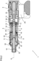
- FIG 1 shows a perspective view of a pulling and pushing device 1 with a drive unit 4 having an electric motor 3 and a gear 35 connected to the electric motor 3.
- a threaded spindle 7 of a screw drive 5 connected to the gear 35 is driven via the gear 35, wherein the threaded spindle 7 is rotatably mounted in a bearing receptacle 36 of a housing body 6 (cf. Figure 2 ).
- the screw drive 5 also has a threaded nut 9 arranged on the threaded spindle 7, which is mounted in a rotationally fixed manner on the housing body 6.
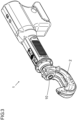
- the threaded nut 9 serves to drive a first tool holder designed as a piston rod 10, which is mounted in a bearing holder 33 in the longitudinal axis direction the threaded spindle 7, ie in the direction of the threaded spindle axis G, is adjustably mounted, so that by means of the pulling and pushing device 1 via a connected rivet bracket 2 (cf. Fig. 3 ) punch riveting operations can be carried out.
- the piston rod 10 is connected to the threaded nut 9 via a detachably connected coupling unit 11, which rests on a second end face 14 of the threaded nut 9 at its end opposite the piston rod 10.
- the coupling unit 11 also has projections 34 on its contact surface with the second end face 14 of the threaded nut 9, which projections engage in recesses on the second end face 14 of the threaded nut 9.
- a connecting element 12 is used to transmit the linear movement generated by the threaded nut 9 to the coupling unit 11.
- This has a first connecting section 15 which rests on the first end face 13 of the threaded nut 9 facing the gear 35 and a second connecting section 16 which is in engagement with a coupling section 20 of the coupling unit 11.
- the latter is arranged in the direction of the threaded spindle axis G so as to protrude beyond the second end face 14 of the threaded nut 9.
- the first and second connecting sections 15, 16 are connected to one another via a sleeve section 18, so that the connecting element 12 and the coupling unit 11 enclose the threaded nut 9 like a cage.
- Pressure movements i.e. adjustment movements of the threaded nut 9 in the direction of the piston rod 10 are transmitted to the coupling unit 11 via the direct contact of the coupling unit 11 with the second end face 14 of the threaded nut 9.
- the pressure forces acting on the first connecting section 15 resting on the first end face 13 of the threaded nut 9 are transmitted via the sleeve section 18 to the second connecting section 16, which is in engagement with the coupling section 20 of the coupling unit 11, so that the pressure forces are converted into tensile forces there.
- the coupling unit 11 has a bearing pin 19 which is aligned perpendicular to the threaded spindle axis G and protrudes from the coupling unit 11 and on which a bearing roller 21 is rotatably arranged.
- the bearing roller 21 is supported by two adjacent sections arranged to the threaded spindle axis G in the form of two parallel inner surfaces 24 of a guide designed as an elongated hole 22, so that when the threaded nut 9 is adjusted in the direction of the threaded spindle axis G, the bearing roller 21 rolls on the inner surfaces 24.
- the housing body 6 is formed in one piece from a metal material and the elongated hole 22 extends in the direction of the threaded spindle axis G.
- the bearing unit 8 and thus also the threaded nut 9 via the torsion-proof connection of the coupling unit 11 to the threaded nut 9 are supported on the housing body 6.
- the screw drive 5 is, as in Fig. 4 shown, designed to transmit rotary movements of the threaded spindle 7 to a second tool holder 25.
- a recess 26 is arranged on the threaded spindle 7 in order to form a positive connection in the circumferential direction of the threaded spindle axis G with a mold section 27 arranged on the second tool holder 25.
- the mold section 27 and the recess 26 each have a polygonal cross-section extending in the direction of the threaded spindle axis G.
- the coupling unit 11 is designed like a sleeve, ie the coupling unit 11 has a free area designed as a through opening 28 for the second tool holder 25 to pass through.
- a control unit 29 for controlling and/or archiving the operating processes is also arranged on the hand-held pulling and pushing device 1.
- the control unit 29 is connected to an actuating element 30 and a rotation sensor 31 for detecting the torque of the electric motor 3 and a force sensor 32 for detecting the pulling and pushing forces of the piston rod 10.
- the piston rod 10 is first released from the coupling unit 11 and removed from the housing base body 6 in the direction of the threaded spindle axis G.
- the second tool holder 25 is then pushed into the housing body 6 in the direction of the threaded spindle axis G, through the through hole 28 of the coupling unit 11 and the mold section 27 is connected to the recess 26 to form a positive connection with the threaded spindle 7.
Landscapes
- Engineering & Computer Science (AREA)
- Mechanical Engineering (AREA)
- Transmission Devices (AREA)
Claims (10)
- Dispositif manuel de traction et de compression pour l'entraînement d'outils interchangeables, comprenant- une unité d'entraînement (4), qui présente un moteur électrique (3) alimenté par batterie,- une commande filetée (5) avec une broche filetée (7) reliée au moteur électrique (3) et logée de manière rotative sur un corps de boîtier (6) et un écrou fileté (9) qui est logé de manière rotative sur la broche filetée (7) par l'intermédiaire d'une unité de palier (8) et de manière non rotative sur le corps de boîtier (6), et- une unité d'accouplement (11), qui est reliée à un premier logement d'outil (10), pour transmettre des forces de traction et de compression, qui résultent du sens de rotation de la broche filetée (7), de l'écrou fileté (9) au premier logement d'outil (10),caractérisé en ce que la commande de filetée (5) est conçue pour transmettre des mouvements de rotation de la broche filetée (7) à un deuxième logement d'outil (25) .
- Dispositif manuel de traction et de compression selon la revendication 1, caractérisé par un élément de raccordement (12) pour la transmission de forces de traction et de compression de l'écrou fileté (9) à l'unité d'accouplement (11), l'élément de raccordement (12) étant en liaison active avec une première face frontale (13) de l'écrou fileté (9) par l'intermédiaire d'un premier tronçon de liaison (15) et avec l'unité d'accouplement (11) par l'intermédiaire d'un deuxième tronçon de liaison (16).
- Dispositif manuel de traction et de compression selon la revendication 1 ou 2, caractérisé en ce que le premier tronçon de liaison (15) de l'élément de raccordement (12) s'applique contre la première face frontale (13) et le deuxième tronçon de liaison (16) est en prise avec un tronçon d'accouplement (20) de l'unité d'accouplement (11), en faisant saillie dans la direction de l'axe longitudinal de la broche filetée (7), au-delà d'une deuxième face frontale (14) de l'écrou fileté (9).
- Dispositif manuel de traction et de compression selon l'une des revendications précédentes, caractérisé en ce que l'unité d'accouplement (11) est conçue de telle sorte que le deuxième logement d'outil (25) peut être relié à la broche filetée (7).
- Dispositif manuel de traction et de compression selon l'une des revendications précédentes, caractérisé en ce que l'unité d'accouplement (11) est reliée à l'écrou fileté (9) de manière à résister à la torsion.
- Dispositif manuel de traction et de compression selon l'une des revendications précédentes, caractérisé en ce que l'unité de palier (8) est conçue de telle sorte que l'écrou fileté (9) et/ou l'unité d'accouplement (11) reliée à l'écrou fileté (9) de manière à résister à la torsion s'appuie en roulant sur le corps du boîtier (6) .
- Dispositif manuel de traction et de compression selon l'une des revendications précédentes, caractérisé en ce que le premier logement d'outil (10) est conçu pour être relié de manière amovible à l'unité d'accouplement (11) et/ou le deuxième logement d'outil (25) est conçu pour être relié de manière amovible à la broche filetée (7).
- Dispositif manuel de traction et de compression selon l'une des revendications précédentes, caractérisé en ce que la broche filetée (7) et/ou le deuxième logement d'outil (25) sont conçus pour former une liaison par complémentarité de forme dans la direction périphérique de la broche filetée (7).
- Dispositif manuel de traction et de compression selon l'une des revendications précédentes, caractérisé en ce que l'unité d'entraînement (4) comporte un engrenage (35) reliant le moteur électrique (3) et la broche filetée (7).
- Dispositif manuel de traction et de compression selon l'une des revendications précédentes, caractérisé par une unité de commande (29) reliée à au moins une unité de détection (31, 32) pour la commande et/ou l'archivage des opérations.
Priority Applications (3)
| Application Number | Priority Date | Filing Date | Title |
|---|---|---|---|
| EP23151823.4A EP4400229B1 (fr) | 2023-01-16 | 2023-01-16 | Dispositif de traction et d'impression portatif |
| CN202410040959.1A CN118341934A (zh) | 2023-01-16 | 2024-01-10 | 手持式拉压装置 |
| US18/412,371 US12343854B2 (en) | 2023-01-16 | 2024-01-12 | Hand-held pulling and compressing device |
Applications Claiming Priority (1)
| Application Number | Priority Date | Filing Date | Title |
|---|---|---|---|
| EP23151823.4A EP4400229B1 (fr) | 2023-01-16 | 2023-01-16 | Dispositif de traction et d'impression portatif |
Publications (3)
| Publication Number | Publication Date |
|---|---|
| EP4400229A1 EP4400229A1 (fr) | 2024-07-17 |
| EP4400229B1 true EP4400229B1 (fr) | 2024-12-11 |
| EP4400229C0 EP4400229C0 (fr) | 2024-12-11 |
Family
ID=84981464
Family Applications (1)
| Application Number | Title | Priority Date | Filing Date |
|---|---|---|---|
| EP23151823.4A Active EP4400229B1 (fr) | 2023-01-16 | 2023-01-16 | Dispositif de traction et d'impression portatif |
Country Status (3)
| Country | Link |
|---|---|
| US (1) | US12343854B2 (fr) |
| EP (1) | EP4400229B1 (fr) |
| CN (1) | CN118341934A (fr) |
Families Citing this family (2)
| Publication number | Priority date | Publication date | Assignee | Title |
|---|---|---|---|---|
| DE102021131294A1 (de) * | 2021-11-29 | 2023-06-01 | Tkr Spezialwerkzeuge Gmbh | Handhaltbare Zug- und Druckvorrichtung |
| DE102023116738B3 (de) * | 2023-06-26 | 2024-10-31 | Tkr Spezialwerkzeuge Gmbh | Handhaltbare Zug- und Druckvorrichtung |
Family Cites Families (21)
| Publication number | Priority date | Publication date | Assignee | Title |
|---|---|---|---|---|
| DE10216213A1 (de) * | 2002-04-10 | 2003-10-23 | Klauke Gmbh Gustav | Elektrohydraulisches Verpressgerät und Verfahren zum Betreiben desselben |
| KR950007694B1 (ko) * | 1988-03-28 | 1995-07-14 | 부라더 고교 가부시기가이샤 | 단축복합운동장치 |
| DE10251387B4 (de) * | 2002-11-01 | 2006-04-27 | Ralf Kosan | Elektrische Preßvorrichtung |
| EP1658907A1 (fr) * | 2004-11-17 | 2006-05-24 | Dino Sodini | Outil pour la correction des carrosseries abîmées |
| US7533556B2 (en) * | 2006-03-15 | 2009-05-19 | Fci Americas Technology, Inc. | Hydraulic tool release system |
| WO2009049367A1 (fr) * | 2007-10-19 | 2009-04-23 | Whitehot Solutions Pty Ltd | Outil manuel à multiples mandrins de serrage |
| CN201619097U (zh) * | 2010-01-11 | 2010-11-03 | 付俊杰 | 一种多功能电动工具 |
| WO2012164590A1 (fr) * | 2011-06-01 | 2012-12-06 | Cembre S.P.A. | Outil hydrodynamique, pompe hydraulique, et mécanisme pour transformer un mouvement rotatif en un mouvement de translation oscillant pour un tel outil |
| DE202012012292U1 (de) * | 2012-12-28 | 2014-04-04 | Kmt Produktions + Montagetechnik Gmbh | Taumel- oder Radialpunktnietmaschine |
| CN203430470U (zh) * | 2013-08-20 | 2014-02-12 | 长春市斯普瑞新技术有限责任公司 | 一种电动密封段 |
| WO2015083268A1 (fr) * | 2013-12-05 | 2015-06-11 | 株式会社小林工具製作所 | Dispositif à mouvement alternatif rectiligne utilisant une perceuse électrique |
| US9701032B2 (en) * | 2014-07-23 | 2017-07-11 | Black & Decker Inc. | Power tool accessory with brace |
| CN104308790B (zh) * | 2014-09-29 | 2015-08-26 | 洪劲松 | 铆螺母电动工具 |
| US10312653B2 (en) * | 2015-05-06 | 2019-06-04 | Milwaukee Electric Tool Corporation | Hydraulic tool |
| US10471578B2 (en) * | 2016-03-02 | 2019-11-12 | Cembre S.P.A. | Hydrodynamic compression or cutting tool |
| EP3680067B1 (fr) * | 2017-12-07 | 2021-10-06 | Maxell Izumi Co., Ltd. | Outil électrique |
| US11292118B2 (en) * | 2018-01-30 | 2022-04-05 | Milwaukee Electric Tool Corporation | Power tool |
| US11878402B2 (en) * | 2019-03-18 | 2024-01-23 | Milwaukee Electric Tool Corporation | Hydraulic power tool |
| JP7490467B2 (ja) * | 2020-06-23 | 2024-05-27 | 株式会社マキタ | 締結工具 |
| JP7745490B2 (ja) * | 2022-03-22 | 2025-09-29 | マクセルイズミ株式会社 | 電動工具 |
| TWI820886B (zh) * | 2022-08-31 | 2023-11-01 | 科頡工業股份有限公司 | 活塞泵自動回油結構 |
-
2023
- 2023-01-16 EP EP23151823.4A patent/EP4400229B1/fr active Active
-
2024
- 2024-01-10 CN CN202410040959.1A patent/CN118341934A/zh active Pending
- 2024-01-12 US US18/412,371 patent/US12343854B2/en active Active
Also Published As
| Publication number | Publication date |
|---|---|
| US20240238960A1 (en) | 2024-07-18 |
| US12343854B2 (en) | 2025-07-01 |
| CN118341934A (zh) | 2024-07-16 |
| EP4400229A1 (fr) | 2024-07-17 |
| EP4400229C0 (fr) | 2024-12-11 |
Similar Documents
| Publication | Publication Date | Title |
|---|---|---|
| EP4440776A1 (fr) | Dispositif portatif de traction et de compression | |
| DE102009054930B4 (de) | Bohrmaschine | |
| EP4400229B1 (fr) | Dispositif de traction et d'impression portatif | |
| DE102009054925B4 (de) | Bohrmaschine | |
| EP2871027B1 (fr) | Outil de serrage de boulon | |
| EP3957441B1 (fr) | Dispositif de pose fixateur de rivets aveugles | |
| EP3700799A1 (fr) | Colonne de direction pour véhicule automobile | |
| DE102013221697B4 (de) | Handwerkzeugmaschine mit einer Drehmomentkupplung | |
| WO2022111998A1 (fr) | Engrenage excentrique pour machine-outil | |
| EP4484062A1 (fr) | Dispositif de traction et d'impression portatif et système modulaire | |
| EP3208164A1 (fr) | Vis d'entrainement a bille | |
| EP4547425A1 (fr) | Appareil de rivetage à structure compacte | |
| EP0840021A1 (fr) | Dispositif pour la connexion d'éléments de montage | |
| DE102023116738B3 (de) | Handhaltbare Zug- und Druckvorrichtung | |
| DE102023116741B3 (de) | Handhaltbare Zug- und Druckvorrichtung sowie mechanischer Kraftverstärker | |
| EP0275331A1 (fr) | Mandrin expansible | |
| EP2216555B1 (fr) | Dispositif de serrage | |
| EP4484061B1 (fr) | Dispositif de traction et d'impression portatif | |
| EP1566238B1 (fr) | Système électrique de mouvement linéaire avec un accouplement direct entre un système vis-écrou et un module moteur | |
| DE102016103197A1 (de) | Riemengetriebe und lenksystem | |
| EP4547423A1 (fr) | Dispositif de rivetage, contenant de mandrin et procédé d'assemblage d'un dispositif de rivetage | |
| EP3943226A1 (fr) | Machine de perçage | |
| EP1260322B1 (fr) | Clef motorisée à tête angulaire | |
| EP2949427A1 (fr) | Outil destiné à fixer un connecteur à vis sur un câble électrique | |
| DE102019213452A1 (de) | Verfahren zur Einstellung der Riemenspannung einer elektromechanischen Fahrzeuglenkung, elektromechanische Fahrzeuglenkung und Einstellstift |
Legal Events
| Date | Code | Title | Description |
|---|---|---|---|
| PUAI | Public reference made under article 153(3) epc to a published international application that has entered the european phase |
Free format text: ORIGINAL CODE: 0009012 |
|
| STAA | Information on the status of an ep patent application or granted ep patent |
Free format text: STATUS: THE APPLICATION HAS BEEN PUBLISHED |
|
| AK | Designated contracting states |
Kind code of ref document: A1 Designated state(s): AL AT BE BG CH CY CZ DE DK EE ES FI FR GB GR HR HU IE IS IT LI LT LU LV MC ME MK MT NL NO PL PT RO RS SE SI SK SM TR |
|
| STAA | Information on the status of an ep patent application or granted ep patent |
Free format text: STATUS: REQUEST FOR EXAMINATION WAS MADE |
|
| 17P | Request for examination filed |
Effective date: 20240801 |
|
| RBV | Designated contracting states (corrected) |
Designated state(s): AL AT BE BG CH CY CZ DE DK EE ES FI FR GB GR HR HU IE IS IT LI LT LU LV MC ME MK MT NL NO PL PT RO RS SE SI SK SM TR |
|
| GRAP | Despatch of communication of intention to grant a patent |
Free format text: ORIGINAL CODE: EPIDOSNIGR1 |
|
| STAA | Information on the status of an ep patent application or granted ep patent |
Free format text: STATUS: GRANT OF PATENT IS INTENDED |
|
| GRAS | Grant fee paid |
Free format text: ORIGINAL CODE: EPIDOSNIGR3 |
|
| GRAA | (expected) grant |
Free format text: ORIGINAL CODE: 0009210 |
|
| STAA | Information on the status of an ep patent application or granted ep patent |
Free format text: STATUS: THE PATENT HAS BEEN GRANTED |
|
| INTG | Intention to grant announced |
Effective date: 20241023 |
|
| AK | Designated contracting states |
Kind code of ref document: B1 Designated state(s): AL AT BE BG CH CY CZ DE DK EE ES FI FR GB GR HR HU IE IS IT LI LT LU LV MC ME MK MT NL NO PL PT RO RS SE SI SK SM TR |
|
| REG | Reference to a national code |
Ref country code: GB Ref legal event code: FG4D Free format text: NOT ENGLISH |
|
| REG | Reference to a national code |
Ref country code: CH Ref legal event code: EP |
|
| REG | Reference to a national code |
Ref country code: DE Ref legal event code: R096 Ref document number: 502023000371 Country of ref document: DE |
|
| REG | Reference to a national code |
Ref country code: IE Ref legal event code: FG4D Free format text: LANGUAGE OF EP DOCUMENT: GERMAN |
|
| U01 | Request for unitary effect filed |
Effective date: 20241211 |
|
| U07 | Unitary effect registered |
Designated state(s): AT BE BG DE DK EE FI FR IT LT LU LV MT NL PT RO SE SI Effective date: 20241220 |
|
| U20 | Renewal fee for the european patent with unitary effect paid |
Year of fee payment: 3 Effective date: 20250220 |
|
| PG25 | Lapsed in a contracting state [announced via postgrant information from national office to epo] |
Ref country code: HR Free format text: LAPSE BECAUSE OF FAILURE TO SUBMIT A TRANSLATION OF THE DESCRIPTION OR TO PAY THE FEE WITHIN THE PRESCRIBED TIME-LIMIT Effective date: 20241211 |
|
| PG25 | Lapsed in a contracting state [announced via postgrant information from national office to epo] |
Ref country code: ES Free format text: LAPSE BECAUSE OF FAILURE TO SUBMIT A TRANSLATION OF THE DESCRIPTION OR TO PAY THE FEE WITHIN THE PRESCRIBED TIME-LIMIT Effective date: 20241211 |
|
| PG25 | Lapsed in a contracting state [announced via postgrant information from national office to epo] |
Ref country code: NO Free format text: LAPSE BECAUSE OF FAILURE TO SUBMIT A TRANSLATION OF THE DESCRIPTION OR TO PAY THE FEE WITHIN THE PRESCRIBED TIME-LIMIT Effective date: 20250311 |
|
| PG25 | Lapsed in a contracting state [announced via postgrant information from national office to epo] |
Ref country code: GR Free format text: LAPSE BECAUSE OF FAILURE TO SUBMIT A TRANSLATION OF THE DESCRIPTION OR TO PAY THE FEE WITHIN THE PRESCRIBED TIME-LIMIT Effective date: 20250312 |
|
| PG25 | Lapsed in a contracting state [announced via postgrant information from national office to epo] |
Ref country code: RS Free format text: LAPSE BECAUSE OF FAILURE TO SUBMIT A TRANSLATION OF THE DESCRIPTION OR TO PAY THE FEE WITHIN THE PRESCRIBED TIME-LIMIT Effective date: 20250311 |
|
| PG25 | Lapsed in a contracting state [announced via postgrant information from national office to epo] |
Ref country code: SM Free format text: LAPSE BECAUSE OF FAILURE TO SUBMIT A TRANSLATION OF THE DESCRIPTION OR TO PAY THE FEE WITHIN THE PRESCRIBED TIME-LIMIT Effective date: 20241211 |
|
| PG25 | Lapsed in a contracting state [announced via postgrant information from national office to epo] |
Ref country code: PL Free format text: LAPSE BECAUSE OF FAILURE TO SUBMIT A TRANSLATION OF THE DESCRIPTION OR TO PAY THE FEE WITHIN THE PRESCRIBED TIME-LIMIT Effective date: 20241211 |
|
| PG25 | Lapsed in a contracting state [announced via postgrant information from national office to epo] |
Ref country code: IS Free format text: LAPSE BECAUSE OF FAILURE TO SUBMIT A TRANSLATION OF THE DESCRIPTION OR TO PAY THE FEE WITHIN THE PRESCRIBED TIME-LIMIT Effective date: 20250411 |
|
| PG25 | Lapsed in a contracting state [announced via postgrant information from national office to epo] |
Ref country code: SK Free format text: LAPSE BECAUSE OF FAILURE TO SUBMIT A TRANSLATION OF THE DESCRIPTION OR TO PAY THE FEE WITHIN THE PRESCRIBED TIME-LIMIT Effective date: 20241211 |
|
| PG25 | Lapsed in a contracting state [announced via postgrant information from national office to epo] |
Ref country code: CZ Free format text: LAPSE BECAUSE OF FAILURE TO SUBMIT A TRANSLATION OF THE DESCRIPTION OR TO PAY THE FEE WITHIN THE PRESCRIBED TIME-LIMIT Effective date: 20241211 |
|
| PG25 | Lapsed in a contracting state [announced via postgrant information from national office to epo] |
Ref country code: MC Free format text: LAPSE BECAUSE OF FAILURE TO SUBMIT A TRANSLATION OF THE DESCRIPTION OR TO PAY THE FEE WITHIN THE PRESCRIBED TIME-LIMIT Effective date: 20241211 |
|
| PLBE | No opposition filed within time limit |
Free format text: ORIGINAL CODE: 0009261 |
|
| STAA | Information on the status of an ep patent application or granted ep patent |
Free format text: STATUS: NO OPPOSITION FILED WITHIN TIME LIMIT |
|
| 26N | No opposition filed |
Effective date: 20250912 |
|
| PG25 | Lapsed in a contracting state [announced via postgrant information from national office to epo] |
Ref country code: IE Free format text: LAPSE BECAUSE OF NON-PAYMENT OF DUE FEES Effective date: 20250116 |
|
| U20 | Renewal fee for the european patent with unitary effect paid |
Year of fee payment: 4 Effective date: 20260128 |