EP4484062A1 - Dispositif de traction et d'impression portatif et système modulaire - Google Patents
Dispositif de traction et d'impression portatif et système modulaire Download PDFInfo
- Publication number
- EP4484062A1 EP4484062A1 EP24178554.2A EP24178554A EP4484062A1 EP 4484062 A1 EP4484062 A1 EP 4484062A1 EP 24178554 A EP24178554 A EP 24178554A EP 4484062 A1 EP4484062 A1 EP 4484062A1
- Authority
- EP
- European Patent Office
- Prior art keywords
- unit
- coupling
- tool
- threaded spindle
- drive unit
- Prior art date
- Legal status (The legal status is an assumption and is not a legal conclusion. Google has not performed a legal analysis and makes no representation as to the accuracy of the status listed.)
- Pending
Links
Images


Classifications
-
- B—PERFORMING OPERATIONS; TRANSPORTING
- B25—HAND TOOLS; PORTABLE POWER-DRIVEN TOOLS; MANIPULATORS
- B25B—TOOLS OR BENCH DEVICES NOT OTHERWISE PROVIDED FOR, FOR FASTENING, CONNECTING, DISENGAGING, OR HOLDING
- B25B27/00—Hand tools, specially adapted for fitting together or separating parts or objects whether or not involving some deformation, not otherwise provided for
- B25B27/0007—Tools for fixing internally screw-threaded tubular fasteners
- B25B27/0014—Tools for fixing internally screw-threaded tubular fasteners motor-driven
-
- B—PERFORMING OPERATIONS; TRANSPORTING
- B25—HAND TOOLS; PORTABLE POWER-DRIVEN TOOLS; MANIPULATORS
- B25B—TOOLS OR BENCH DEVICES NOT OTHERWISE PROVIDED FOR, FOR FASTENING, CONNECTING, DISENGAGING, OR HOLDING
- B25B21/00—Portable power-driven screw or nut setting or loosening tools; Attachments for drilling apparatus serving the same purpose
-
- B—PERFORMING OPERATIONS; TRANSPORTING
- B21—MECHANICAL METAL-WORKING WITHOUT ESSENTIALLY REMOVING MATERIAL; PUNCHING METAL
- B21J—FORGING; HAMMERING; PRESSING METAL; RIVETING; FORGE FURNACES
- B21J15/00—Riveting
- B21J15/10—Riveting machines
- B21J15/105—Portable riveters
-
- B—PERFORMING OPERATIONS; TRANSPORTING
- B21—MECHANICAL METAL-WORKING WITHOUT ESSENTIALLY REMOVING MATERIAL; PUNCHING METAL
- B21J—FORGING; HAMMERING; PRESSING METAL; RIVETING; FORGE FURNACES
- B21J15/00—Riveting
- B21J15/10—Riveting machines
- B21J15/16—Drives for riveting machines; Transmission means therefor
- B21J15/26—Drives for riveting machines; Transmission means therefor operated by rotary drive, e.g. by electric motor
-
- B—PERFORMING OPERATIONS; TRANSPORTING
- B21—MECHANICAL METAL-WORKING WITHOUT ESSENTIALLY REMOVING MATERIAL; PUNCHING METAL
- B21J—FORGING; HAMMERING; PRESSING METAL; RIVETING; FORGE FURNACES
- B21J15/00—Riveting
- B21J15/10—Riveting machines
- B21J15/28—Control devices specially adapted to riveting machines not restricted to one of the preceding subgroups
-
- B—PERFORMING OPERATIONS; TRANSPORTING
- B25—HAND TOOLS; PORTABLE POWER-DRIVEN TOOLS; MANIPULATORS
- B25B—TOOLS OR BENCH DEVICES NOT OTHERWISE PROVIDED FOR, FOR FASTENING, CONNECTING, DISENGAGING, OR HOLDING
- B25B27/00—Hand tools, specially adapted for fitting together or separating parts or objects whether or not involving some deformation, not otherwise provided for
- B25B27/02—Hand tools, specially adapted for fitting together or separating parts or objects whether or not involving some deformation, not otherwise provided for for connecting objects by press fit or detaching same
- B25B27/10—Hand tools, specially adapted for fitting together or separating parts or objects whether or not involving some deformation, not otherwise provided for for connecting objects by press fit or detaching same inserting fittings into hoses
-
- B—PERFORMING OPERATIONS; TRANSPORTING
- B25—HAND TOOLS; PORTABLE POWER-DRIVEN TOOLS; MANIPULATORS
- B25F—COMBINATION OR MULTI-PURPOSE TOOLS NOT OTHERWISE PROVIDED FOR; DETAILS OR COMPONENTS OF PORTABLE POWER-DRIVEN TOOLS NOT PARTICULARLY RELATED TO THE OPERATIONS PERFORMED AND NOT OTHERWISE PROVIDED FOR
- B25F3/00—Associations of tools for different working operations with one portable power-drive means; Adapters therefor
-
- F—MECHANICAL ENGINEERING; LIGHTING; HEATING; WEAPONS; BLASTING
- F16—ENGINEERING ELEMENTS AND UNITS; GENERAL MEASURES FOR PRODUCING AND MAINTAINING EFFECTIVE FUNCTIONING OF MACHINES OR INSTALLATIONS; THERMAL INSULATION IN GENERAL
- F16H—GEARING
- F16H25/00—Gearings comprising primarily only cams, cam-followers and screw-and-nut mechanisms
- F16H25/18—Gearings comprising primarily only cams, cam-followers and screw-and-nut mechanisms for conveying or interconverting oscillating or reciprocating motions
- F16H25/20—Screw mechanisms
-
- F—MECHANICAL ENGINEERING; LIGHTING; HEATING; WEAPONS; BLASTING
- F16—ENGINEERING ELEMENTS AND UNITS; GENERAL MEASURES FOR PRODUCING AND MAINTAINING EFFECTIVE FUNCTIONING OF MACHINES OR INSTALLATIONS; THERMAL INSULATION IN GENERAL
- F16H—GEARING
- F16H25/00—Gearings comprising primarily only cams, cam-followers and screw-and-nut mechanisms
- F16H25/18—Gearings comprising primarily only cams, cam-followers and screw-and-nut mechanisms for conveying or interconverting oscillating or reciprocating motions
- F16H25/20—Screw mechanisms
- F16H2025/2062—Arrangements for driving the actuator
- F16H2025/2075—Coaxial drive motors
Definitions
- the invention relates to a hand-held pulling and pushing device for driving interchangeable tools.
- Hand-held pulling and pushing devices i.e. devices that can be used by a person in a mobile manner, such as hand-held, electric riveting and pressing devices for setting blind rivet elements, such as blind rivets and blind rivet nuts, or for carrying out punching processes and for setting punch rivets, which have a drive unit with an electric motor-driven threaded spindle of a screw drive, are known in a variety of designs from the prior art.
- the screw drive converts a rotary movement of the electric motor into a linear movement of the pulling or pressing tool in a known manner.
- a pulling mandrel of the blind rivet element is moved axially.
- the hand-held pulling and pushing devices described above are used, for example, in motor vehicle workshops when carrying out repair work on the bodywork of vehicles and when maintaining pipe or cable connections. Depending on the work to be carried out, it is necessary to use a large number of different interchangeable tools with the pulling and pushing devices, for example with different levels of force.
- the invention is based on the object of providing a hand-held pull and printing device that can be used easily and flexibly for different work processes.
- the invention solves the problem by a hand-held pulling and pushing device with the features of claim 1 and by a modular system with the features of claim 8.
- Advantageous further developments of the hand-held pulling and pushing device are specified in claims 2 to 7.
- the hand-held pulling and pushing device has a tool unit with a screw drive and a tool holder.
- the screw drive has a threaded spindle that is rotatably mounted on a housing body and a threaded nut that is rotatably mounted on the threaded spindle and non-rotatably mounted on the housing body via a bearing unit.
- the pulling and pushing device has a drive unit that can be connected to the tool unit via a coupling and has a battery-operated electric motor for driving the threaded spindle.
- the tool unit is connected via a coupling unit to a tool holder which is designed to interchangeably hold different tools required for the respective application, for example drawing and pressing tools and/or rotary tools.
- the tool holder can be designed, for example, to hold a rivet striker, which is used in conjunction with a rivet bracket arranged on the pressure device to set rivets.
- the tool holder can, for example, be provided with suitable clamping devices for a blind rivet shaft or have other means for transmitting tensile forces.
- the tool holder can also be designed to hold corresponding pulling tools, whereby the pulling tools have, for example, clamping means by means of which the tensile forces can then be transmitted.
- the coupling unit is connected to the threaded nut in such a way that both tensile and compressive forces, which arise from the direction of movement of the threaded spindle and the resulting linear adjustment of the threaded nut are reliably transferred to the coupling unit.
- the electric motor and the battery for operating the electric motor are preferably arranged in a base body that can be connected to the housing body of the tool unit via the coupling.
- the coupling is particularly preferably designed in such a way that the torque generated by the drive unit is transmitted to the screw drive when the drive unit is attached to the tool unit.
- the pulling and pushing device allows tool units of different designs to be connected to the drive unit depending on the work to be carried out, for example when used in a motor vehicle workshop when carrying out bodywork work.
- the coupling provided according to the invention allows a simple and standardized connection of the various tool units optimized for the different work to the drive unit and, in the event of maintenance, a simple and quick replacement of the tool unit and/or the drive unit.
- the pulling and pushing device formed by connecting the drive unit to a tool unit allows either pulling or pressing work to be carried out, for example setting blind rivets or carrying out punching work.
- the linear adjustment of the selected tool required for the respective work step is reliably transmitted to the tool holder via the coupling unit, after the coupling unit transmits both pulling and pushing forces from the threaded nut via the tool holder to the respective tool.
- the coupling has a data line and a power supply.
- the data line enables the transmission of data between the drive unit and the tool unit. For example, measured values recorded by the tool unit are transmitted to the drive unit as data, or information for various operations, such as travel paths of the screw drive or the tool holder, is transmitted from the drive unit to the tool unit.
- the power supply also provides ensure that the tool unit is supplied with power by the drive unit. For example, the power supply enables a tool with a magnetic lock to be arranged on the tool unit and operated with it.
- the tool unit can be attached to the base body of the drive unit in any way.
- a connection section arranged on the housing body of the tool unit which is designed as a thread, for example, which makes it possible to attach the tool unit with corresponding threads to a connection section of the base body of the drive unit.
- the coupling for connecting the drive unit to the tool unit is designed as an electrical and/or mechanical coupling.
- the coupling is designed as a mechanical bayonet lock or as a ball lock. Regardless of whether it is designed as an electrical or mechanical coupling, the coupling is preferably adjustable between a locking position and an unlocking position.
- the tool unit and the drive unit are preferably connected to one another in such a way that the torque generated by the drive unit is transmitted to the tool unit, for example the threaded spindle of the screw drive.
- the tool unit and the drive unit can be separated from one another, so that the tool unit or the drive unit can be replaced easily and flexibly if necessary.
- the coupling is preferably designed as a quick coupling.
- the use of a quick coupling which is characterized in that it can be quickly adjusted by the operator with little effort between the unlocking position, in which the tool unit can be arranged on the drive unit or removed from it, and the locking position, in which the tool unit is fixed to the drive unit.
- the quick coupling is characterized in particular by the fact that additional tools for removing or arranging the tool unit can be dispensed with.
- a design of the hand-held pull and push device with a quick coupling thus enables a quick and convenient change or assembly and disassembly of a tool unit. to or from the pulling and pushing device.
- the quick coupling can be adjusted between the unlocking and locking positions in any way, for example the quick coupling can be designed in such a way that it can be adjusted mechanically by an operator between the unlocking and locking positions.
- the quick coupling is particularly preferably adjustable between the unlocking and locking positions using the drive unit. Using the drive unit to operate the quick coupling, i.e. to adjust it between the unlocking and locking positions, increases the comfort of the hand-held pull and push device in a special way. Incorrect operation of the quick couplings is also minimized or completely avoided by operating it using the drive unit.
- the tool unit has a switching unit that can be adjusted between a coupling position that connects the threaded spindle, in particular when the coupling is arranged in the locking position, to the drive unit and a decoupling position that separates the threaded spindle from the drive unit.
- the threaded drive In the coupling position, the threaded drive is preferably connected to the drive unit via the switching unit in such a way that rotary movements of the electric motor are transmitted to the threaded spindle.
- the threaded drive is preferably separated from the drive unit by the switching unit in such a way that the rotary movement of the electric motor is not transmitted to the threaded spindle.
- the switching unit is adjusted between the positions, for example, manually, for example by a user, or automatically, for example by a control unit.
- the switching unit enables the screw drive to be easily decoupled from the drive unit even when the clutch is in the locking position, whereby the rotary movement of the electric motor is not transmitted to the threaded spindle and thus the linear adjustment of the threaded nut and/or the coupling unit and/or the tool holder is blocked.
- the threaded spindle and/or the switching unit and/or the rotary shaft is designed for a positive connection to a drive shaft of the drive unit.
- the rotary shaft and the switching unit preferably have at least one coupling section for a positive connection to the drive shaft.
- the threaded spindle can preferably be connected to the drive shaft indirectly via the switching unit.
- the rotary shaft preferably has at least one first coupling section, which can particularly preferably be brought into engagement with a coupling section arranged on the drive shaft.
- the first coupling section and/or the coupling section are preferably designed such that in the locking position a positive connection is created between the rotary shaft and the drive unit in the circumferential direction of the longitudinal axis of the drive shaft.
- the switching unit is preferably connected to the drive shaft of the drive unit in a positive-locking manner, for example via a second coupling section designed as a key or a key-like connection.
- the coupling section is preferably arranged on an end section of the drive shaft.
- the end section of the drive shaft describes a section extending from an end face of the drive shaft in the direction of the longitudinal axis of the drive shaft.
- the first coupling section is preferably designed as a projection protruding from an end face of the rotary shaft facing the drive unit and the coupling section is designed as a recess in the end face of the drive shaft.
- the coupling sections advantageously provided on the rotary shaft and/or the switching unit as well as the coupling section preferably provided on the drive shaft enable the rotary shaft and/or the switching unit and/or the screw drive to be fixed to the drive unit in a simple manner and, due to the positive connection in the circumferential direction of the drive shaft, a particularly reliable transmission of the rotary movement of the drive unit to the tool unit.
- the screw drive of the tool unit is designed such that a rotary shaft for transmitting rotary movements of the electric motor to a Tool can be arranged on the electric motor.
- the threaded spindle is designed as a hollow spindle for receiving a rotary shaft that can be connected to the drive unit.
- a hollow spindle is understood to mean a threaded spindle with a hollow space extending in the longitudinal axis direction of the threaded spindle.
- the rotary shaft can preferably be connected to the electric motor in such a way that the rotary shaft can be rotated independently of the switching unit arranged in the coupling position or in the decoupling position.
- the rotary shaft is preferably arranged coaxially to the hollow spindle.
- the rotary shaft is particularly preferably mounted in the hollow spindle so that it can rotate about the longitudinal axis of the hollow spindle.
- at least one bearing element e.g. a roller bearing, for example a needle roller bearing or a ball bearing, is provided for supporting the rotary shaft.
- the tool holder is particularly preferably also designed to be hollow in order to enable a rotary tool to be connected to the rotary shaft without first removing the tool holder connected to the coupling unit.
- the design of the threaded spindle as a hollow spindle makes it easy to arrange the rotary shaft on the drive unit so that the rotary shaft can rotate independently of the position of the switching unit. This enables easy switching between the transmission of tensile and/or compressive forces via the tool holder and the transmission of rotary movements via the rotary shaft. Furthermore, there is no need for an additional tool holder connected to the threaded spindle to replace the tool holder connected to the coupling unit.
- the rotary movement transmitted from the rotary shaft to a tool is not limited by the stroke of the threaded nut and/or the tool holder, so that the hand-held pulling and pushing device can be used particularly flexibly.
- the transmission of the torque of the drive unit to the tool unit, in particular the switching unit and/or the threaded spindle and/or the rotary shaft can in principle be carried out in any manner.
- the drive unit has a gear connected to the electric motor, which has the drive shaft that can be connected to the tool unit.
- the use of a gearbox allows high torques to be transmitted in a small space and weight.
- gears For example, two- to three-stage planetary gears, but also cycloidal and spur gears are used as gears, which offer the desired gear ratios.
- the speed of the electric motor is preferably 25,000 - 30,000 rpm, preferably 26,000 - 29,000 rpm, particularly preferably 27,000-28,000 rpm, very particularly preferably 27,500 rpm.
- brushless motors which are battery-operated, an optimal coordination between the gear, threaded spindle and the resulting force can be achieved.
- the drive unit in particular the electric motor and/or the gear, are designed in such a way that a torque of 10-100 Nm, preferably 15-95 Nm, very particularly preferably 15-25 Nm and/or 75-95 Nm can be transmitted to the tool unit, in particular the threaded spindle and/or the rotary shaft.
- the electric motor can be operated in such a way that only the direction of rotation of the drive shaft can be selected.
- the drive unit particularly preferably has a control unit connected to at least one sensor unit for controlling and/or archiving the operating processes.
- control unit allows a targeted control of the corresponding operating processes, for example pulling, pressing and/or turning processes and, for example, the adjustment of the coupling between the unlocking position and the locking position.
- control unit can be used to set the respective tensile or compressive forces in a particularly simple manner, so that the operating processes can be carried out particularly reliably.
- control unit can be used to automatically adjust the switching unit and the coupling, in particular the quick coupling. This enables a particularly simple and flexible assembly and disassembly of the tool unit from the drive unit and, on the other hand, the programming of more complex processes in which different operations, for example using tensile and compressive forces or torques, can be carried out one after the other or in any combination.
- a blind rivet nut is first tightened by the The torque transmitted by the rotary shaft is screwed into the thread provided for this purpose and then, after the switching unit is switched from the uncoupling position to the coupling position, it is set by the tensile forces generated by the screw drive and transmitted to the tool holder via the coupling unit.
- the control unit can also be designed to archive the operating processes carried out so that the work carried out can be reliably recorded.
- the sensor unit can be designed to monitor the adjustment path, the pulling or pressing forces, the torque or the like, which is required for carrying out the work processes and their successful completion. Furthermore, the sensor unit can, for example, monitor the coupling and, in the event of a faulty connection between the tool unit and the drive unit, display a warning or error message on a preferably provided display.
- the display also makes it particularly easy for the operating personnel to operate the hand-held pulling and pushing device. This can also be connected to a central database or a mobile handheld device, for example a smartphone or tablet, via suitable wireless transmission means.
- the invention further solves the problem by a modular system for a hand-held pulling and pushing device according to the invention or further developed as described above, with at least two tool units designed to generate different pulling and pushing forces and at least one drive unit that can be connected to the tool units.
- the tool units differ primarily in their design, which is optimized for specific work processes, particularly in terms of the weight, dimensions or ergonomics of the tool unit.
- the threaded spindles of the tool units have different pitches or the tool units are integrally connected to different tools, which makes it impossible to change the tools.
- the system according to the invention makes it possible to use the hand-held pulling and pushing device for a variety of different work processes and to operate different tool units with one drive unit.
- This provides a continuously expandable system for the hand-held pulling and pushing device, in which the drive unit is used sustainably and yet different fields of work are possible.
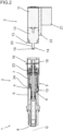
- Figure 1 shows in a perspective view a pulling and pushing device 1 with a tool unit 2 and a drive unit 3 separate from this.
- the screw drive 5 has a threaded nut 7 arranged on the threaded spindle 4, which is mounted in a rotationally fixed manner on the housing body 6.
- the threaded nut 7 serves to drive a tool holder designed as a piston rod 8, which is adjustably mounted in the longitudinal axis direction of the threaded spindle 4, ie in the direction of the threaded spindle axis G.
- the piston rod 8 is connected to the threaded nut 7 via a detachably connected coupling unit 9.
- the drive unit 3 has an electric motor 11 and a gear 12 connected to the electric motor 11 with a drive shaft 14.
- the drive unit 3 can be connected to the tool unit 2 via a coupling 13.
- the coupling 13 is arranged between a Fig. 1 and 2 unlocking position shown and one in Figure 3 shown locking position. Furthermore, the coupling has a data line for transmitting signals between the tool unit 2 and a control unit 22 of the drive unit 3 as well as a power supply for the tool unit 2.
- the tool unit 2 also has a switching unit 16 for coupling and decoupling the screw drive 5 from the drive unit 3.
- the switching unit 13 is arranged between a Fig. 3 exemplary coupling position and a decoupling position separating the threaded spindle 4 from the drive unit 3.
- the threaded spindle is designed as a hollow spindle 4 for receiving a rotary shaft 17 connected to the electric motor 3.
- the rotary shaft 17 can be connected to the drive unit 3 in such a way that the rotary shaft 17 can be rotated independently of the switching unit 16 arranged in the coupling position or in the decoupling position.
- the rotary shaft 17 is arranged coaxially to the hollow spindle 6.
- the rotary shaft 17 has a first coupling section 18 which can be brought into engagement with a coupling section 19 arranged on the drive shaft 14.
- the first coupling section 18 and the coupling section 19 are designed in such a way that in the locking position of the coupling a positive connection is created between the rotary shaft 17 and the drive unit 3 in the circumferential direction of the longitudinal axis of the threaded spindle axis G.
- the switching unit 16 is positively connected via a
- the second coupling section 20, which is formed with a key, is connected to the drive shaft 14 of the drive unit 3 (cf. Fig.3 ).
- the drive unit 3 also has a battery 21 for operating the electric motor 11 and the control unit 22 for controlling and/or archiving the operating processes.
- the control unit 22 is connected to a rotation sensor 23 for detecting the torque of the drive unit 3 and a force sensor 24 for detecting the tensile and compressive forces of the tool unit 2.
- the control unit 22 is also connected to a contact sensor 25 for checking the connection of the tool unit 2 to the drive unit 3 via the coupling 13.
- the electric motor 11, the battery 21 and the control unit 22 are arranged in a base body (not shown) that can be connected to the housing body 6 of the tool unit 2 via the coupling 13.
- a system (not shown) for the hand-held pulling and pushing device 1 has at least two tool units 2 designed to generate different pulling and pushing forces and at least one drive unit 3 that can be connected to the tool units 2.
- the coupling 13 for connecting the drive unit 3 to the tool unit 2 is designed as an electrical quick coupling, which can be electrically adjusted between the locking position and the unlocking position via the control unit 22.
Landscapes
- Engineering & Computer Science (AREA)
- Mechanical Engineering (AREA)
- General Engineering & Computer Science (AREA)
- Details Of Spanners, Wrenches, And Screw Drivers And Accessories (AREA)
Applications Claiming Priority (1)
| Application Number | Priority Date | Filing Date | Title |
|---|---|---|---|
| DE102023116744.8A DE102023116744B3 (de) | 2023-06-26 | 2023-06-26 | Handhaltbare Zug- und Druckvorrichtung sowie modulares System |
Publications (1)
| Publication Number | Publication Date |
|---|---|
| EP4484062A1 true EP4484062A1 (fr) | 2025-01-01 |
Family
ID=93015220
Family Applications (1)
| Application Number | Title | Priority Date | Filing Date |
|---|---|---|---|
| EP24178554.2A Pending EP4484062A1 (fr) | 2023-06-26 | 2024-05-28 | Dispositif de traction et d'impression portatif et système modulaire |
Country Status (4)
| Country | Link |
|---|---|
| US (1) | US20240424647A1 (fr) |
| EP (1) | EP4484062A1 (fr) |
| CN (1) | CN119187429A (fr) |
| DE (1) | DE102023116744B3 (fr) |
Families Citing this family (2)
| Publication number | Priority date | Publication date | Assignee | Title |
|---|---|---|---|---|
| DE102021131294A1 (de) * | 2021-11-29 | 2023-06-01 | Tkr Spezialwerkzeuge Gmbh | Handhaltbare Zug- und Druckvorrichtung |
| DE102023116738B3 (de) * | 2023-06-26 | 2024-10-31 | Tkr Spezialwerkzeuge Gmbh | Handhaltbare Zug- und Druckvorrichtung |
Citations (3)
| Publication number | Priority date | Publication date | Assignee | Title |
|---|---|---|---|---|
| DE7117376U (de) * | 1971-05-05 | 1972-01-13 | Fein C | Elektromotorisch angetriebenes Handnietgerät |
| DE102016104075A1 (de) * | 2016-03-07 | 2017-09-07 | C. & E. Fein Gmbh | Handwerkzeugmaschine |
| DE102021131294A1 (de) * | 2021-11-29 | 2023-06-01 | Tkr Spezialwerkzeuge Gmbh | Handhaltbare Zug- und Druckvorrichtung |
-
2023
- 2023-06-26 DE DE102023116744.8A patent/DE102023116744B3/de active Active
-
2024
- 2024-05-28 EP EP24178554.2A patent/EP4484062A1/fr active Pending
- 2024-06-24 US US18/752,716 patent/US20240424647A1/en active Pending
- 2024-06-25 CN CN202410823713.1A patent/CN119187429A/zh active Pending
Patent Citations (3)
| Publication number | Priority date | Publication date | Assignee | Title |
|---|---|---|---|---|
| DE7117376U (de) * | 1971-05-05 | 1972-01-13 | Fein C | Elektromotorisch angetriebenes Handnietgerät |
| DE102016104075A1 (de) * | 2016-03-07 | 2017-09-07 | C. & E. Fein Gmbh | Handwerkzeugmaschine |
| DE102021131294A1 (de) * | 2021-11-29 | 2023-06-01 | Tkr Spezialwerkzeuge Gmbh | Handhaltbare Zug- und Druckvorrichtung |
Also Published As
| Publication number | Publication date |
|---|---|
| DE102023116744B3 (de) | 2024-10-31 |
| CN119187429A (zh) | 2024-12-27 |
| US20240424647A1 (en) | 2024-12-26 |
Similar Documents
| Publication | Publication Date | Title |
|---|---|---|
| DE102023116744B3 (de) | Handhaltbare Zug- und Druckvorrichtung sowie modulares System | |
| EP4440776A1 (fr) | Dispositif portatif de traction et de compression | |
| EP2010356A1 (fr) | Système de vissage à broches de vissage à avance variable | |
| DE102014224591A1 (de) | Werkzeugvorsatz sowie Werkzeugsystem | |
| EP4400229B1 (fr) | Dispositif de traction et d'impression portatif | |
| EP4484064A1 (fr) | Dispositif de traction et d'impression portatif | |
| EP4484061B1 (fr) | Dispositif de traction et d'impression portatif | |
| DE102023116741B3 (de) | Handhaltbare Zug- und Druckvorrichtung sowie mechanischer Kraftverstärker | |
| DE202021101851U1 (de) | Spannsystem mit Spindel und Werkstückhalter sowie Anbringungswerkzeug zur Kopplung des Werkstückhalters | |
| EP2724801A1 (fr) | Agrégat de serrage | |
| EP4201595A1 (fr) | Outil électrique portatif | |
| DE19906268A1 (de) | Vorrichtung zur elektrischen Verriegelung der Lenkspindel einer Lenkeinrichtung | |
| DE102023116745B4 (de) | Umlenkeinheit | |
| WO2024002427A1 (fr) | Dispositif de rivetage, contenant de mandrin et procédé d'assemblage d'un dispositif de rivetage | |
| DE102012217474A1 (de) | Handschraubvorrichtung mit abnehmbarem Griffteil | |
| DE102012224524B4 (de) | Kopplungsvorrichtung für eine Antriebsvorrichtung sowie Antriebseinrichtung | |
| DE10134928B4 (de) | Verwendung eines Vorschubantriebes | |
| EP2886224B1 (fr) | Tête à rouler les filets | |
| DE102009049861A1 (de) | Vorrichtung und Verfahren zum Entgraten und/oder Anfasen von Werkstücken | |
| DE19527115A1 (de) | Verfahren und Vorrichtung zum Einstellen und Kontern von Einstellschrauben | |
| EP4484063B1 (fr) | Dispositif de traction et de pression portatif et actionneur hydraulique | |
| DE102024105390B4 (de) | Verstellmechnismus mit einem Linearaktuator, Fahrzeug und Verfahren zum Betrieb eines Fahrzeugs | |
| DE102011119890B4 (de) | 1Werkzeug, insbesondere Schraubwerkzeugmit schwenkbarem Winkelkopf | |
| WO2009095209A1 (fr) | Outil de montage | |
| EP3120973B1 (fr) | Outil à main avec deux sorties |
Legal Events
| Date | Code | Title | Description |
|---|---|---|---|
| PUAI | Public reference made under article 153(3) epc to a published international application that has entered the european phase |
Free format text: ORIGINAL CODE: 0009012 |
|
| STAA | Information on the status of an ep patent application or granted ep patent |
Free format text: STATUS: THE APPLICATION HAS BEEN PUBLISHED |
|
| STAA | Information on the status of an ep patent application or granted ep patent |
Free format text: STATUS: REQUEST FOR EXAMINATION WAS MADE |
|
| AK | Designated contracting states |
Kind code of ref document: A1 Designated state(s): AL AT BE BG CH CY CZ DE DK EE ES FI FR GB GR HR HU IE IS IT LI LT LU LV MC ME MK MT NL NO PL PT RO RS SE SI SK SM TR |
|
| 17P | Request for examination filed |
Effective date: 20241204 |
|
| RBV | Designated contracting states (corrected) |
Designated state(s): AL AT BE BG CH CY CZ DE DK EE ES FI FR GB GR HR HU IE IS IT LI LT LU LV MC ME MK MT NL NO PL PT RO RS SE SI SK SM TR |
|
| STAA | Information on the status of an ep patent application or granted ep patent |
Free format text: STATUS: EXAMINATION IS IN PROGRESS |
|
| 17Q | First examination report despatched |
Effective date: 20260129 |