EP4400280A1 - Couteau à lame articulée muni d'un décapsuleur - Google Patents
Couteau à lame articulée muni d'un décapsuleur Download PDFInfo
- Publication number
- EP4400280A1 EP4400280A1 EP23216373.3A EP23216373A EP4400280A1 EP 4400280 A1 EP4400280 A1 EP 4400280A1 EP 23216373 A EP23216373 A EP 23216373A EP 4400280 A1 EP4400280 A1 EP 4400280A1
- Authority
- EP
- European Patent Office
- Prior art keywords
- handle
- knife
- bottle opener
- wire
- longitudinal
- Prior art date
- Legal status (The legal status is an assumption and is not a legal conclusion. Google has not performed a legal analysis and makes no representation as to the accuracy of the status listed.)
- Granted
Links
Images




Classifications
-
- B—PERFORMING OPERATIONS; TRANSPORTING
- B26—HAND CUTTING TOOLS; CUTTING; SEVERING
- B26B—HAND-HELD CUTTING TOOLS NOT OTHERWISE PROVIDED FOR
- B26B11/00—Hand knives combined with other implements, e.g. with corkscrew, with scissors, with writing implement
- B26B11/001—Hand knives combined with other implements, e.g. with corkscrew, with scissors, with writing implement of the Swiss-knife type
-
- B—PERFORMING OPERATIONS; TRANSPORTING
- B26—HAND CUTTING TOOLS; CUTTING; SEVERING
- B26B—HAND-HELD CUTTING TOOLS NOT OTHERWISE PROVIDED FOR
- B26B1/00—Hand knives with adjustable blade; Pocket knives
- B26B1/02—Hand knives with adjustable blade; Pocket knives with pivoted blade
- B26B1/04—Hand knives with adjustable blade; Pocket knives with pivoted blade lockable in adjusted position
-
- B—PERFORMING OPERATIONS; TRANSPORTING
- B26—HAND CUTTING TOOLS; CUTTING; SEVERING
- B26B—HAND-HELD CUTTING TOOLS NOT OTHERWISE PROVIDED FOR
- B26B11/00—Hand knives combined with other implements, e.g. with corkscrew, with scissors, with writing implement
-
- B—PERFORMING OPERATIONS; TRANSPORTING
- B67—OPENING, CLOSING OR CLEANING BOTTLES, JARS OR SIMILAR CONTAINERS; LIQUID HANDLING
- B67B—APPLYING CLOSURE MEMBERS TO BOTTLES JARS, OR SIMILAR CONTAINERS; OPENING CLOSED CONTAINERS
- B67B7/00—Hand- or power-operated devices for opening closed containers
- B67B7/02—Hand- or power-operated devices for opening closed containers for removing stoppers
- B67B7/04—Cork-screws
- B67B7/0411—Cork-screws without supporting means for assisting the pulling action
-
- B—PERFORMING OPERATIONS; TRANSPORTING
- B67—OPENING, CLOSING OR CLEANING BOTTLES, JARS OR SIMILAR CONTAINERS; LIQUID HANDLING
- B67B—APPLYING CLOSURE MEMBERS TO BOTTLES JARS, OR SIMILAR CONTAINERS; OPENING CLOSED CONTAINERS
- B67B7/00—Hand- or power-operated devices for opening closed containers
- B67B7/16—Hand- or power-operated devices for opening closed containers for removing flanged caps, e.g. crown caps
-
- B—PERFORMING OPERATIONS; TRANSPORTING
- B67—OPENING, CLOSING OR CLEANING BOTTLES, JARS OR SIMILAR CONTAINERS; LIQUID HANDLING
- B67B—APPLYING CLOSURE MEMBERS TO BOTTLES JARS, OR SIMILAR CONTAINERS; OPENING CLOSED CONTAINERS
- B67B7/00—Hand- or power-operated devices for opening closed containers
- B67B7/02—Hand- or power-operated devices for opening closed containers for removing stoppers
- B67B7/04—Cork-screws
- B67B2007/0458—Means for cutting sealing capsules
-
- B—PERFORMING OPERATIONS; TRANSPORTING
- B67—OPENING, CLOSING OR CLEANING BOTTLES, JARS OR SIMILAR CONTAINERS; LIQUID HANDLING
- B67B—APPLYING CLOSURE MEMBERS TO BOTTLES JARS, OR SIMILAR CONTAINERS; OPENING CLOSED CONTAINERS
- B67B7/00—Hand- or power-operated devices for opening closed containers
- B67B7/44—Combination tools, e.g. comprising cork-screws, can piercers, crowncap removers
Definitions
- the present invention relates to a hand instrument of the knife type, comprising a handle and a blade articulated on the handle, the blade being retractable in an interior space of the latter and capable of being used substantially in the longitudinal axis of the handle.
- It relates more particularly to such a knife equipped with a bottle opener.
- Knives are known comprising at least one additional tool such as a screwdriver, awl or the like.
- a hand instrument usually called a "Swiss knife”, comprising a block forming a handle. On the latter are mounted articulated along a transverse axis several tools such as scissors, file, punch blade, screwdriver, corkscrew, USB key, etc.
- a bottle opener is a small instrument designed to open bottles closed with metal caps by deforming them.
- bottle openers There are two main types of bottle openers: blade or lip bottle openers and fork, claw, tooth or hook bottle openers.
- Blade or lip bottle openers consist of a handle pierced at one of its ends with a rectangular opening sufficient to allow the partial passage of the capsule. The operator must engage the capsule in the lumen, so that the blade rests under the crown and its opposite side rests in the center of the capsule. By pressing from bottom to top, the blade drives a few teeth, which deforms the metal and releases the clamped glass neck.
- Bottle openers with a fork, claw, tooth or hook are made up of a small metal blade with a cut point opposite a support point. The whole thing forms a sort of rigid clamp. The operator engages the tip under one of the folds of the collar and places the opposite edge in the center of the capsule. As with blade or lip bottle openers, uncapping is carried out by pressure from bottom to top. This type of bottle opener is frequently used in “Swiss army knife” type multi-blade knives.
- the invention proposes a knife with an articulated blade provided with an improved bottle opener, allowing easy positioning of the bottle opener on the capsule and easy uncapping.
- the invention thus relates to a knife comprising a handle with a longitudinal axis and a blade rotatably mounted at a first longitudinal end of the handle, between a position deployed outside the handle and in alignment with it, and a position folded into a space provided in the handle.
- the knife further comprises a bottle opener, the bottle opener being placed at a second longitudinal end of the handle, the bottle opener comprising a wire structure mounted to rotate freely around an axis orthogonal to the longitudinal axis of the handle, the wire structure defining with the handle a closed contour delimiting a decapsulation opening intended to receive a capsule, and the bottle opener comprises a support element allowing the bottle opener to rest on an upper part of the capsule, said support element being formed by a support zone of the handle, and a hooking element enabling the bottle opener to be hooked under the capsule, said hooking element being formed by a rectilinear transverse portion of the wire structure.
- the support zone of the handle may be a flat surface of the handle, arranged at the second longitudinal end of the handle and inclined relative to the longitudinal axis of the handle.
- the wire structure may be made of bent metal wire.
- the wire structure is planar and the wire is of circular section.
- the diameter of the wire is advantageously less than 3 mm.
- the diameter of the wire is between 1.5 and 1.8 mm.
- the wire structure can successively comprise, from the second longitudinal end of the handle and moving away longitudinally from said second longitudinal end: a) two transverse end portions each engaged in a transverse housing of the handle, b) two longitudinal portions each connected upstream to a transverse end portion, c) two portions inclined towards the longitudinal axis of the handle and each connected upstream to a longitudinal portion, and d) said rectilinear transverse portion which is connected to the two inclined portions.
- the knife may comprise a first ferrule, called a fixed ferrule, in the form of a split ring, fitted to the first end of the handle and crossed by a rotation rod on which the blade is rotatably mounted, and a second ferrule, called a rotating ferrule, in the form of a split ring, arranged at the first end of the handle at the level of the axis of rotation of the blade, concentrically with the fixed ferrule, and capable of rotating on itself along the longitudinal axis of the handle.
- a first ferrule called a fixed ferrule
- a rotating ferrule in the form of a split ring
- the knife may include a storage recess in which a corkscrew is arranged.
- the invention also relates to the use of a knife written above for uncapping a bottle.
- a knife 1 according to the invention of the folding blade knife type, comprises a handle 2, made of wood or plastic material such as polyamide (with a filler such as fiberglass), and a blade 3 foldable in the handle 2.
- the blade 3 is rotatably mounted on a rotation rod 4 passing through the handle 2.
- a ferrule system 5 placed at a first end of the handle 2 allows, using a rotating ring along the longitudinal axis of the handle, to lock the blade 3 in position once it is deployed for use.
- a first ferrule 5a called a fixed ferrule, in the form of a split ring, is fitted to the end of the handle 2 and is crossed by the hinge pin of the blade on the handle 2.
- a second ferrule 5b called a rotating ferrule , is also in the form of a split ring, is arranged concentrically with the fixed ferrule 5a (at the end of the handle at the level of the axis of rotation of the blade), and capable of rotating on itself, according to the longitudinal axis of handle 2 ( Figure 5 ).
- each ferrule 5a, 5b allows the blade 3 to pass from the folded position (in the handle 2) to the deployed position and vice versa.
- the user rotates the rotating ferrule 5b, which causes the proximal part of the blade 3 (towards the handle 2) to bear against the distal periphery. of the ferrule, preventing the pivoting of the blade 3 and therefore maintaining it in position.
- the handle 2 advantageously comprises a lateral recess 6, of elongated shape and arranged along the longitudinal axis of the handle 2, arranged laterally on the handle 2 and open to the outside over its entire length ( Figure 3 ).
- a corkscrew 7 which is rotatably mounted on a rotation rod 8 transverse to the axis of the handle 2.
- the rotation rod 8 of the corkscrew 7 is orthogonal to the rotation rod 4 of the blade 3.
- the knife 1 comprises, at the second end of the handle 2, a bottle opener 9.
- the bottle opener 9 comprises a wire structure consisting of a wire 10, which is for example metallic, and typically made of stainless steel.
- the wire 10 advantageously extends in a plane and is folded so as to define with the end of the handle 2 a closed loop which delimits a decapping opening 11.
- the wire structure 10 is advantageously symmetrical with respect to the longitudinal axis of the handle 2.
- the wire 10 comprises in particular two transverse end portions 10a, which constitute two nipples which engage radially in two corresponding housings (drillings) 12 of the handle 2.
- the two housings 12 are aligned and define the axis of rotation of the wire structure, said axis being orthogonal to the longitudinal axis of the handle 2 ( Figure 4 ).
- the two transverse end portions 10a of the wire 10, proximal relative to the handle 2 each extend towards the outside of the handle by a longitudinal portion 10b, then by an inclined portion 10c.
- the inclined portions 10c connect the longitudinal portions 10b to a distal transverse portion 10d, in the direction of the axis of the handle 2.
- the length of the transverse portion 10d is less than the distance between the two longitudinal portions 10b.
- transverse end portions 10a and the longitudinal portions 10b substantially delimit a rectangle, while the inclined portions 10c and the central transverse portion 10d substantially delimit an isosceles trapezoid.
- transverse end portions 10a, the longitudinal portions 10b, the inclined portions 10c and the central transverse portion 10d are advantageously rectilinear.
- the longitudinal portions 10b and the inclined portions 10c can be curved or aligned.
- the decapping opening 11, delimited by the wire structure 10 and by the handle 2, is intended to accommodate part of a bottle cap.
- a bottle cap is typically of the crown cap type.
- a crown cap is intended for closing a bottle neck whose edge has a semi-toric shaped retainer or a thread having at least one undercut.
- the crown cap is mainly made up of a metal disc, placed on the neck concentrically with the latter, the edges of which are folded laterally to crimp it onto the retainer, forming a notched crown.
- the rectilinear transverse portion 10d of the wire structure 10 constitutes a hooking zone of the bottle opener 9 under at least one notch of the notched crown.
- the bottle opener 9 also includes a support zone 2a intended to rest on the upper part of the capsule, in the center of the capsule.
- the support zone 2a is a flat surface of the handle 2 located at its second end.
- the handle 2 may comprise two support zones 2a, each support zone 2a being inclined relative to the axis of the handle.
- the two support zones 2a are advantageously symmetrical with respect to the longitudinal axis of the handle 2 ( Figure 4 ).
- the angle of inclination between each support zone 2a and the longitudinal axis of the handle is between 30° and 60°.
- the free rotation of the wire structure 10 also makes it possible to suspend and hook the knife 1 to a support.
- the wire has a diameter less than 3 mm, in particular 2 mm, and preferably between 1.5 and 1.8 mm.
- the wire 10 is advantageously cylindrical (of circular section), which has the advantage that the wire does not slip under the capsule.
- the central transverse portion 10d is advantageously cylindrical and rectilinear, which allows better grip of the capsule by the bottle opener, and thus the bottle opener 9 does not escape during the uncapping operation.
- FIG. 6 illustrates the knife 1 in the operational configuration of the bottle opener 9.
- a capsule 13 of a bottle 14 is engaged in the opening 11 of the bottle opener 9.
- the wire structure 10 being mounted to rotate freely around the handle 2, we can easily and naturally position the bottle opener 9 on the capsule 13, and we obtain in particular a self-centering of the bottle opener 9 on the capsule 13.
- the user engages the capsule 13 in the opening delimited by the wire structure, so that the rectilinear transverse portion 10d rests under the crown of the capsule 13 and a support face 2a of the handle 2 rests in the center of the capsule 13.
- the rectilinear transverse portion 10d drives a few teeth, which deforms the metal and releases the clamped glass neck.
Landscapes
- Engineering & Computer Science (AREA)
- Mechanical Engineering (AREA)
- Life Sciences & Earth Sciences (AREA)
- Forests & Forestry (AREA)
- Devices For Opening Bottles Or Cans (AREA)
- Knives (AREA)
- Portable Power Tools In General (AREA)
Abstract
Description
- La présente invention concerne un instrument à main du type couteau, comportant un manche et une lame articulée sur le manche, la lame étant escamotable dans un espace intérieur de ce dernier et susceptible d'être employée sensiblement dans l'axe longitudinal du manche.
- Elle se rapporte plus particulièrement à un tel couteau muni d'un décapsuleur.
- On connaît des couteaux comportant au moins un outil additionnel tel que tournevis, poinçon ou similaire.
- Par exemple, le plus connu est un instrument à main dénommé usuellement par l'expression « couteau suisse », comportant un bloc formant manche. Sur ce dernier sont montés articulés selon un axe transversal plusieurs outils tels que ciseaux, lime, lame poinçon, tournevis, tire-bouchon, clé USB, etc.
- Il est en particulier connu d'utiliser comme outil un décapsuleur. Un décapsuleur est un petit instrument destiné à ouvrir les bouteilles fermées par des capsules métalliques en déformant celles-ci.
- Il existe deux principaux types de décapsuleur : les décapsuleurs à lame ou à lèvre et les décapsuleurs à fourche, griffe, dent ou crochet.
- Les décapsuleurs à lame ou à lèvre sont constitués d'un manche percé à une de ses extrémités d'une lumière rectangulaire suffisante pour permettre le passage partiel de la capsule. L'opérateur doit engager la capsule dans la lumière, de manière que la lame prenne appui sous la couronne et que son côté opposé repose au centre de la capsule. Par une pression de bas en haut, la lame entraîne quelques dents, ce qui déforme le métal et libère le col de verre enserré.
- Les décapsuleurs à fourche, griffe, dent ou crochet sont quant à eux constitués d'une petite lame métallique ayant une pointe découpée en opposition d'un point d'appui. Le tout forme une sorte de pince rigide. L'opérateur engage la pointe sous un des plis de la collerette et place le bord opposé au centre de la capsule. Comme pour les décapsuleurs à lame ou à lèvre, la décapsulation s'effectue par une pression de bas en haut. Ce type de décapsuleur est fréquemment utilisé dans les couteaux à lames multiples de type « couteau suisse ».
- L'invention propose un couteau à lame articulé muni d'un décapsuleur amélioré, permettant un positionnement facilité du décapsuleur sur la capsule et une décapsulation aisée.
- L'invention a ainsi pour objet un couteau comprenant un manche d'axe longitudinal et une lame montée à rotation à une première extrémité longitudinale du manche, entre une position déployée hors du manche et dans l'alignement de celui-ci, et une position repliée dans un espace prévu dans le manche.
- Conformément à l'invention, le couteau comprend en outre un décapsuleur, le décapsuleur étant placé à une deuxième extrémité longitudinale du manche, le décapsuleur comprenant une structure filaire montée à libre rotation autour d'un axe orthogonal à l'axe longitudinal du manche, la structure filaire définissant avec le manche un contour fermé délimitant une ouverture de décapsulation destinée à réceptionner une capsule, et le décapsuleur comprend un élément d'appui permettant l'appui du décapsuleur sur une partie supérieure de la capsule, ledit élément d'appui étant formé par une zone d'appui du manche, et un élément d'accrochage permettant l'accrochage du décapsuleur sous la capsule, ledit élément d'accrochage étant formé par une portion rectiligne transversale de la structure filaire.
- Ainsi, l'emploi d'une structure filaire montée à libre rotation autour du manche et munie d'une portion rectiligne transversale permet de positionner facilement et de manière sécurisée le décapsuleur sur la capsule et d'effectuer ensuite aisément la décapsulation.
- La zone d'appui du manche peut être une surface plane du manche, disposée à la deuxième extrémité longitudinale du manche et inclinée par rapport à l'axe longitudinal du manche.
- La structure filaire peut être constituée d'un fil métallique plié.
- De préférence, la structure filaire est plane et le fil est de section circulaire.
- Le diamètre du fil est avantageusement inférieur à 3 mm.
- De préférence, le diamètre du fil est compris entre 1,5 et 1,8 mm.
- La structure filaire peut comprendre successivement, depuis la deuxième extrémité longitudinale du manche et en s'éloignant longitudinalement de ladite deuxième extrémité longitudinale : a) deux portions d'extrémité transversales engagées chacune dans un logement transversal du manche, b) deux portions longitudinales reliées chacune en amont à une portion d'extrémité transversale, c) deux portions inclinées en direction de l'axe longitudinal du manche et reliées chacune en amont à une portion longitudinale, et d) ladite portion rectiligne transversale qui est reliée aux deux portions inclinées.
- Le couteau peut comprendre une première virole, dite virole fixe, en forme de bague fendue, emmanchée à la première extrémité du manche et traversée par une tige de rotation sur laquelle la lame est montée à rotation, et une deuxième virole, dite virole tournante, en forme de bague fendue, disposée à la première extrémité du manche au niveau de l'axe de rotation de la lame, de manière concentrique à la virole fixe, et apte à tourner sur elle-même selon l'axe longitudinal du manche.
- Le couteau peut comprendre un évidement de rangement dans lequel est disposé un tire-bouchon.
- L'invention a également pour objet l'utilisation d'un couteau écrit ci-dessus pour la décapsulation d'une bouteille.
- D'autres caractéristiques et avantages de la présente invention apparaîtront à la lecture de la description détaillée ci-après, d'un exemple de mise en oeuvre non limitatif, faite en référence aux figures annexées dans lesquelles :
- [
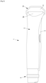
Fig 1 ] est une vue générale en perspective d'un couteau selon l'invention, - [
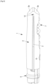
Fig 2 ] est une vue de dessus du couteau de lafigure 1 , - [
Fig 3 ] est une vue de dessous du couteau de lafigure 1 , - [
Fig 4 ] est une vue latérale du couteau de lafigure 1 , sans la structure filaire du couteau, - [
Fig 5 ] est une vue en perspective éclatée du couteau de lafigure 1 , et - [
Fig 6 ] est une vue illustrant la décapsulation d'une bouteille à l'aide du couteau de lafigure 1 . - Tel qu'illustré aux
figures 1 à 5 , un couteau 1 selon l'invention, du type couteau à lame repliable, comprend un manche 2, en bois ou en matériau plastique tel que du polyamide (avec une charge comme de la fibre de verre), et une lame 3 repliable dans le manche 2. La lame 3 est montée à rotation sur une tige de rotation 4 traversant le manche 2. - Un système à virole 5, placé à une première extrémité du manche 2, permet à l'aide d'une bague rotative selon l'axe longitudinal du manche, de bloquer en position la lame 3 une fois celle-ci déployée pour son utilisation.
- Une première virole 5a, dite virole fixe, en forme de bague fendue, est emmanchée à l'extrémité du manche 2 et est traversée par l'axe d'articulation de la lame sur le manche 2. Une deuxième virole 5b, dite virole tournante, est également en forme de bague fendue, est disposée de manière concentrique à la virole fixe 5a (à l'extrémité du manche au niveau de l'axe de rotation de la lame), et apte à tourner sur elle-même, selon l'axe longitudinal du manche 2 (
figure 5 ). - La fente prévue sur chaque virole 5a, 5b permet le passage de la lame 3 depuis la position repliée (dans le manche 2) vers la position déployée et inversement.
- Afin de bloquer la lame 3 en position déployée d'utilisation, pour des raisons de sécurité, l'utilisateur fait tourner la virole tournante 5b, ce qui fait porter la partie proximale de la lame 3 (vers le manche 2) contre la périphérie distale de la virole, empêchant le pivotement de la lame 3 et donc maintenant celle-ci en position.
- Le manche 2 comprend avantageusement un évidement latéral 6, de forme longiligne et disposé selon l'axe longitudinal du manche 2, disposé latéralement sur le manche 2 et ouvert sur l'extérieur sur toute sa longueur (
figure 3 ). - Dans l'évidement 6 est disposé un tire-bouchon 7 qui est monté à rotation sur une tige de rotation 8 transversale à l'axe du manche 2. La tige de rotation 8 du tire-bouchon 7 est orthogonale à la tige de rotation 4 de la lame 3.
- Conformément à l'invention, le couteau 1 comprend, au niveau de la deuxième extrémité du manche 2, un décapsuleur 9.
- Le décapsuleur 9 comprend une structure filaire constituée d'un fil 10, qui est par exemple métallique, et typiquement en acier inoxydable. Le fil 10 s'étend avantageusement dans un plan et est plié de manière à définir avec l'extrémité du manche 2 une boucle fermée qui délimite une ouverture de décapsulation 11.
- La structure filaire 10 est avantageusement symétrique par rapport à l'axe longitudinal du manche 2.
- Le fil 10 comprend notamment deux portions d'extrémité transversales 10a, qui constituent deux tétons qui viennent s'engager radialement dans deux logements (perçages) correspondants 12 du manche 2. Les deux logements 12 sont alignés et définissent l'axe de rotation de la structure filaire, ledit axe étant orthogonal à l'axe longitudinal du manche 2 (
figure 4 ). - Dans le mode de réalisation illustré à la
figure 5 , les deux portions d'extrémité transversales 10a du fil 10, proximales relativement au manche 2, se prolongent chacune vers l'extérieur du manche par une portion longitudinale 10b, puis par une portion inclinée 10c. Les portions inclinées 10c relient les portions longitudinales 10b à une portion transversale distale 10d, et ce en direction de l'axe du manche 2. Ainsi, la longueur de la portion transversale 10d est inférieure à la distance entre les deux portions longitudinales 10b. - Les portions d'extrémité transversales 10a et les portions longitudinales 10b délimitent sensiblement un rectangle, tandis que les portions inclinées 10c et la portion transversale centrale 10d délimitent sensiblement un trapèze isocèle.
- Les portions d'extrémité transversales 10a, les portions longitudinales 10b, les portions inclinées 10c et la portion transversale centrale 10d sont avantageusement rectilignes.
- En variante, les portions longitudinales 10b et les portions inclinées 10c peuvent être courbes ou alignées.
- L'ouverture de décapsulation 11, délimitée par la structure filaire 10 et par le manche 2, est destinée à accueillir une partie d'une capsule de bouteille.
- Une capsule de bouteille est typiquement de type bouchon couronne. Un bouchon couronne est destiné à l'obturation d'un goulot de bouteille dont le bord présente une retenue de forme semi-torique ou un filetage présentant au moins une contre-dépouille. Le bouchon couronne est principalement constitué d'un disque de métal, posé sur le goulot concentriquement à ce dernier, dont les rebords sont rabattus latéralement pour le sertir sur la retenue en formant une couronne crantée.
- La portion rectiligne transversale 10d de la structure filaire 10 constitue une zone d'accrochage du décapsuleur 9 sous au moins un cran de la couronnée crantée.
- Le décapsuleur 9 comprend également une zone d'appui 2a destinée à s'appuyer sur la partie supérieure de la capsule, au centre de la capsule. La zone d'appui 2a est une surface plane du manche 2 située à sa deuxième extrémité. Le manche 2 peut comprendre deux zones d'appui 2a, chaque zone d'appui 2a étant inclinée par rapport à l'axe du manche. Les deux zones d'appui 2a sont avantageusement symétriques par rapport à l'axe longitudinal du manche 2 (
figure 4 ). Pour un positionnement optimal du décapsuleur 9 sur la capsule, l'angle d'inclinaison entre chaque zone d'appui 2a et l'axe longitudinal du manche est compris entre 30° et 60°. - La libre rotation de la structure filaire 10 permet en outre de suspendre et d'accrocher le couteau 1 à un support.
- Pour faciliter le passage de la portion radiale centrale 10d sous la capsule, le fil a un diamètre inférieur à 3 mm, notamment à 2 mm, et de préférence compris entre 1,5 et 1,8 mm.
- Enfin, le fil 10 est avantageusement cylindrique (de section circulaire), ce qui a pour avantage que le fil ne glisse pas sous la capsule. La portion transversale centrale 10d est avantageusement cylindrique et rectiligne, ce qui permet une meilleure prise de la capsule par le décapsuleur, et ainsi le décapsuleur 9 ne s'échappe pas lors de l'opération de décapsulage.
- La
figure 6 illustre le couteau 1 en configuration opérationnelle du décapsuleur 9. - Une capsule 13 d'une bouteille 14 est engagée dans l'ouverture 11 du décapsuleur 9. La structure filaire 10 étant montée à libre rotation autour du manche 2, on peut positionner facilement et naturellement le décapsuleur 9 sur la capsule 13, et on obtient en particulier un auto-centrage du décapsuleur 9 sur la capsule 13.
- L'utilisateur engage la capsule 13 dans l'ouverture délimitée par la structure filaire, de manière que la portion transversale rectiligne 10d prenne appui sous la couronne de la capsule 13 et qu'une face d'appui 2a du manche 2 repose au centre de la capsule 13. Par une pression de bas en haut, la portion transversale rectiligne 10d entraîne quelques dents, ce qui déforme le métal et libère le col de verre enserré.
Claims (10)
- Couteau (1) comprenant un manche (2) d'axe longitudinal et une lame (3) montée à rotation à une première extrémité longitudinale du manche (2), entre une position déployée hors du manche (2) et dans l'alignement de celui-ci, et une position repliée dans un espace prévu dans le manche (2), le couteau (1) étant caractérisé en ce qu'il comprend en outre un décapsuleur (9), le décapsuleur (9) étant placé à une deuxième extrémité longitudinale du manche (2), le décapsuleur (9) comprenant une structure filaire (10) montée à libre rotation autour d'un axe orthogonal à l'axe longitudinal du manche (2), la structure filaire (10) définissant avec le manche (2) un contour fermé délimitant une ouverture de décapsulation (11) destinée à réceptionner une capsule (13), et en ce que le décapsuleur (9) comprend un élément d'appui (2a) permettant l'appui du décapsuleur (9) sur une partie supérieure de la capsule (13), ledit élément d'appui (2a) étant formé par une zone d'appui du manche (2), et un élément d'accrochage (10d) permettant l'accrochage du décapsuleur (9) sous la capsule (13), ledit élément d'accrochage (10d) étant formé par une portion rectiligne transversale de la structure filaire (10).
- Couteau (1) selon la revendication 1, caractérisé en ce que la zone d'appui (2a) du manche est une surface plane du manche (2), disposée à la deuxième extrémité longitudinale du manche (2) et inclinée par rapport à l'axe longitudinal du manche (2).
- Couteau (1) selon la revendication 1 ou 2, caractérisé en ce que la structure filaire (10) est constituée d'un fil métallique plié.
- Couteau (1) selon la revendication 3, caractérisé en ce que la structure filaire (10) est plane et en ce que le fil est de section circulaire.
- Couteau (1) selon la revendication 4, caractérisé en ce que le diamètre du fil est inférieur à 3 mm.
- Couteau (1) selon la revendication 4 ou 5, caractérisé en ce que le diamètre du fil est compris entre 1,5 et 1,8 mm.
- Couteau (1) selon l'une des revendications 1 à 6, caractérisé en ce que la structure filaire (10) comprend successivement, depuis la deuxième extrémité longitudinale du manche (2) et en s'éloignant longitudinalement de ladite deuxième extrémité longitudinale : a) deux portions d'extrémité transversales (10a) engagées chacune dans un logement transversal (12) du manche (2), b) deux portions longitudinales (10b) reliées chacune en amont à une portion d'extrémité transversale (10a), c) deux portions inclinées (10c) en direction de l'axe longitudinal du manche (2) et reliées chacune en amont à une portion longitudinale, et d) ladite portion rectiligne transversale (10d) qui est reliée aux deux portions inclinées (10c).
- Couteau (1) selon l'une des revendications 1 à 7, caractérisé en ce qu'il comprend une première virole (5a), dite virole fixe, en forme de bague fendue, emmanchée à la première extrémité du manche (2) et traversée par une tige de rotation (4) sur laquelle la lame (3) est montée à rotation, et une deuxième virole (5b), dite virole tournante, en forme de bague fendue, disposée à la première extrémité du manche (2) au niveau de l'axe de rotation de la lame (3), de manière concentrique à la virole fixe (5a), et apte à tourner sur elle-même selon l'axe longitudinal du manche (2).
- Couteau (1) selon l'une des revendications 1 à 8, caractérisé en ce qu'il comprend un évidement de rangement (6) dans lequel est disposé un tire-bouchon (7).
- Utilisation d'un couteau (1) selon l'une des revendications 1 à 9 pour la décapsulation d'une bouteille (14).
Applications Claiming Priority (1)
| Application Number | Priority Date | Filing Date | Title |
|---|---|---|---|
| FR2300252A FR3144769B1 (fr) | 2023-01-10 | 2023-01-10 | Couteau à lame articulée muni d’un décapsuleur |
Publications (2)
| Publication Number | Publication Date |
|---|---|
| EP4400280A1 true EP4400280A1 (fr) | 2024-07-17 |
| EP4400280B1 EP4400280B1 (fr) | 2024-11-20 |
Family
ID=85727068
Family Applications (1)
| Application Number | Title | Priority Date | Filing Date |
|---|---|---|---|
| EP23216373.3A Active EP4400280B1 (fr) | 2023-01-10 | 2023-12-13 | Couteau à lame articulée muni d'un décapsuleur |
Country Status (5)
| Country | Link |
|---|---|
| US (1) | US20240227217A1 (fr) |
| EP (1) | EP4400280B1 (fr) |
| JP (1) | JP2024098484A (fr) |
| ES (1) | ES3000309T3 (fr) |
| FR (1) | FR3144769B1 (fr) |
Families Citing this family (1)
| Publication number | Priority date | Publication date | Assignee | Title |
|---|---|---|---|---|
| FR3144769B1 (fr) * | 2023-01-10 | 2024-12-13 | Opinel Sas | Couteau à lame articulée muni d’un décapsuleur |
Citations (3)
| Publication number | Priority date | Publication date | Assignee | Title |
|---|---|---|---|---|
| EP0860396A1 (fr) * | 1997-02-14 | 1998-08-26 | Francisco José Traspuesto Miguel | Tire-bouchon avec bras d'appui de longueur variable |
| US20030110572A1 (en) * | 2001-12-14 | 2003-06-19 | Dupre Percival | Multi-purpose opener |
| US20110179581A1 (en) * | 2010-01-22 | 2011-07-28 | Peter Hunkele | Multi-purpose tool |
Family Cites Families (7)
| Publication number | Priority date | Publication date | Assignee | Title |
|---|---|---|---|---|
| DE647844C (de) * | 1935-11-27 | 1937-07-14 | Otto Altenbach | Taschenmesser mit Werkzeugen |
| US2089536A (en) * | 1936-03-17 | 1937-08-10 | Philip T Champlin | Combined knife and cap remover |
| US2311107A (en) * | 1942-12-30 | 1943-02-16 | Fraties Clifford A De | Utility pocket knife |
| FR2519957B1 (fr) * | 1982-01-20 | 1986-07-18 | Souhart Jacques | Dispositif pour decouper le fond d'une capsule d'un seul tenant coiffant le goulot d'une bouteille |
| US4409864A (en) * | 1982-04-12 | 1983-10-18 | Thomas Gaskins | Bottle opener |
| US4805250A (en) * | 1987-09-25 | 1989-02-21 | Dugas Theodore F | Blade pick and well cleaner |
| FR3144769B1 (fr) * | 2023-01-10 | 2024-12-13 | Opinel Sas | Couteau à lame articulée muni d’un décapsuleur |
-
2023
- 2023-01-10 FR FR2300252A patent/FR3144769B1/fr active Active
- 2023-10-06 JP JP2023174116A patent/JP2024098484A/ja active Pending
- 2023-12-13 EP EP23216373.3A patent/EP4400280B1/fr active Active
- 2023-12-13 ES ES23216373T patent/ES3000309T3/es active Active
-
2024
- 2024-01-09 US US18/408,418 patent/US20240227217A1/en active Pending
Patent Citations (3)
| Publication number | Priority date | Publication date | Assignee | Title |
|---|---|---|---|---|
| EP0860396A1 (fr) * | 1997-02-14 | 1998-08-26 | Francisco José Traspuesto Miguel | Tire-bouchon avec bras d'appui de longueur variable |
| US20030110572A1 (en) * | 2001-12-14 | 2003-06-19 | Dupre Percival | Multi-purpose opener |
| US20110179581A1 (en) * | 2010-01-22 | 2011-07-28 | Peter Hunkele | Multi-purpose tool |
Also Published As
| Publication number | Publication date |
|---|---|
| FR3144769B1 (fr) | 2024-12-13 |
| JP2024098484A (ja) | 2024-07-23 |
| ES3000309T3 (en) | 2025-02-28 |
| US20240227217A1 (en) | 2024-07-11 |
| EP4400280B1 (fr) | 2024-11-20 |
| FR3144769A1 (fr) | 2024-07-12 |
Similar Documents
| Publication | Publication Date | Title |
|---|---|---|
| FR2951152A1 (fr) | Tire-bouchon a levier a double point d'appui et son procede d'utilisation | |
| EP1677633A1 (fr) | Dispositif coupe-cigares | |
| FR2775679A1 (fr) | Ouvre-boite | |
| EP4400280B1 (fr) | Couteau à lame articulée muni d'un décapsuleur | |
| EP4135930A1 (fr) | Fourreau aiguiseur adapte pour recevoir un couteau et combinaison d'un tel fourreau et d'un couteau | |
| EP1194269A1 (fr) | Couteau | |
| CA3004993C (fr) | Tire-bouchon a levier | |
| FR3005307A1 (fr) | Tire-bouchon pour bouteille a liquide effervescent | |
| FR2939347A1 (fr) | Ote-agrafe combine a une agrafeuse | |
| FR2809097A1 (fr) | Dispositif de fixation d'un decapsuleur de bouchon couronne sur les doigts de la main | |
| EP2593395B1 (fr) | Tire-bouchon à double levier | |
| FR2519957A1 (fr) | Dispositif pour decouper le fond d'une capsule d'un seul tenant coiffant le goulot d'une bouteille | |
| WO2021209195A1 (fr) | Fourreau aiguiseur adapte a recevoir un couteau et combinaison d'un tel fourreau et d'un couteau | |
| EP2566612B1 (fr) | Batteur melangeur a tete pivotante | |
| FR3109112A1 (fr) | Combinaison d’un fourreau et d’un couteau | |
| EP3320818B1 (fr) | Dispositif de traitement d'aliments muni d'un système de fixation d'un outil | |
| EP3067169B1 (fr) | Couteau à lame articulée pourvu d'une virole de blocage ameliorée | |
| FR2977821A1 (fr) | Pince serre-joint | |
| EP0207823A1 (fr) | Pince pour l'ouverture de bocaux pressurisés | |
| FR2734254A1 (fr) | Tire-bouchon a levier | |
| FR2912337A1 (fr) | Dispositif d'ouverture semi-automatique d'un couteau. | |
| FR2908758A1 (fr) | Tire-bouchon a machoires pourvu de moyens de decoupe de la capsule | |
| WO2026052919A1 (fr) | Système d'étalement d'un cordon de pâte le long d'une paroi interne d'une chambre cylindrique | |
| FR2771061A1 (fr) | Essuie-glace de vehicule automobile comportant des moyens de verrouillage en position relevee | |
| FR2875379A1 (fr) | Dispositif pour couper les tiges de fleur en biseau |
Legal Events
| Date | Code | Title | Description |
|---|---|---|---|
| PUAI | Public reference made under article 153(3) epc to a published international application that has entered the european phase |
Free format text: ORIGINAL CODE: 0009012 |
|
| STAA | Information on the status of an ep patent application or granted ep patent |
Free format text: STATUS: THE APPLICATION HAS BEEN PUBLISHED |
|
| AK | Designated contracting states |
Kind code of ref document: A1 Designated state(s): AL AT BE BG CH CY CZ DE DK EE ES FI FR GB GR HR HU IE IS IT LI LT LU LV MC ME MK MT NL NO PL PT RO RS SE SI SK SM TR |
|
| STAA | Information on the status of an ep patent application or granted ep patent |
Free format text: STATUS: REQUEST FOR EXAMINATION WAS MADE |
|
| 17P | Request for examination filed |
Effective date: 20240813 |
|
| GRAP | Despatch of communication of intention to grant a patent |
Free format text: ORIGINAL CODE: EPIDOSNIGR1 |
|
| RBV | Designated contracting states (corrected) |
Designated state(s): AL AT BE BG CH CY CZ DE DK EE ES FI FR GB GR HR HU IE IS IT LI LT LU LV MC ME MK MT NL NO PL PT RO RS SE SI SK SM TR |
|
| STAA | Information on the status of an ep patent application or granted ep patent |
Free format text: STATUS: GRANT OF PATENT IS INTENDED |
|
| GRAS | Grant fee paid |
Free format text: ORIGINAL CODE: EPIDOSNIGR3 |
|
| GRAA | (expected) grant |
Free format text: ORIGINAL CODE: 0009210 |
|
| STAA | Information on the status of an ep patent application or granted ep patent |
Free format text: STATUS: THE PATENT HAS BEEN GRANTED |
|
| INTG | Intention to grant announced |
Effective date: 20240919 |
|
| AK | Designated contracting states |
Kind code of ref document: B1 Designated state(s): AL AT BE BG CH CY CZ DE DK EE ES FI FR GB GR HR HU IE IS IT LI LT LU LV MC ME MK MT NL NO PL PT RO RS SE SI SK SM TR |
|
| REG | Reference to a national code |
Ref country code: GB Ref legal event code: FG4D Free format text: NOT ENGLISH |
|
| REG | Reference to a national code |
Ref country code: CH Ref legal event code: EP |
|
| P01 | Opt-out of the competence of the unified patent court (upc) registered |
Free format text: CASE NUMBER: APP_58135/2024 Effective date: 20241024 |
|
| REG | Reference to a national code |
Ref country code: DE Ref legal event code: R096 Ref document number: 602023001107 Country of ref document: DE |
|
| REG | Reference to a national code |
Ref country code: IE Ref legal event code: FG4D Free format text: LANGUAGE OF EP DOCUMENT: FRENCH |
|
| REG | Reference to a national code |
Ref country code: ES Ref legal event code: FG2A Ref document number: 3000309 Country of ref document: ES Kind code of ref document: T3 Effective date: 20250228 |
|
| REG | Reference to a national code |
Ref country code: LT Ref legal event code: MG9D |
|
| REG | Reference to a national code |
Ref country code: NL Ref legal event code: MP Effective date: 20241120 |
|
| PG25 | Lapsed in a contracting state [announced via postgrant information from national office to epo] |
Ref country code: HR Free format text: LAPSE BECAUSE OF FAILURE TO SUBMIT A TRANSLATION OF THE DESCRIPTION OR TO PAY THE FEE WITHIN THE PRESCRIBED TIME-LIMIT Effective date: 20241120 Ref country code: PT Free format text: LAPSE BECAUSE OF FAILURE TO SUBMIT A TRANSLATION OF THE DESCRIPTION OR TO PAY THE FEE WITHIN THE PRESCRIBED TIME-LIMIT Effective date: 20250320 Ref country code: IS Free format text: LAPSE BECAUSE OF FAILURE TO SUBMIT A TRANSLATION OF THE DESCRIPTION OR TO PAY THE FEE WITHIN THE PRESCRIBED TIME-LIMIT Effective date: 20250320 |
|
| PG25 | Lapsed in a contracting state [announced via postgrant information from national office to epo] |
Ref country code: FI Free format text: LAPSE BECAUSE OF FAILURE TO SUBMIT A TRANSLATION OF THE DESCRIPTION OR TO PAY THE FEE WITHIN THE PRESCRIBED TIME-LIMIT Effective date: 20241120 Ref country code: NL Free format text: LAPSE BECAUSE OF FAILURE TO SUBMIT A TRANSLATION OF THE DESCRIPTION OR TO PAY THE FEE WITHIN THE PRESCRIBED TIME-LIMIT Effective date: 20241120 |
|
| REG | Reference to a national code |
Ref country code: AT Ref legal event code: MK05 Ref document number: 1743176 Country of ref document: AT Kind code of ref document: T Effective date: 20241120 |
|
| PG25 | Lapsed in a contracting state [announced via postgrant information from national office to epo] |
Ref country code: BG Free format text: LAPSE BECAUSE OF FAILURE TO SUBMIT A TRANSLATION OF THE DESCRIPTION OR TO PAY THE FEE WITHIN THE PRESCRIBED TIME-LIMIT Effective date: 20241120 |
|
| PG25 | Lapsed in a contracting state [announced via postgrant information from national office to epo] |
Ref country code: NO Free format text: LAPSE BECAUSE OF FAILURE TO SUBMIT A TRANSLATION OF THE DESCRIPTION OR TO PAY THE FEE WITHIN THE PRESCRIBED TIME-LIMIT Effective date: 20250220 |
|
| PG25 | Lapsed in a contracting state [announced via postgrant information from national office to epo] |
Ref country code: LV Free format text: LAPSE BECAUSE OF FAILURE TO SUBMIT A TRANSLATION OF THE DESCRIPTION OR TO PAY THE FEE WITHIN THE PRESCRIBED TIME-LIMIT Effective date: 20241120 Ref country code: GR Free format text: LAPSE BECAUSE OF FAILURE TO SUBMIT A TRANSLATION OF THE DESCRIPTION OR TO PAY THE FEE WITHIN THE PRESCRIBED TIME-LIMIT Effective date: 20250221 Ref country code: AT Free format text: LAPSE BECAUSE OF FAILURE TO SUBMIT A TRANSLATION OF THE DESCRIPTION OR TO PAY THE FEE WITHIN THE PRESCRIBED TIME-LIMIT Effective date: 20241120 |
|
| PG25 | Lapsed in a contracting state [announced via postgrant information from national office to epo] |
Ref country code: PL Free format text: LAPSE BECAUSE OF FAILURE TO SUBMIT A TRANSLATION OF THE DESCRIPTION OR TO PAY THE FEE WITHIN THE PRESCRIBED TIME-LIMIT Effective date: 20241120 |
|
| PG25 | Lapsed in a contracting state [announced via postgrant information from national office to epo] |
Ref country code: IT Free format text: LAPSE BECAUSE OF NON-PAYMENT OF DUE FEES Effective date: 20241213 |
|
| PG25 | Lapsed in a contracting state [announced via postgrant information from national office to epo] |
Ref country code: RS Free format text: LAPSE BECAUSE OF FAILURE TO SUBMIT A TRANSLATION OF THE DESCRIPTION OR TO PAY THE FEE WITHIN THE PRESCRIBED TIME-LIMIT Effective date: 20250220 |
|
| PG25 | Lapsed in a contracting state [announced via postgrant information from national office to epo] |
Ref country code: SM Free format text: LAPSE BECAUSE OF FAILURE TO SUBMIT A TRANSLATION OF THE DESCRIPTION OR TO PAY THE FEE WITHIN THE PRESCRIBED TIME-LIMIT Effective date: 20241120 |
|
| PG25 | Lapsed in a contracting state [announced via postgrant information from national office to epo] |
Ref country code: DK Free format text: LAPSE BECAUSE OF FAILURE TO SUBMIT A TRANSLATION OF THE DESCRIPTION OR TO PAY THE FEE WITHIN THE PRESCRIBED TIME-LIMIT Effective date: 20241120 |
|
| PG25 | Lapsed in a contracting state [announced via postgrant information from national office to epo] |
Ref country code: EE Free format text: LAPSE BECAUSE OF FAILURE TO SUBMIT A TRANSLATION OF THE DESCRIPTION OR TO PAY THE FEE WITHIN THE PRESCRIBED TIME-LIMIT Effective date: 20241120 |
|
| PG25 | Lapsed in a contracting state [announced via postgrant information from national office to epo] |
Ref country code: RO Free format text: LAPSE BECAUSE OF FAILURE TO SUBMIT A TRANSLATION OF THE DESCRIPTION OR TO PAY THE FEE WITHIN THE PRESCRIBED TIME-LIMIT Effective date: 20241120 |
|
| PG25 | Lapsed in a contracting state [announced via postgrant information from national office to epo] |
Ref country code: SK Free format text: LAPSE BECAUSE OF FAILURE TO SUBMIT A TRANSLATION OF THE DESCRIPTION OR TO PAY THE FEE WITHIN THE PRESCRIBED TIME-LIMIT Effective date: 20241120 |
|
| PG25 | Lapsed in a contracting state [announced via postgrant information from national office to epo] |
Ref country code: CZ Free format text: LAPSE BECAUSE OF FAILURE TO SUBMIT A TRANSLATION OF THE DESCRIPTION OR TO PAY THE FEE WITHIN THE PRESCRIBED TIME-LIMIT Effective date: 20241120 |
|
| REG | Reference to a national code |
Ref country code: DE Ref legal event code: R097 Ref document number: 602023001107 Country of ref document: DE |
|
| PG25 | Lapsed in a contracting state [announced via postgrant information from national office to epo] |
Ref country code: SE Free format text: LAPSE BECAUSE OF FAILURE TO SUBMIT A TRANSLATION OF THE DESCRIPTION OR TO PAY THE FEE WITHIN THE PRESCRIBED TIME-LIMIT Effective date: 20241120 |
|
| PG25 | Lapsed in a contracting state [announced via postgrant information from national office to epo] |
Ref country code: MC Free format text: LAPSE BECAUSE OF FAILURE TO SUBMIT A TRANSLATION OF THE DESCRIPTION OR TO PAY THE FEE WITHIN THE PRESCRIBED TIME-LIMIT Effective date: 20241120 |
|
| PLBE | No opposition filed within time limit |
Free format text: ORIGINAL CODE: 0009261 |
|
| STAA | Information on the status of an ep patent application or granted ep patent |
Free format text: STATUS: NO OPPOSITION FILED WITHIN TIME LIMIT |
|
| 26N | No opposition filed |
Effective date: 20250821 |
|
| PGFP | Annual fee paid to national office [announced via postgrant information from national office to epo] |
Ref country code: DE Payment date: 20251016 Year of fee payment: 3 |
|
| PG25 | Lapsed in a contracting state [announced via postgrant information from national office to epo] |
Ref country code: IT Free format text: LAPSE BECAUSE OF NON-PAYMENT OF DUE FEES Effective date: 20241213 |
|
| PGRI | Patent reinstated in contracting state [announced from national office to epo] |
Ref country code: IT Effective date: 20241231 |
|
| PGFP | Annual fee paid to national office [announced via postgrant information from national office to epo] |
Ref country code: FR Payment date: 20251015 Year of fee payment: 3 |
|
| PGFP | Annual fee paid to national office [announced via postgrant information from national office to epo] |
Ref country code: ES Payment date: 20260320 Year of fee payment: 3 |
|
| PGFP | Annual fee paid to national office [announced via postgrant information from national office to epo] |
Ref country code: IT Payment date: 20251231 Year of fee payment: 3 |