EP4400330A1 - Pneu de motocyclette - Google Patents
Pneu de motocyclette Download PDFInfo
- Publication number
- EP4400330A1 EP4400330A1 EP23209301.3A EP23209301A EP4400330A1 EP 4400330 A1 EP4400330 A1 EP 4400330A1 EP 23209301 A EP23209301 A EP 23209301A EP 4400330 A1 EP4400330 A1 EP 4400330A1
- Authority
- EP
- European Patent Office
- Prior art keywords
- tire
- belt
- layer
- circumferential direction
- curvature
- Prior art date
- Legal status (The legal status is an assumption and is not a legal conclusion. Google has not performed a legal analysis and makes no representation as to the accuracy of the status listed.)
- Granted
Links
Images


Classifications
-
- B—PERFORMING OPERATIONS; TRANSPORTING
- B60—VEHICLES IN GENERAL
- B60C—VEHICLE TYRES; TYRE INFLATION; TYRE CHANGING; CONNECTING VALVES TO INFLATABLE ELASTIC BODIES IN GENERAL; DEVICES OR ARRANGEMENTS RELATED TO TYRES
- B60C9/00—Reinforcements or ply arrangement of pneumatic tyres
- B60C9/18—Structure or arrangement of belts or breakers, crown-reinforcing or cushioning layers
- B60C9/20—Structure or arrangement of belts or breakers, crown-reinforcing or cushioning layers built-up from rubberised plies each having all cords arranged substantially parallel
- B60C9/2003—Structure or arrangement of belts or breakers, crown-reinforcing or cushioning layers built-up from rubberised plies each having all cords arranged substantially parallel characterised by the materials of the belt cords
- B60C9/2009—Structure or arrangement of belts or breakers, crown-reinforcing or cushioning layers built-up from rubberised plies each having all cords arranged substantially parallel characterised by the materials of the belt cords comprising plies of different materials
-
- B—PERFORMING OPERATIONS; TRANSPORTING
- B60—VEHICLES IN GENERAL
- B60C—VEHICLE TYRES; TYRE INFLATION; TYRE CHANGING; CONNECTING VALVES TO INFLATABLE ELASTIC BODIES IN GENERAL; DEVICES OR ARRANGEMENTS RELATED TO TYRES
- B60C9/00—Reinforcements or ply arrangement of pneumatic tyres
- B60C9/18—Structure or arrangement of belts or breakers, crown-reinforcing or cushioning layers
- B60C9/20—Structure or arrangement of belts or breakers, crown-reinforcing or cushioning layers built-up from rubberised plies each having all cords arranged substantially parallel
- B60C9/22—Structure or arrangement of belts or breakers, crown-reinforcing or cushioning layers built-up from rubberised plies each having all cords arranged substantially parallel the plies being arranged with all cords disposed along the circumference of the tyre
-
- B—PERFORMING OPERATIONS; TRANSPORTING
- B60—VEHICLES IN GENERAL
- B60C—VEHICLE TYRES; TYRE INFLATION; TYRE CHANGING; CONNECTING VALVES TO INFLATABLE ELASTIC BODIES IN GENERAL; DEVICES OR ARRANGEMENTS RELATED TO TYRES
- B60C11/00—Tyre tread bands; Tread patterns; Anti-skid inserts
- B60C11/0083—Tyre tread bands; Tread patterns; Anti-skid inserts characterised by the curvature of the tyre tread
-
- B—PERFORMING OPERATIONS; TRANSPORTING
- B60—VEHICLES IN GENERAL
- B60C—VEHICLE TYRES; TYRE INFLATION; TYRE CHANGING; CONNECTING VALVES TO INFLATABLE ELASTIC BODIES IN GENERAL; DEVICES OR ARRANGEMENTS RELATED TO TYRES
- B60C9/00—Reinforcements or ply arrangement of pneumatic tyres
- B60C9/18—Structure or arrangement of belts or breakers, crown-reinforcing or cushioning layers
- B60C9/20—Structure or arrangement of belts or breakers, crown-reinforcing or cushioning layers built-up from rubberised plies each having all cords arranged substantially parallel
- B60C9/2003—Structure or arrangement of belts or breakers, crown-reinforcing or cushioning layers built-up from rubberised plies each having all cords arranged substantially parallel characterised by the materials of the belt cords
- B60C9/2006—Structure or arrangement of belts or breakers, crown-reinforcing or cushioning layers built-up from rubberised plies each having all cords arranged substantially parallel characterised by the materials of the belt cords consisting of steel cord plies only
-
- B—PERFORMING OPERATIONS; TRANSPORTING
- B60—VEHICLES IN GENERAL
- B60C—VEHICLE TYRES; TYRE INFLATION; TYRE CHANGING; CONNECTING VALVES TO INFLATABLE ELASTIC BODIES IN GENERAL; DEVICES OR ARRANGEMENTS RELATED TO TYRES
- B60C9/00—Reinforcements or ply arrangement of pneumatic tyres
- B60C9/18—Structure or arrangement of belts or breakers, crown-reinforcing or cushioning layers
- B60C9/20—Structure or arrangement of belts or breakers, crown-reinforcing or cushioning layers built-up from rubberised plies each having all cords arranged substantially parallel
- B60C9/22—Structure or arrangement of belts or breakers, crown-reinforcing or cushioning layers built-up from rubberised plies each having all cords arranged substantially parallel the plies being arranged with all cords disposed along the circumference of the tyre
- B60C9/2204—Structure or arrangement of belts or breakers, crown-reinforcing or cushioning layers built-up from rubberised plies each having all cords arranged substantially parallel the plies being arranged with all cords disposed along the circumference of the tyre obtained by circumferentially narrow strip winding
-
- B—PERFORMING OPERATIONS; TRANSPORTING
- B60—VEHICLES IN GENERAL
- B60C—VEHICLE TYRES; TYRE INFLATION; TYRE CHANGING; CONNECTING VALVES TO INFLATABLE ELASTIC BODIES IN GENERAL; DEVICES OR ARRANGEMENTS RELATED TO TYRES
- B60C9/00—Reinforcements or ply arrangement of pneumatic tyres
- B60C9/18—Structure or arrangement of belts or breakers, crown-reinforcing or cushioning layers
- B60C9/28—Structure or arrangement of belts or breakers, crown-reinforcing or cushioning layers characterised by the belt or breaker dimensions or curvature relative to carcass
-
- B—PERFORMING OPERATIONS; TRANSPORTING
- B60—VEHICLES IN GENERAL
- B60C—VEHICLE TYRES; TYRE INFLATION; TYRE CHANGING; CONNECTING VALVES TO INFLATABLE ELASTIC BODIES IN GENERAL; DEVICES OR ARRANGEMENTS RELATED TO TYRES
- B60C9/00—Reinforcements or ply arrangement of pneumatic tyres
- B60C9/18—Structure or arrangement of belts or breakers, crown-reinforcing or cushioning layers
- B60C9/20—Structure or arrangement of belts or breakers, crown-reinforcing or cushioning layers built-up from rubberised plies each having all cords arranged substantially parallel
- B60C2009/2012—Structure or arrangement of belts or breakers, crown-reinforcing or cushioning layers built-up from rubberised plies each having all cords arranged substantially parallel with particular configuration of the belt cords in the respective belt layers
- B60C2009/2025—Structure or arrangement of belts or breakers, crown-reinforcing or cushioning layers built-up from rubberised plies each having all cords arranged substantially parallel with particular configuration of the belt cords in the respective belt layers with angle different or variable in the same layer
-
- B—PERFORMING OPERATIONS; TRANSPORTING
- B60—VEHICLES IN GENERAL
- B60C—VEHICLE TYRES; TYRE INFLATION; TYRE CHANGING; CONNECTING VALVES TO INFLATABLE ELASTIC BODIES IN GENERAL; DEVICES OR ARRANGEMENTS RELATED TO TYRES
- B60C9/00—Reinforcements or ply arrangement of pneumatic tyres
- B60C9/18—Structure or arrangement of belts or breakers, crown-reinforcing or cushioning layers
- B60C9/20—Structure or arrangement of belts or breakers, crown-reinforcing or cushioning layers built-up from rubberised plies each having all cords arranged substantially parallel
- B60C9/22—Structure or arrangement of belts or breakers, crown-reinforcing or cushioning layers built-up from rubberised plies each having all cords arranged substantially parallel the plies being arranged with all cords disposed along the circumference of the tyre
- B60C2009/2214—Structure or arrangement of belts or breakers, crown-reinforcing or cushioning layers built-up from rubberised plies each having all cords arranged substantially parallel the plies being arranged with all cords disposed along the circumference of the tyre characterised by the materials of the zero degree ply cords
-
- B—PERFORMING OPERATIONS; TRANSPORTING
- B60—VEHICLES IN GENERAL
- B60C—VEHICLE TYRES; TYRE INFLATION; TYRE CHANGING; CONNECTING VALVES TO INFLATABLE ELASTIC BODIES IN GENERAL; DEVICES OR ARRANGEMENTS RELATED TO TYRES
- B60C2200/00—Tyres specially adapted for particular applications
- B60C2200/10—Tyres specially adapted for particular applications for motorcycles, scooters or the like
Definitions
- the present invention relates to a motorcycle tire.
- Patent Document 1 discloses a motorcycle tire provided, in the tread portion, with a belt layer and a band layer.
- the belt layer comprises a belt ply of belt cords.
- the band layer is disposed radially outside the belt layer and comprises a band cord arranged at an angle of not more than 5 degrees with respect to the tire circumferential direction.
- Patent Document 1 Japanese Patent No. 6,946,646
- the tread crown region is strongly constricted by the band layer, therefore, excellent straight-running stability can be exhibited.
- the outer diameter of the tire is liable to increase in the tread shoulder regions, and the radius of curvature of the ground contacting surface of the tread portion increases accordingly, which may impair the cornering performance of the tire.
- the present invention was made in view of the above-mentioned circumstances, and a primary objective of the present invention is to provide a motorcycle tire capable of achieving both straight-running stability and cornering performance.
- a motorcycle tire comprises:
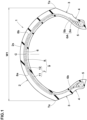
- FIG. 1 is a tire meridian cross-sectional view of a motorcycle tire 1 as an embodiment of the present invention under its standard state including a rotational axis of the tire.
- the motorcycle tire 1 is for the front wheel of a motorcycle suitable for on-road sports riding.
- the present invention is not limited to the present embodiment.
- the "standard state” means a state of the tire when mounted on a standard wheel rim, and inflated to a standard tire pressure, but loaded with no tire load.
- the “standard wheel rim” is a wheel rim specified for the tire in a standard system including standards on which the tire is based, for example, the "Standard rim” in JATMA, "Design Rim” in TRA, “Measuring Rim” in ETRTO.
- the “standard tire pressure” is the air pressure specified for the tire in the above-mentioned standard system, for example, the “maximum air pressure” in JATMA, "INFLATION PRESSURE” in ETRTO, and the maximum air pressure listed in the table "TIRE LOAD LIMITS AT VARIOUS COLD INFLATION PRESSURES" in TRA.
- the "standard state” means a standard usage state depending on the purpose of use of the tire and in a condition in which the tire is not attached to a vehicle and no tire load is applied.
- the tire 1 in the present embodiment comprises a tread portion 2, a pair of sidewall portions 3, and a pair of bead portions 4.
- the sidewall portions 3 extend radially inwardly from the ends in the tire axial direction of the tread portion 2.
- the bead portions 4 are positioned at the inner ends in the tire radial direction of the sidewall portions 3.
- Each of the bead portions 4 is provided with a bead core 5 embedded therein.
- the tread portion 2 has a pair of tread edges Te and a ground contacting surface 2s therebetween, and the ground contacting surface is curved in an arc profile convex outward in the tire radial direction so that a sufficient ground contact area can be secured even when cornering at a large bank angle.
- the tread edges Te correspond to the axially outermost ends of the ground contacting surface 2s of the tread portion 2, and may contact with the road surface when cornering at near the maximum bank angle.
- the tire 1 comprises a carcass 6 extending between the bead portions 4 through the tread portion 2 and the sidewall portions 3.
- the carcass 6 is composed of one or more carcass plies 6A, in this embodiment, composed of only one carcass ply 6A.
- the carcass ply 6A is made of rubberized carcass cords extending between the bead portions 4 through the tread portion 2 and the sidewall portions 3, and is turned up around the bead core 5 in each bead portion 4 from the inside to outside of the tire so as to form a pair of turned-up portions 6b and a main portion 6a therebetween.
- the tread portion 2 is provided with tread reinforcing layers 9 disposed radially outside the carcass 6.
- the tread reinforcing layers 9 include a belt layer 7 and a band layer 8 on the radially outside of the belt layer 7.
- the belt layer 7 is composed of at least one belt ply of rubberized belt cords 15 arranged at an angle of from 10 to 40 degrees with respect to the tire circumferential direction.
- the belt layer 7 is composed of a first belt ply 11 disposed adjacently to the carcass 6, and a second belt ply 12 disposed on the radially outside of the first belt ply 11.
- the belt layer 7 is composed of only two cross belt plies 11 and 12.
- the band layer 8 includes at least one band cord 20 wound spirally and circumferentially of the tire.
- the band layer 8 may be a jointless band in which one or more band cords are continuously wound spirally and circumferentially of the tire.
- the band layer 8 may be one in which a band cord 20 coated with topping rubber is wound, or a band cord 20 not covered with rubber may be wound on a rubber sheet.
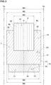
- the developed width w3 of the band layer 8 is smaller than the developed width W2 of the belt layer 7.
- the developed width means the dimension in the tire axial direction when the band layer 8 or the belt layer 7 is developed flatly.
- FIG. 4 shows a profile of the ground contacting surface 2s of the tread portion 2 in the meridian cross section of the tire 1 including the rotational axis of the tire when mounted on a standard wheel rim at an internal pressure of 10 kPa (hereinafter referred to as the "low internal pressure state").
- the radius of curvature Rc of the ground contacting surface 2s in a crown region 21 passing through the tire equator C is less than 95% of the cross-sectional width w1 of the tire (shown in FIG. 1 ).
- the cross-sectional width w1 of the tire corresponds to the width in the tire axial direction in the standard state of the tire.
- the radius of curvature Rb of the ground contacting surface 2s in shoulder regions 22 respectively on the outer side in the tire axial direction than axial edges 8a and 8b (shown in FIG. 3 ) of the band layer 8, is larger than the radius of curvature Rc.
- FIG. 4 two straight lines 25 respectively passing through the axial edges 8a and 8b of the band layer 8 orthogonally to the ground contacting surface 2s are shown.
- the crown region 21 is defined as extending between the two straight lines 25, and the shoulder regions 22 are respectively defined as being axially outside the two straight lines 25.
- the motorcycle tire 1 can achieve both straight running stability and cornering performance.
- the reason may be as follows.
- the band layer 8 can effectively suppresses the increase of the tire outer diameter in the crown region 21 during highspeed running, and can provide excellent straight-running stability.
- the belt layer 7 can exerts a large cornering force, and excellent cornering performance can be obtained.
- the outer diameter of a conventional motorcycle tire of which tread portion is reinforced with two cross belt plies is liable to increase in the shoulder regions than in the crown region, which results in deterioration of the cornering performance.
- the tread profile in the low internal pressure state is defined so that the radius of curvature Rc in the crown region 21 is relatively small as described above, even if the tire outer diameter is changed by applying a normal internal pressure, the change in the radius of curvature of the tread profile mainly occurs in the crown region 21, and hardly occurs in the shoulder regions 22, therefore, the radius of curvature in the shoulder regions 22 is maintained appropriately without becoming excessively large.
- the tread profile in a normally inflated state is optimized to prevent the deterioration of the cornering performance.
- each configuration described below represents a specific aspect of the present embodiment. Therefore, the present invention can exhibit the above effects even if it does not have the configuration described below. Further, even if any one of the configurations described below is applied singly to the tire of the present invention having the features described above, an improvement in performance corresponding to each configuration can be expected. Furthermore, when some of the respective configurations described below are applied in combination, it is possible to expect a combined improvement in performance according to the respective configurations.
- the angle ⁇ 1, ⁇ 2 of the belt cords 15 can be expressed as an average angle of a belt cord 15.
- the average angle is obtained by dividing the length of the belt cord into minute parts having an equal length, and summing up angles of the minute parts, and then dividing the sum total by the number of the minute parts.
- the length of each minute part is preferably at most 5 mm.
- the angle of the belt cords 16 becomes maximum at the edges in the tire axial direction of the first belt ply 11 and is larger than at the tire equator C.
- the angle of the belt cords 16 in the shoulder regions 22 is larger than the angle of the belt cords 16 in the crown region 21.
- the angle means the average angle in the above sense.
- the developed width w5 of the first belt ply 11 and the developed width w6 of the second belt ply 12 are set in a range from 80% to 100%, preferably from 90% to 95% of the developed width W4 of the tread portion 2.
- the developed width W6 of the second belt ply 12 is larger than the developed width W5 of the first belt ply 11.
- damage starting from near the axial edges of the first belt ply 11 is suppressed, and the durability of the shoulder regions 22 can be improved.
- the developed width w4 of the tread portion 2 corresponds to the distance in the tire axial direction between the tread edges Te when the ground contacting surface 2s of the tread portion 2 is developed flatly.
- the average angle ⁇ 2 of the belt cords 17 of the second belt ply 12 is in a range from 10 to 40 degrees with respect to the tire circumferential direction. Further, the maximum angle of the belt cords 17 with respect to the tire circumferential direction at the edges in the tire axial direction of the second belt ply 12 is larger than the angle of the belt cords 17 with respect to the tire circumferential direction at the tire equator c.
- the angle of the belt cords 17 in the shoulder regions 22 is larger than the angle of the belt cords 17 in the crown region 21.
- the angle means the average angle in the above sense.
- the belt cords 15 (16, 17), organic fiber cords such as polyester, nylon, and aramid can be suitably used. But, the belt cords 15 are not limited to such materials.
- the developed width w3 of the band layer 8 in this example is in a range from 20% to 80% of the developed width W4 of the tread portion 2.
- the developed width w3 of the band layer 8 is relatively small.
- the developed width w3 of the band layer 8 is preferably set in a range from 20% to 60%, more preferably 20% to 40% of the developed width W4 of the tread portion 2.
- the rupture strength of the band cord 20 is greater than the rupture strength of the belt cord 15. From this point of view, it is desirable that the band cord 20 is a steel cord when the belt cords 15 are organic fiber cords as in the present embodiment in particular.
- the radius of curvature Rc in the crown region 21 is in a range from 40% to 60% of the cross-sectional width w1 of the tire.
- the radius of curvature Rb in the shoulder regions 22 is not less than 2.0 times, more preferably not less than 2.5 times, but not more than 3.5 times, more preferably not more than 3.0 times the radius of curvature Rc in the crown region 21 in order to improve the straight-running stability and the cornering performance in a well-balanced manner.
- Comparative Example tires 1-3 were experimentally manufactured, having substantially the same structures as Example tires except for the following:
- the developed width w2 of the belt layer is 95% of the developed width W4 of the tread portion.
- the straight-running stability was evaluated by the braking stability and convergence.
- the braking stability is the stability when applying full brakes when running straight at 220 km/h on an asphalt paved road.
- the convergence is the convergence when a disturbance is input during running straight.
- test results are shown in Tables 1 and 2 by a score based on Comparative Example tire 1 being 100, wherein the larger the numerical value, the better the evaluation result.
- the cornering performance was evaluated by the turning ability and the degree of freedom in turning.
- the turning ability means the ease with which a motorcycle can change the traveling direction by leaning the motorcycle on an asphalt-paved road.
- the degree of freedom in turning means the ease with which the traveling speed and bank angle can be changed during turning.
- the test results are shown in Tables 1 and 2 by a score based on Comparative Example tire 1 being 100, wherein the larger the numerical value, the better the evaluation result.
- Table 1 Tire Comparative Example 1 Comparative Example 2 Comparative Example 3 Example 1 Example 2 Example 3 Example 4 Belt cord angle at tire equator (deg) -- 20 20 20 40 10 20 Belt cord angle at belt ply edges (deg) -- 28 22 24 48 12 24 Band layer developed width W3/ Tread portion developed width W4 (%) 95 -- 30 80 80 80 80 60 Radius of curvature Rc in crown region (mm) 60 60 60 60 60 60 60 60 60 60 Radius of curvature Rb in shoulder regions (mm) 60 60 60 60 120 120 120 120 Rc/Rb 1.0 1.0 1.0 2.0 2.0 2.0 2.0 2.0 Straight-running stability Braking stability 100 80 90 120 110 125 120 Convergence 100 80 90 120 100 110 120 Cornering performance Turning ability 100 110 100 110 105
Landscapes
- Engineering & Computer Science (AREA)
- Mechanical Engineering (AREA)
- Tires In General (AREA)
Applications Claiming Priority (1)
| Application Number | Priority Date | Filing Date | Title |
|---|---|---|---|
| JP2023001847A JP2024098374A (ja) | 2023-01-10 | 2023-01-10 | 二輪車用タイヤ |
Publications (2)
| Publication Number | Publication Date |
|---|---|
| EP4400330A1 true EP4400330A1 (fr) | 2024-07-17 |
| EP4400330B1 EP4400330B1 (fr) | 2026-02-11 |
Family
ID=88793152
Family Applications (1)
| Application Number | Title | Priority Date | Filing Date |
|---|---|---|---|
| EP23209301.3A Active EP4400330B1 (fr) | 2023-01-10 | 2023-11-13 | Pneu de motocyclette |
Country Status (3)
| Country | Link |
|---|---|
| US (1) | US20240227451A1 (fr) |
| EP (1) | EP4400330B1 (fr) |
| JP (1) | JP2024098374A (fr) |
Citations (6)
| Publication number | Priority date | Publication date | Assignee | Title |
|---|---|---|---|---|
| JPH0624207A (ja) * | 1992-07-08 | 1994-02-01 | Sumitomo Rubber Ind Ltd | 自動二輪車用ラジアルタイヤ |
| JPH10193918A (ja) * | 1997-01-08 | 1998-07-28 | Sumitomo Rubber Ind Ltd | 自動二輪車用タイヤ |
| EP1342592A2 (fr) * | 2002-03-05 | 2003-09-10 | Sumitomo Rubber Industries Ltd. | Bandage pneumatique pour moto |
| US20050217783A1 (en) * | 2002-08-09 | 2005-10-06 | Michelin Recherche Et Technique S.A. | Tire for two-wheeled vehicle |
| EP3398794A1 (fr) * | 2017-05-01 | 2018-11-07 | Sumitomo Rubber Industries, Ltd. | Pneu pour motocyclette |
| JP6946646B2 (ja) | 2017-01-11 | 2021-10-06 | 住友ゴム工業株式会社 | 自動二輪車用タイヤ |
Family Cites Families (8)
| Publication number | Priority date | Publication date | Assignee | Title |
|---|---|---|---|---|
| JPS6038210A (ja) * | 1983-08-10 | 1985-02-27 | Sumitomo Rubber Ind Ltd | 自動二輪車用タイヤ |
| IT1290083B1 (it) * | 1997-03-14 | 1998-10-19 | Pirelli | Pneumatico a bassa temperatura d'esercizio |
| JPH1178418A (ja) * | 1997-09-05 | 1999-03-23 | Bridgestone Corp | 二輪自動車用空気入りタイヤ |
| US7341464B2 (en) * | 2005-11-14 | 2008-03-11 | Sandisk Corporation | Memory device with latching cap for USB plug |
| JP6946875B2 (ja) * | 2017-09-08 | 2021-10-13 | 住友ゴム工業株式会社 | 空気入りタイヤ |
| JP3215374U (ja) * | 2017-12-27 | 2018-03-15 | 有限会社サプライズ | 喫煙具用清掃具 |
| CN217364704U (zh) * | 2022-05-27 | 2022-09-06 | 东莞市昌瀚科技有限公司 | 一种具有消毒结构的电子烟烟嘴 |
| JP3241489U (ja) * | 2023-01-25 | 2023-04-05 | 貴行 瀧川 | 電子タバコ加熱器具のホルダー内にカートリッジより折れて残った残留物を容易に取り出すためのひっかけ具 |
-
2023
- 2023-01-10 JP JP2023001847A patent/JP2024098374A/ja active Pending
- 2023-11-13 EP EP23209301.3A patent/EP4400330B1/fr active Active
- 2023-12-11 US US18/535,078 patent/US20240227451A1/en not_active Abandoned
Patent Citations (6)
| Publication number | Priority date | Publication date | Assignee | Title |
|---|---|---|---|---|
| JPH0624207A (ja) * | 1992-07-08 | 1994-02-01 | Sumitomo Rubber Ind Ltd | 自動二輪車用ラジアルタイヤ |
| JPH10193918A (ja) * | 1997-01-08 | 1998-07-28 | Sumitomo Rubber Ind Ltd | 自動二輪車用タイヤ |
| EP1342592A2 (fr) * | 2002-03-05 | 2003-09-10 | Sumitomo Rubber Industries Ltd. | Bandage pneumatique pour moto |
| US20050217783A1 (en) * | 2002-08-09 | 2005-10-06 | Michelin Recherche Et Technique S.A. | Tire for two-wheeled vehicle |
| JP6946646B2 (ja) | 2017-01-11 | 2021-10-06 | 住友ゴム工業株式会社 | 自動二輪車用タイヤ |
| EP3398794A1 (fr) * | 2017-05-01 | 2018-11-07 | Sumitomo Rubber Industries, Ltd. | Pneu pour motocyclette |
Also Published As
| Publication number | Publication date |
|---|---|
| JP2024098374A (ja) | 2024-07-23 |
| US20240227451A1 (en) | 2024-07-11 |
| EP4400330B1 (fr) | 2026-02-11 |
Similar Documents
| Publication | Publication Date | Title |
|---|---|---|
| US7308924B2 (en) | Pneumatic radial tire | |
| EP0790143B1 (fr) | Bandage pneumatique radial | |
| JP5756486B2 (ja) | 空気入りタイヤ | |
| US5200006A (en) | Pneumatic tire with uniform ground pressure at the tread face | |
| US11254167B2 (en) | Pneumatic tyre | |
| EP0850788B1 (fr) | Bandage pneumatique radial | |
| CN110654179B (zh) | 充气轮胎 | |
| EP2261060B1 (fr) | Pneu de motocyclette | |
| EP1612058B1 (fr) | Pneumatique pour motos | |
| US5529102A (en) | Motorcycle radial tire with supplementary breaker ply | |
| US5746852A (en) | Motorcycle radial tire with rubber member between carcass plies | |
| CN100364789C (zh) | 防爆轮胎 | |
| GB2283215A (en) | Motor-cycle radial tyre | |
| EP4400330B1 (fr) | Pneu de motocyclette | |
| EP3970992B1 (fr) | Pneumatique de motocyclette | |
| US12049113B2 (en) | Motorcycle tire | |
| US7387145B1 (en) | Motorcycle radial tyre with bandage ply and edge reinforcing strips | |
| US5783004A (en) | Motorcycle tire with three belt plies | |
| EP1072443A2 (fr) | Bandage pneumatique pour moto | |
| EP4159487B1 (fr) | Structure enveloppante pour un emballage de ceinture de pneumatique | |
| EP0779163B1 (fr) | Bandage pneumatique pour moto | |
| US11639076B2 (en) | Motorcycle tire | |
| EP3521061B1 (fr) | Pneumatique | |
| US10940720B2 (en) | Tire for motorcycles | |
| EP0820883A1 (fr) | Bandage pneumatique pour moto |
Legal Events
| Date | Code | Title | Description |
|---|---|---|---|
| PUAI | Public reference made under article 153(3) epc to a published international application that has entered the european phase |
Free format text: ORIGINAL CODE: 0009012 |
|
| STAA | Information on the status of an ep patent application or granted ep patent |
Free format text: STATUS: THE APPLICATION HAS BEEN PUBLISHED |
|
| AK | Designated contracting states |
Kind code of ref document: A1 Designated state(s): AL AT BE BG CH CY CZ DE DK EE ES FI FR GB GR HR HU IE IS IT LI LT LU LV MC ME MK MT NL NO PL PT RO RS SE SI SK SM TR |
|
| STAA | Information on the status of an ep patent application or granted ep patent |
Free format text: STATUS: REQUEST FOR EXAMINATION WAS MADE |
|
| 17P | Request for examination filed |
Effective date: 20241204 |
|
| RBV | Designated contracting states (corrected) |
Designated state(s): AL AT BE BG CH CY CZ DE DK EE ES FI FR GB GR HR HU IE IS IT LI LT LU LV MC ME MK MT NL NO PL PT RO RS SE SI SK SM TR |
|
| P01 | Opt-out of the competence of the unified patent court (upc) registered |
Free format text: CASE NUMBER: APP_12395/2025 Effective date: 20250313 |
|
| GRAP | Despatch of communication of intention to grant a patent |
Free format text: ORIGINAL CODE: EPIDOSNIGR1 |
|
| STAA | Information on the status of an ep patent application or granted ep patent |
Free format text: STATUS: GRANT OF PATENT IS INTENDED |
|
| RIC1 | Information provided on ipc code assigned before grant |
Ipc: B60C 9/20 20060101AFI20251017BHEP Ipc: B60C 9/22 20060101ALI20251017BHEP Ipc: B60C 9/28 20060101ALI20251017BHEP Ipc: B60C 11/00 20060101ALI20251017BHEP |
|
| INTG | Intention to grant announced |
Effective date: 20251105 |
|
| GRAS | Grant fee paid |
Free format text: ORIGINAL CODE: EPIDOSNIGR3 |
|
| GRAA | (expected) grant |
Free format text: ORIGINAL CODE: 0009210 |
|
| STAA | Information on the status of an ep patent application or granted ep patent |
Free format text: STATUS: THE PATENT HAS BEEN GRANTED |
|
| AK | Designated contracting states |
Kind code of ref document: B1 Designated state(s): AL AT BE BG CH CY CZ DE DK EE ES FI FR GB GR HR HU IE IS IT LI LT LU LV MC ME MK MT NL NO PL PT RO RS SE SI SK SM TR |
|
| REG | Reference to a national code |
Ref country code: CH Ref legal event code: F10 Free format text: ST27 STATUS EVENT CODE: U-0-0-F10-F00 (AS PROVIDED BY THE NATIONAL OFFICE) Effective date: 20260211 Ref country code: GB Ref legal event code: FG4D |
|
| REG | Reference to a national code |
Ref country code: DE Ref legal event code: R096 Ref document number: 602023011847 Country of ref document: DE |
|
| REG | Reference to a national code |
Ref country code: IE Ref legal event code: FG4D |