EP4400363A1 - Modulares sitzkissen und sitzanordnung mit einem solchen kissen - Google Patents
Modulares sitzkissen und sitzanordnung mit einem solchen kissen Download PDFInfo
- Publication number
- EP4400363A1 EP4400363A1 EP23307094.5A EP23307094A EP4400363A1 EP 4400363 A1 EP4400363 A1 EP 4400363A1 EP 23307094 A EP23307094 A EP 23307094A EP 4400363 A1 EP4400363 A1 EP 4400363A1
- Authority
- EP
- European Patent Office
- Prior art keywords
- tube
- housing
- base
- mechanical interface
- modular
- Prior art date
- Legal status (The legal status is an assumption and is not a legal conclusion. Google has not performed a legal analysis and makes no representation as to the accuracy of the status listed.)
- Pending
Links
- 230000000284 resting effect Effects 0.000 claims abstract description 10
- 238000003780 insertion Methods 0.000 claims description 47
- 230000037431 insertion Effects 0.000 claims description 47
- 239000000725 suspension Substances 0.000 claims description 26
- 238000000034 method Methods 0.000 claims description 11
- 238000001746 injection moulding Methods 0.000 claims description 10
- 238000002347 injection Methods 0.000 claims description 8
- 239000007924 injection Substances 0.000 claims description 8
- 230000005489 elastic deformation Effects 0.000 claims description 7
- 238000012423 maintenance Methods 0.000 claims description 6
- 101150094498 bli-1 gene Proteins 0.000 claims 1
- 238000009423 ventilation Methods 0.000 description 12
- 238000004519 manufacturing process Methods 0.000 description 10
- 208000031968 Cadaver Diseases 0.000 description 9
- 238000010438 heat treatment Methods 0.000 description 7
- 235000021183 entrée Nutrition 0.000 description 4
- 238000000605 extraction Methods 0.000 description 4
- 238000009434 installation Methods 0.000 description 3
- 239000002184 metal Substances 0.000 description 3
- 241000287107 Passer Species 0.000 description 2
- 229920005830 Polyurethane Foam Polymers 0.000 description 2
- 238000005485 electric heating Methods 0.000 description 2
- 229940082150 encore Drugs 0.000 description 2
- 239000011496 polyurethane foam Substances 0.000 description 2
- 208000023178 Musculoskeletal disease Diseases 0.000 description 1
- 240000008042 Zea mays Species 0.000 description 1
- 235000005824 Zea mays ssp. parviglumis Nutrition 0.000 description 1
- 235000002017 Zea mays subsp mays Nutrition 0.000 description 1
- 239000002131 composite material Substances 0.000 description 1
- 235000005822 corn Nutrition 0.000 description 1
- 239000006260 foam Substances 0.000 description 1
- 239000000463 material Substances 0.000 description 1
- 230000000630 rising effect Effects 0.000 description 1
- 238000006467 substitution reaction Methods 0.000 description 1
Images

Classifications
-
- B—PERFORMING OPERATIONS; TRANSPORTING
- B60—VEHICLES IN GENERAL
- B60N—SEATS SPECIALLY ADAPTED FOR VEHICLES; VEHICLE PASSENGER ACCOMMODATION NOT OTHERWISE PROVIDED FOR
- B60N2/00—Seats specially adapted for vehicles; Arrangement or mounting of seats in vehicles
- B60N2/70—Upholstery springs ; Upholstery
- B60N2/7005—Upholstery springs ; Upholstery detachable
-
- A—HUMAN NECESSITIES
- A47—FURNITURE; DOMESTIC ARTICLES OR APPLIANCES; COFFEE MILLS; SPICE MILLS; SUCTION CLEANERS IN GENERAL
- A47C—CHAIRS; SOFAS; BEDS
- A47C27/00—Spring, stuffed or fluid mattresses or cushions specially adapted for chairs, beds or sofas
- A47C27/001—Spring, stuffed or fluid mattresses or cushions specially adapted for chairs, beds or sofas with several cushions, mattresses or the like, to be put together in one cover
-
- B—PERFORMING OPERATIONS; TRANSPORTING
- B60—VEHICLES IN GENERAL
- B60N—SEATS SPECIALLY ADAPTED FOR VEHICLES; VEHICLE PASSENGER ACCOMMODATION NOT OTHERWISE PROVIDED FOR
- B60N2/00—Seats specially adapted for vehicles; Arrangement or mounting of seats in vehicles
- B60N2/62—Thigh-rests
-
- B—PERFORMING OPERATIONS; TRANSPORTING
- B60—VEHICLES IN GENERAL
- B60N—SEATS SPECIALLY ADAPTED FOR VEHICLES; VEHICLE PASSENGER ACCOMMODATION NOT OTHERWISE PROVIDED FOR
- B60N2/00—Seats specially adapted for vehicles; Arrangement or mounting of seats in vehicles
- B60N2/64—Back-rests or cushions
- B60N2/646—Back-rests or cushions shape of the cushion
-
- B—PERFORMING OPERATIONS; TRANSPORTING
- B60—VEHICLES IN GENERAL
- B60N—SEATS SPECIALLY ADAPTED FOR VEHICLES; VEHICLE PASSENGER ACCOMMODATION NOT OTHERWISE PROVIDED FOR
- B60N2/00—Seats specially adapted for vehicles; Arrangement or mounting of seats in vehicles
- B60N2/70—Upholstery springs ; Upholstery
- B60N2/7023—Coach-like constructions
- B60N2/7035—Cushions
- B60N2/7041—Fixation of covers and springs
-
- B—PERFORMING OPERATIONS; TRANSPORTING
- B60—VEHICLES IN GENERAL
- B60N—SEATS SPECIALLY ADAPTED FOR VEHICLES; VEHICLE PASSENGER ACCOMMODATION NOT OTHERWISE PROVIDED FOR
- B60N2/00—Seats specially adapted for vehicles; Arrangement or mounting of seats in vehicles
- B60N2/70—Upholstery springs ; Upholstery
- B60N2/72—Attachment or adjustment thereof
-
- B—PERFORMING OPERATIONS; TRANSPORTING
- B60—VEHICLES IN GENERAL
- B60S—SERVICING, CLEANING, REPAIRING, SUPPORTING, LIFTING, OR MANOEUVRING OF VEHICLES, NOT OTHERWISE PROVIDED FOR
- B60S5/00—Servicing, maintaining, repairing, or refitting of vehicles
Definitions
- the present disclosure relates to a modular seat cushion, configured to be attached to a seat structure having a seat structure, as well as a seat assembly comprising a modular seat cushion according to the present disclosure and a structure seat having a seat structure, said seat structure having two side flanges braced by a front, transverse tube, and a rear, transverse tube.
- the present disclosure also relates to a method of obtaining a seat assembly according to the present disclosure, as well as a method of maintaining a seat assembly according to the present disclosure.
- the present disclosure falls within the field of vehicle seats.
- the seat structure includes a typically metallic seat structure which typically includes a seat structure and a backrest structure.
- the height of the seat structure namely of the assembly which includes the flanges and the nose piece, can typically be adjusted by a raising system which can include a pair of front links, right and left, connecting the front tube and the upper profiles of the right and left slides, and a pair of rear links, right and left, connecting the rear tube and the upper profiles of the right and left slides.
- a raising system which can include a pair of front links, right and left, connecting the front tube and the upper profiles of the right and left slides, and a pair of rear links, right and left, connecting the rear tube and the upper profiles of the right and left slides.
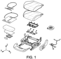
- the seat of such a seat also comprises a suspension system typically with spring wires, connecting the nose piece to a rear part of the seat structure, but also, a seat padding, typically in expanded polyurethane foam, and a covering covering the foam padding.
- different comfort equipment can be provided, such as a resistive heating pad, a massage system, or even a ventilation system, or even a sliding mechanism that is fixed above the nose piece so as to be able to adjust the advancement of a front part of the cushion, and in relation to a rear portion of the cushion, fixed.
- a design of a seat according to the figure 1 requires assembling, typically manually, a large number of components on the final assembly site of the vehicle, which may not be economically optimal when the assembly site has high cost labor.
- Modern seats can be equipped with additional functions, such as a heating, massage, or ventilation function.
- This equipment is integrated in the factory during the manufacture of the seat, then topped with the cushions with their quilting and coverings. The seat thus assembled is then fixed to the floor of the vehicle.
- the design of the seats known from the state of the art does not does not allow the seat to be dismantled within the vehicle itself, that is to say without removing the seat from the floor of the vehicle, in order to improve the seat by adding an additional heating, ventilation, or massage.
- the addition of such equipment would require removing the seat from the vehicle to remove the coverings and the padding, this removal being necessary for such an addition.
- a composite nose piece of the base is articulated to a base body, around a transverse axis of the seat, the nose piece comprising a set of hooks which are fixed on the front tube.
- the possible rotation between the nose piece and the base contributes to the dissipation of energy during impact, and favorably supports the hips in order to avoid underwatering.
- the attachment of the module to the seat structure can be improved.
- Such a modular seat cushion according to the present disclosure offers the following advantages, compared to the state of the art known to the Applicant, and in particular:
- a simplified assembly of the modular seat cushion on the structure with in particular a kinematics for assembling and locking the modular seat cushion on the seat structure in only two fixing points, consisting respectively of the front tube and the rear tube of the structure.
- Such assembly and locking kinematics are fast and intuitive for operators offering short cycle times.
- Such assembly and locking kinematics comprising in /A/ a prior nesting of the rear tube in the first housing of the rear mechanical interface (namely before locking of the front tube by the locking system of the mechanical interface front) also limits the effort of handling and carrying the modular seat cushion by the operator:
- Such a design advantageously reduces the risk of musculoskeletal disorders.
- Such modular seat cushion assembly and locking kinematics can also allow easy maintenance, and in particular rapid dismantling of the modular seat cushion, in particular without dismantling the seat structure of a floor of the vehicle.
- the first side padding and the second side padding are independent and removable elements relative to the central portion of the padding.
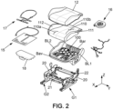
- the present disclosure relates to a modular seat cushion 1, configured to be fixed to a seat structure 2 having a seat structure comprising two side flanges 20 braced by a transverse front tube 21 and a rear tube 22, transverse.
- the base 10 is a body, preferably thin, which extends from a rear edge Bar to a front edge Bav typically in direction X, and from a first side edge BL1 to a second side edge BL2 in the transverse direction.
- the base can typically be a body molded in one piece, typically by injection molding techniques.
- the padding 11 rests on the upper surface of the base.
- the profile of the body seen in a section passing through a plane especially to the front edge of the body. Such a rising profile ensures support for the hips of the user seated in the seat, limiting the risk of submarining in the event of a frontal impact.
- the profile of the body seen in a section passing through a plane YZ, can be concave, the first lateral edge BL1, and the second lateral edge BL2 being raised in the direction Z, relative to a central portion of the body between the two edges lateral BI1, BI2.
- the base 10 may include a suspension system 100 typically provided on a central portion of the base 10 between the first side edge BL1 and the second side edge BL2 of the body.
- the suspension system 100 is obtained during injection molding, and can consist of an elastic perforated portion 101 of the base, typically extending, over a central portion, between the first side edge BL1 and the second side edge BLI2 to proximity of the rear edge Bar in comparison to the front edge Bav, namely that the suspension system is located, in particular in the direction X, closer to the rear edge Barque of the front edge Bav.
- the base 10 may comprise a suspension system 100 which typically extends over a central portion of the base between a first side edge and a second side edge of the body.
- the first rear housing LG1 has the function of authorizing in /A/, the insertion of the rear tube 22, and of authorizing the pivoting of the modular seat cushion around the rear tube 22, in a safe manner, while this rear tube 22 is fitted into the first housing LG1.
- the design of the first housing LG1 prevents escape from the rear tube 22 which is blocked in the first housing LG1.
- the first housing LG1 can typically be a U-shaped (or C-shaped) housing having a bottom wall and side walls
- the second housing LG2 can typically be a U-shaped (or C-shaped) housing having a bottom wall and side walls.
- other forms of housing can be envisaged for the first housing LG1 and/or the second housing LG2, for example housings with polygonal sections, for example rectangular, pentagonal or others.
- the first U-shaped housing, marked LG1 can open towards the rear of the base 10 in a rearward direction oriented from the front portion towards the rear portion of the base 10.
- the first U-shaped housing, marked LG1 has an upper side wall and an opposing lower side wall, as well as a bottom wall.
- Such a first housing, in particular U-shaped is configured so as to ensure stable holding of the rear tube 22 against the bottom wall when the base 10 exerts a force on the rear tube 22 directed in the rear direction, the rear tube 22 then blocked in a direction perpendicular to the base between the lower and upper side walls.
- the first housing in particular U-shaped LG1
- the second housing in particular U-shaped LG2
- the first housing can open towards the rear, substantially in the direction of a mean plane PM, in a direction slightly inclined relative to the mean plane of the base 2, typically + or - 30°.
- the second housing in particular U-shaped LG2, can open towards the bottom typically in a direction perpendicular to the average plane PM of the base, or slightly inclined relative to this plane typically by + or - 30°.
- the first housing LG1 in particular U-shaped, can comprise a first direction of insertion D1 for the rear tube 22, extending in the direction of a mean plane PM, in a direction slightly inclined relative to the mean plane of the base 2, typically + or - 30° and the second housing LG2 in particular U-shaped may comprise a second direction of insertion D2 for the front tube 21, following a direction perpendicular to the mean plane PM of the base, or slightly inclined relative to to this direction typically + or - 30°.
- the first direction of insertion D1 and the second direction of insertion D2 are inclined relative to each other by an angle typically between 45° and 90°.
- the first housing LG 1, in particular U-shaped can be formed by a continuous groove in the transverse direction, or else formed by several elements, in particular U-shaped, discreetly spaced in the transverse direction Y.
- the second housing LG2, in particular U-shaped can be formed by a groove continuous in the transverse direction Y, or else formed by several elements in particular in a U, discreetly spaced in the transverse direction Y.
- the different walls of the U in particular the side walls and the bottom wall
- the padding 11 provides the softness and comfort of the seat, and can be in a material such as expanded polyurethane foam.
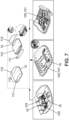
- the padding 11, including the central portion 110, the first side padding 111 and the second side padding 112 can be formed by a single piece element, and in particular as illustrated in the top view, to the left of the figure 7 .
- the first side padding 111 and/or the second side padding 112 can be independent and removable elements relative to the central portion 110 of the padding 11. In the event of maintenance; it is thus possible to change only the worn element of the padding while retaining the others: for example, it is possible to change the first side padding 111 and/or the second side padding 112 which tend to wear out more quickly, by retaining the central portion 110.
- the central portion of the padding may also include a rear portion 110b, fixed, and a front portion 110a, mobile.
- the rear portion 110b is fixed on the base 10 while a slide system 18 can be provided between the base 10 and the front portion 110a. This slide system makes it possible to move the front portion 110a of the central portion 110 forward or backward relative to the rear portion 110b.
- the base 10 can be a body obtained by injection molding; said front mechanical interface 14 and said rear mechanical interface 13 can be arranged respectively on the front and rear part of the base 10, and be in one piece with the body, said rear and front mechanical interfaces 13,14 being obtained during the injection molding.
- the front mechanical interface 14 and/or the rear mechanical interface 13 can be formed by elements attached to the body of the base 10.
- the installation and fixing of the modular seat cushion to the seat structure according to the present disclosure is quick, safe and preferably carried out without tools, in particular for steps /A/ and /B/.
- the mechanical locking of the front tube 21 may require a user operation additional to the (simple) pivoting in /B/, for example, a movement of a latch of the locking system as a non-limiting example , or the installation of a retaining member, removable from the front mechanical interface, such as a retaining tab.
- the locking system can be configured to ensure locking automatically during pivoting in /B/.
- the locking system can be elastically deformable, configured to authorize elastic locking so that the locking of the front tube 21 in the second housing LG2 of the front mechanical interface is obtained, at the end of the stroke during of the pivoting in /B/ of the modular cushion around the rear tube 22, by elastic deformation of the locking system.
- the second housing, in particular U-shaped, LG2 can be an elastically deformable groove having a groove inlet of dimension less than the diameter of the front tube 21, the groove having an adjusted interior section to the section of the front tube 21 of dimension greater than the throat inlet.
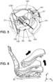
- said front mechanical interface 14 may comprise a locking member 140, articulated by a flexible hinge 141, at an end proximal to the body of the base with respect to the second housing and having a locking tooth 142 at its distal end, as well as a cam 143 secured to the locking member 140.
- Said locking member 140 is configured to move from an unlocked position P1, leaving the second housing LG2 open, illustrated on the right in the figure 5 , up to a locked position P2 closing the second housing LG2, illustrated on the left in the figure 5 .
- step /B/ the front tube 21 engages with the cam 143, when it is inserted into the second housing, causing the locking member 140 to move around the hinge 141 from the unlocked position P1 until to the locked position P2: during such a movement, said locking member 140 deforms elastically passing a counter-tooth 144 of the mechanical interface 14, secured to the base and up to the locked position P2 for which said locking member 140 relaxes at least partially in a position where the locking tooth 142 and the counter-tooth 144 cooperate with each other to prevent the unlocking of the locking member 140 in a position where the locking member 140 maintains prisoner said front tube 21 in the second housing LG2.
- the locking member 140 may have an L shape, the hinge 141 provided at one end of the L, the locking tooth at an opposite end of the L.
- the cam may comprise an arm which extends generally parallel to the aid lower part of the L and so that the front tube 21 is housed between the cam and the lower wing of the L when driving the cam.
- the present disclosure also relates to a seat assembly comprising a modular seat cushion 1 and a seat structure 2 having a seat structure comprising two side flanges 30 braced by a transverse front tube 21 and a rear tube 22 , transversal, or even a folder structure.
- mechanical locking may require a user operation additional to simple pivoting, for example, moving a latch of the locking system, or even the installation of a retaining member.
- the locking system can be configured to ensure locking automatically when pivoting in /B/.
- the locking system can be elastically deformable, configured to authorize elastic locking so that the locking of the front tube 21 in the second housing LG2 of the front mechanical interface is obtained, at the end of the stroke during of the pivoting in /B/ of the modular cushion around the rear tube 22, by elastic deformation of the locking system.
- the assembly between the modular cushion and the seat structure can also allow rapid disassembly, and advantageously disassembly of the modular cushion without dismantling the seat structure on the floor of the vehicle.
- Such removal of the modular cushion without dismantling the seat structure, allows easy maintenance of the cushion, by replacement of one or more worn elements, for example replacement of one or more linings, by substitution of a new modular cushion, or even enhanced with comfort equipment, such as the resistive heating pad, the ventilation system, or the massage system, or the system comprising one or more haptic exciters.
Landscapes
- Engineering & Computer Science (AREA)
- Aviation & Aerospace Engineering (AREA)
- Transportation (AREA)
- Mechanical Engineering (AREA)
- Seats For Vehicles (AREA)
Applications Claiming Priority (1)
| Application Number | Priority Date | Filing Date | Title |
|---|---|---|---|
| FR2300038A FR3144574B1 (fr) | 2023-01-03 | 2023-01-03 | Coussin modulaire d’assise, et ensemble de siège comprenant un tel coussin |
Publications (1)
| Publication Number | Publication Date |
|---|---|
| EP4400363A1 true EP4400363A1 (de) | 2024-07-17 |
Family
ID=86942199
Family Applications (1)
| Application Number | Title | Priority Date | Filing Date |
|---|---|---|---|
| EP23307094.5A Pending EP4400363A1 (de) | 2023-01-03 | 2023-11-30 | Modulares sitzkissen und sitzanordnung mit einem solchen kissen |
Country Status (5)
| Country | Link |
|---|---|
| US (1) | US20240215732A1 (de) |
| EP (1) | EP4400363A1 (de) |
| JP (1) | JP2024096526A (de) |
| CN (1) | CN118288872A (de) |
| FR (1) | FR3144574B1 (de) |
Families Citing this family (1)
| Publication number | Priority date | Publication date | Assignee | Title |
|---|---|---|---|---|
| EP4530127A1 (de) * | 2023-09-29 | 2025-04-02 | FAURECIA Sièges d'Automobile | Modulares sitzkissen und sitzanordnung mit einem solchen kissen |
Citations (3)
| Publication number | Priority date | Publication date | Assignee | Title |
|---|---|---|---|---|
| US20170036577A1 (en) * | 2015-08-03 | 2017-02-09 | Ford Global Technologies, Llc | Seat cushion module for a vehicle seating assembly |
| US9796310B1 (en) | 2016-07-28 | 2017-10-24 | Ford Global Technologies, Llc | Composite one-piece cushion nose |
| US20180093598A1 (en) * | 2016-10-03 | 2018-04-05 | Toyota Jidosha Kabushiki Kaisha | Vehicle seat |
Family Cites Families (5)
| Publication number | Priority date | Publication date | Assignee | Title |
|---|---|---|---|---|
| US4065182A (en) * | 1976-08-30 | 1977-12-27 | General Motors Corporation | Cushion retention for a vehicle seat |
| US5485976A (en) * | 1994-01-12 | 1996-01-23 | Weber Aircraft, Inc. | Plastic bottom diaphragm for aircraft seat |
| US8782835B2 (en) * | 2012-03-20 | 2014-07-22 | Be Aerospace, Inc. | Seat cushion with integrated seat frame attachment structure |
| US9764844B2 (en) * | 2015-04-13 | 2017-09-19 | Encore Seats, Inc. | Aircraft seating assembly |
| DE102015114677A1 (de) * | 2015-09-02 | 2017-03-02 | Recaro Aircraft Seating Gmbh & Co. Kg | Flugzeugsitzvorrichtung |
-
2023
- 2023-01-03 FR FR2300038A patent/FR3144574B1/fr active Active
- 2023-11-30 EP EP23307094.5A patent/EP4400363A1/de active Pending
- 2023-12-27 JP JP2023221505A patent/JP2024096526A/ja active Pending
- 2023-12-29 US US18/399,968 patent/US20240215732A1/en active Pending
-
2024
- 2024-01-03 CN CN202410009183.7A patent/CN118288872A/zh active Pending
Patent Citations (3)
| Publication number | Priority date | Publication date | Assignee | Title |
|---|---|---|---|---|
| US20170036577A1 (en) * | 2015-08-03 | 2017-02-09 | Ford Global Technologies, Llc | Seat cushion module for a vehicle seating assembly |
| US9796310B1 (en) | 2016-07-28 | 2017-10-24 | Ford Global Technologies, Llc | Composite one-piece cushion nose |
| US20180093598A1 (en) * | 2016-10-03 | 2018-04-05 | Toyota Jidosha Kabushiki Kaisha | Vehicle seat |
Also Published As
| Publication number | Publication date |
|---|---|
| FR3144574B1 (fr) | 2025-01-03 |
| CN118288872A (zh) | 2024-07-05 |
| JP2024096526A (ja) | 2024-07-16 |
| US20240215732A1 (en) | 2024-07-04 |
| FR3144574A1 (fr) | 2024-07-05 |
Similar Documents
| Publication | Publication Date | Title |
|---|---|---|
| EP4011695B1 (de) | Rückenlehne eines fahrzeugsitzes | |
| EP4011693B1 (de) | Rückenlehne eines fahrzeugsitzes | |
| EP3310604B1 (de) | Batterieträgeranordnung für ein hybridfahrzeug | |
| EP4029730B1 (de) | Rückenlehne eines fahrzeugsitzes | |
| EP4400363A1 (de) | Modulares sitzkissen und sitzanordnung mit einem solchen kissen | |
| EP1927500B1 (de) | Fahrzeuginnenraum, Sitzgestell und Montageverfahren | |
| FR2969053A1 (fr) | Ensemble de glissieres pour siege de vehicule et siege de vehicule comportant un tel ensemble de glissieres. | |
| FR2883810A1 (fr) | Ensemble de glissieres et siege comportant un tel ensemble de glissieres | |
| WO2005051704A1 (fr) | Siege reglable pour vehicule automobile, et vehicule automobile equipe d'un tel siege. | |
| FR3079215A1 (fr) | Carenage avant d'un mat d'aeronef comprenant une coiffe mobile et aeronef equipe dudit carenage avant | |
| EP4397536B1 (de) | Modulares sitzkissen mit modularem seitenquerglied und sitzanordnung mit solch einem kissen und solch einem seitenquerglied | |
| FR3153575A1 (fr) | Dossier de siège de véhicule et siège comprenant un tel dossier | |
| FR3156080A1 (fr) | Support de garniture | |
| EP3738832B1 (de) | Innenhalterung eines auskuppelbaren objekts für kraftfahrzeug | |
| EP4530127A1 (de) | Modulares sitzkissen und sitzanordnung mit einem solchen kissen | |
| FR3147155A1 (fr) | Support de garniture d’assise, comprenant un élément plastique ajouré | |
| EP2616269B1 (de) | Sitz für ein kraftfahrzeug | |
| FR3122127A1 (fr) | Dispositif de blocage en rotation de l’assise d’un siège de véhicule | |
| EP1674335B1 (de) | Kraftfahrzeugsitz mit Schalenrückenlehne | |
| EP3753788B1 (de) | Innenschale einer mittelkonsole eines kraftfahrzeugs | |
| EP1518747B1 (de) | Fahrzeugsitz mit einem, zwischen einer Erwachsenen- und einer Kindstellung umklappbaren Kissen | |
| FR2954242A1 (fr) | Dossier de siege d’automobile comportant un accoudoir escamotable. | |
| EP1396379A1 (de) | Klappsitz mit Stützanschlägen für die Benutzungsstellung des Sitzes | |
| EP1726487B1 (de) | Gleitanordnung für einen Fahrzeuginnenraum | |
| EP1541408B1 (de) | Fahrzeugsitz mit einem schwenkbaren Kissen, welches zur Herstellung eines Stütz- oder Halteelementes geeignet ist. |
Legal Events
| Date | Code | Title | Description |
|---|---|---|---|
| PUAI | Public reference made under article 153(3) epc to a published international application that has entered the european phase |
Free format text: ORIGINAL CODE: 0009012 |
|
| STAA | Information on the status of an ep patent application or granted ep patent |
Free format text: STATUS: THE APPLICATION HAS BEEN PUBLISHED |
|
| AK | Designated contracting states |
Kind code of ref document: A1 Designated state(s): AL AT BE BG CH CY CZ DE DK EE ES FI FR GB GR HR HU IE IS IT LI LT LU LV MC ME MK MT NL NO PL PT RO RS SE SI SK SM TR |
|
| STAA | Information on the status of an ep patent application or granted ep patent |
Free format text: STATUS: REQUEST FOR EXAMINATION WAS MADE |
|
| 17P | Request for examination filed |
Effective date: 20250114 |