EP4400634A1 - Procédé de production d'une feuille de cuivre par dépôt électrolytique de cuivre - Google Patents
Procédé de production d'une feuille de cuivre par dépôt électrolytique de cuivre Download PDFInfo
- Publication number
- EP4400634A1 EP4400634A1 EP23151521.4A EP23151521A EP4400634A1 EP 4400634 A1 EP4400634 A1 EP 4400634A1 EP 23151521 A EP23151521 A EP 23151521A EP 4400634 A1 EP4400634 A1 EP 4400634A1
- Authority
- EP
- European Patent Office
- Prior art keywords
- copper
- electrolyte solution
- process according
- cathode
- ions
- Prior art date
- Legal status (The legal status is an assumption and is not a legal conclusion. Google has not performed a legal analysis and makes no representation as to the accuracy of the status listed.)
- Withdrawn
Links
Images
Classifications
-
- C—CHEMISTRY; METALLURGY
- C25—ELECTROLYTIC OR ELECTROPHORETIC PROCESSES; APPARATUS THEREFOR
- C25D—PROCESSES FOR THE ELECTROLYTIC OR ELECTROPHORETIC PRODUCTION OF COATINGS; ELECTROFORMING; APPARATUS THEREFOR
- C25D1/00—Electroforming
- C25D1/04—Wires; Strips; Foils
-
- C—CHEMISTRY; METALLURGY
- C25—ELECTROLYTIC OR ELECTROPHORETIC PROCESSES; APPARATUS THEREFOR
- C25D—PROCESSES FOR THE ELECTROLYTIC OR ELECTROPHORETIC PRODUCTION OF COATINGS; ELECTROFORMING; APPARATUS THEREFOR
- C25D1/00—Electroforming
-
- C—CHEMISTRY; METALLURGY
- C25—ELECTROLYTIC OR ELECTROPHORETIC PROCESSES; APPARATUS THEREFOR
- C25D—PROCESSES FOR THE ELECTROLYTIC OR ELECTROPHORETIC PRODUCTION OF COATINGS; ELECTROFORMING; APPARATUS THEREFOR
- C25D1/00—Electroforming
- C25D1/20—Separation of the formed objects from the electrodes with no destruction of said electrodes
-
- C—CHEMISTRY; METALLURGY
- C25—ELECTROLYTIC OR ELECTROPHORETIC PROCESSES; APPARATUS THEREFOR
- C25D—PROCESSES FOR THE ELECTROLYTIC OR ELECTROPHORETIC PRODUCTION OF COATINGS; ELECTROFORMING; APPARATUS THEREFOR
- C25D17/00—Constructional parts, or assemblies thereof, of cells for electrolytic coating
- C25D17/10—Electrodes, e.g. composition, counter electrode
- C25D17/12—Shape or form
-
- C—CHEMISTRY; METALLURGY
- C25—ELECTROLYTIC OR ELECTROPHORETIC PROCESSES; APPARATUS THEREFOR
- C25D—PROCESSES FOR THE ELECTROLYTIC OR ELECTROPHORETIC PRODUCTION OF COATINGS; ELECTROFORMING; APPARATUS THEREFOR
- C25D21/00—Processes for servicing or operating cells for electrolytic coating
- C25D21/12—Process control or regulation
- C25D21/14—Controlled addition of electrolyte components
-
- C—CHEMISTRY; METALLURGY
- C25—ELECTROLYTIC OR ELECTROPHORETIC PROCESSES; APPARATUS THEREFOR
- C25D—PROCESSES FOR THE ELECTROLYTIC OR ELECTROPHORETIC PRODUCTION OF COATINGS; ELECTROFORMING; APPARATUS THEREFOR
- C25D3/00—Electroplating: Baths therefor
- C25D3/02—Electroplating: Baths therefor from solutions
- C25D3/38—Electroplating: Baths therefor from solutions of copper
Definitions
- the present invention relates to a process for producing copper foil by electrolytic deposition of copper metal on a rotating drum cathode and, in particular, to the means for dissolving the copper to be deposited in the process.
- the electrolyte solution typically contains copper sulfate, sulfuric acid, chloride and organic compounds.
- Current densities are in the range of 50 to 80 A/dm 2 and treatment times around 60 seconds at 50 °C.
- Drum speeds vary between 7 m/min (for copper foils for lithium batteries) and 25 m/min (for copper foils for printed circuit boards). Copper foils manufactured in this way can have lengths of several kilometers.
- titanium anodes coated with MOX are typically used as insoluble anodes.
- oxygen is created at the anode surface and turns the electrolyte into a milky blue solution. The oxygen bubbles can lead to plating defects and the damage of the anodes.
- the copper deposited from the electrolyte solution onto the drum cathode needs to be replaced continuously so as to keep the copper concentration in the electrolyte solution constant.
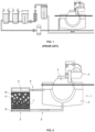
- Fig. 1 a copper dissolution tank as shown in Fig. 1 .
- the two tanks on the lefthand side are the copper dissolving tanks (sometimes up to 250,000 I electrolyte), where the solution is heated up to 80 °C and air is blown into the electrolyte to enable/enhance the dissolution of copper metal.
- the third tank (approx. 5,000 I) from the left (right to the two solution tanks) takes care of the destroyed organics.
- active carbon is mixed into the solution.
- the active carbon then absorbs the organic compounds and is subsequently removed by filtration.
- the spent active carbon must then be disposed of.
- the electrolyte is stored in another tank.
- the electrolyte is cooled down to about 50 °C and the missing organic electrolyte compounds are added before the solution is transferred back into the plating tank of an apparatus containing the drum cathode and the device to peel off the copper foil.
- WO 95/18251 A1 describes a process and device for the electrolytic deposition of metallic layers wherein insoluble anodes are used for the electrolytic deposition of uniform metallic layers having determined physico-mechanical properties, in particular copper layers.
- compounds of a redox system comprising e.g. Fe 2+ /Fe 3+ , are added to the deposition solution and react at the insoluble anodes during deposition.
- the resulting compounds draw new metal ions out of part of a reservoir that contains the metal to be deposited in order to replace the metal ions deposited from the solution.
- the additive compounds are not destroyed (to a larger extent).
- WO 01/68953 A1 describes a method and device for the regulation of the concentration of metal ions in an electrolyte for the electrolytic deposition of metals, the electrolyte containing additional substances of an electrochemically reversible redox system.
- the electrolyte is passed through an auxiliary cell, comprising an insoluble auxiliary anode and at least one auxiliary cathode, between which a flow of current is generated by application of a voltage. Excess amounts of the oxidized material from the redox system are thus reduced at the auxiliary cathode and the formation of ions of the metal to be deposited is avoided.
- pieces of the metal to be deposited are used as the auxiliary cathode.
- the above conventional method to produce copper foil is disadvantageous in that it consumes large amounts of energy, it consumes large amounts of active carbon which, when spent, needs to be disposed of as industrial waste, and the device is relatively complex and, thus, requires significant maintenance effort.
- the invention relates to a continuous process for producing copper foil by electrolytic deposition of copper metal on a rotating drum cathode and, in particular, to the means for dissolving the copper to be deposited in the process; the process consumes low amounts of energy and no significant amounts of active carbon and can be carried out by means of a relatively simple device requiring reduced maintenance effort.
- copper is electrolytically deposited on a rotating drum cathode, which is partially immersed in an electrolyte solution contained in a plating tank; the copper layer deposited on the drum cathode is peeled off the part of the drum cathode that is not immersed in the electrolyte solution to obtain the copper foil; an insoluble anode is used as counter-electrode to the drum cathode; the electrolyte solution contains copper ions, organic additives and an Fe 2+ /Fe 3+ redox system; the concentration of copper ions in the electrolyte solution is maintained constant by passing the electrolyte solution through a copper dissolution unit; in the copper dissolution unit, the electrolyte solution is in contact with an auxiliary anode and an auxiliary cathode; copper metal and an oxygen-containing gas are introduced into the copper dissolution unit; the auxiliary anode is in contact with the copper metal; the oxygen-containing gas is introduced such that bubbles thereof contact the surface of the copper metal; the copper
- the copper metal may be introduced into the dissolution unit in the form of copper clippings.
- the copper metal e.g. clippings
- the copper metal may be placed in a basket made of an inert metal such as titanium.
- the basket then functions as the auxiliary anode.
- the copper metal continuously dissolves into the electrolyte solution by being oxidized by the Fe 3+ component of the Fe 2+ /Fe 3+ redox system. This dissolution process is described by the following chemical equation: Cu 0 + 2 Fe 3+ ⁇ Cu 2+ + 2 Fe 2+
- the Fe 3+ is generated predominantly by oxidation of Fe 2+ at the insoluble anode used as counter-electrode to the drum cathode in the plating tank.
- An oxygen-containing gas e.g. air
- An oxygen-containing gas is introduced into the dissolution unit such that bubbles thereof contact the surface of the copper metal, for example by bubbling the oxygen-containing gas, into the dissolution unit at a location beneath a basket containing the copper metal in the form of copper clippings to generate moderate gas agitation around the surface of copper metal.
- the copper metal (e.g. copper clippings) in the dissolution unit is in electrical contact with the auxiliary anode.
- the auxiliary cathode i.e. a metallic device (e.g., mesh), which has a positive potential; this potential has to be lower than the positive potential for copper deposition within the dissolving tank.
- the copper metal at a negative potential and the auxiliary cathode with a positive potential will eliminate any existing Fe 3+ ions. The current efficiency at the drum cathode will thus remain close to 100 %.
- the copper concentration in the electrolyte solution can be effectively controlled and thereby kept within a narrow and high concentration range required for efficient and constant deposition of copper on the drum cathode by (i) controlling the potential applied to the auxiliary anode (i.e. the voltage between the auxiliary anode and the auxiliary cathode) and (ii), to a lesser extent, by controlling the intensity of the gas agitation.
- the electrolyte solution contains an Fe 2+ /Fe 3+ redox system, i.e. a combination of ferrous and ferric compounds.
- Fe 3+ ions are generated predominantly by oxidation of Fe 2+ at the insoluble anode and, after they are transferred to the dissolution unit, then act as an oxidant to oxidize copper metal to Cu 2+ and thereby dissolve the copper metal into the electrolyte solution.
- This use of an Fe 2+ /Fe 3+ redox system as a means to dissolve copper metal in the large amounts required in a process for producing copper foil and in a well-controlled manner has the following advantages compared to conventional processes for producing copper foil: Firstly, the oxidization of Fe 2+ to Fe 3+ at the insoluble anode competes with, and thus suppresses oxygen evolution and organic additive burning at the anode. Thus, consumption of organic additives (and the ensuing generation of contaminating decomposition products) is only due to the copper deposition processes at the drum cathode. Thereby, the total organic content (TOC) of the electrolyte solution remains low and extends the plating bath lifetime. Additionally, due to avoiding oxygen development at the anode, the lifetime of the anode is greatly increased.
- TOC total organic content
- the addition of Fe 2+ /Fe 3+ lowers the required voltage to achieve a current density of 50 A/dm 2 by more than 25 %, as no oxygen bubbles are created at the insoluble anode.
- 20 g/l of Fe 2+ was added to a plating solution containing 60 g/l of Cu 2+ , 150 g/l of H 2 SO 4 , 40 mg/l of Cl - , 3 ml/l of conventional brightener, 11 ml/l of conventional carrier, and 5 ml/l of conventional levelling agent, at 50 °C with a cell current of 40 A; the cell voltage dropped after Fe 2+ addition from 3.2 V down to 2.4 V.
- an aqueous acidic copper plating bath is preferably used as the electrolyte solution.
- Such baths are known from the prior art, for example from EP 0 690 934 A1 .
- the basic composition of the electrolyte solution bath can vary within relatively large boundaries.
- an aqueous solution of the following composition is used: copper sulfate (CuSOa ⁇ 5 H 2 O): 20-250 g/l, preferably 80-140g/l or 180-220g/l; conc.
- sulfuric acid 50-350 g/l, preferably 180-280 g/l or 50-90 g/l; iron (II) sulfate (FeSOa ⁇ 7 H 2 O): 0.1-50 g/l, preferably 5-15 g/l; chloride ions (added for example as NaCl): 0.01-0.18 g/l, preferably 0.03-0.1 g/l.
- iron sulfate instead of copper sulfate, other copper salts can be used at least in part.
- the sulfuric acid can be partly or wholly replaced by fluoroboric acid, methanesulfonic acid or other acids. That is, the electrolyte solution can be free or substantially free of sulfuric acid and/or sulfate salts. In particular, the electrolyte solution can contain methanesulfonic acid and the iron and/or copper salts thereof.
- the chloride ions are added as alkali chlorides, for example sodium chloride or in the form of hydrochloric acid.
- the addition of sodium chloride can be dispensed with wholly or partly if halogen ions are already contained in the supplements.
- the electrolyte solution contains an Fe 2+ /Fe 3+ redox system.
- the Fe 2+ /Fe 3+ redox system can be formed from iron (II) sulfate heptahydrate. It is particularly suited to regenerating copper ions in aqueous, acidic copper baths.
- iron salts for example the iron salt of methanesulfonic acid and iron (III) sulfate nonahydrate, can also be used as long as the salts contain no biologically non-degradable (hard) complexing agents in the compound since the latter present problems during waste disposal (e.g. iron ammonium alum).
- the organic additives contained in the electrolyte solution comprise, in particular, at last one brightener, at least one levelling agent and at least one carrier.
- the electrolyte solution generally contains copper ions (preferably, Cu 2+ ions), Fe 2+ ions, an acid, chloride ions, a brightener, a levelling agent and a carrier.
- the brightener can be an organic sulfur-containing compound; this is preferably selected from one or more compounds selected from the group consisting of organic thiol, sulfide, disulfide and polysulfide compounds, preferably selected from the group consisting of 3-(benzthiazolyl-2-thio)-propylsulfonic acid, 3-mercaptopropane-1-sulfonic acid, ethylendithiodipropylsulfonic acid, bis-(p-sulfophenyl)-disulfide, bis-(w-sulfobutyl)-disulfide, bis-(w-sulfohydroxypropyl)-disulfide, bis-( ⁇ -sulfopropyl)-disulfide, bis-( ⁇ -sulfopropyl)-sulfide, methyl-(w-sulfopropyl)-disulfide, methyl-( ⁇ -sulfopropyl
- the levelling agent can be a nitrogen-containing compound; this is preferably selected from one or more compounds selected from the group consisting of a ureylene polymer, polyethyleneimine, alkoxylated polyethyleneimine, alkoxylated lactams and polymers thereof, diethylenetriamine and hexamethylenetetramine, polyethylenimine bearing peptides, polyethylenimine bearing amino acids, polyvinylalcohol bearing peptides, polyvinyl alcohol bearing amino acids, polyalkyleneglycol bearing peptides, polyalkyleneglycol bearing amino acids, aminoalkylene bearing pyrroles and aminoalkylene bearing pyridines, organic dyes such as Janus Green B, Bismarck Brown Y and Acid Violet 7, sulfur containing amino acids such as cysteine, and phenazinium salts.
- the levelling agent is added to the electrolyte solution (in total) in amounts of 0.5 mg/l to 400 mg/l, preferably 0.1 mg/l to 100
- the carrier can be an oxygen-containing compound; this is preferably selected from one or more compounds selected from the group consisting of polyvinylalcohol, carboxymethylcellulose, polyethylenglycol, polypropylenglycol, stearic acid polyglycol ester, alkoxylated naphtoles, oleic acid polyglycol ester, stearylalcoholpolyglycol ether, nonylphenolpolyglycol ether, octanolpolyalkylenglycol ether, octanediol-bis-(polyalkylenglycol ether), poly(ethylenglycol-ran-propylenglycol), poly(ethylenglycol)-block-poly(propylenglycol)-block-poly(ethylenglycol), and poly(propylenglycol)-block-poly(ethylenglycol)-block-poly(propylenglycol).
- the inventive process can be conducted in an apparatus, comprising a plating device 1 having a plating tank with the electrolyte solution 4 with a rotating drum cathode 3 , a peeling device 2 and a Cu dissolution unit 5 , as shown in Fig. 2 .
- a plating device 1 having a plating tank with the electrolyte solution 4 with a rotating drum cathode 3 , a peeling device 2 and a Cu dissolution unit 5 , as shown in Fig. 2 .
- copper is electrolytically deposited on a rotating drum cathode 3 , which is partially immersed in an electrolyte solution 4 contained in a plating tank.
- the drum cathode typically has a diameter of 0.5 to 4.0 m, preferably 1.5 to 2.5 m.
- the drum cathode typically has a width of 0.5 to 3.0 m, preferably 1.0 to 2.0 m.
- the current density at the drum cathode is typically 20 to 100 A/dm 2 , preferably 30 to 80 A/sm 2 , more preferably 40 to 70 A/dm 2 .
- the rotation speed of the drum cathode is typically 1 to 15 m/min, preferably 5 to 10 m/min.
- the amount of copper deposited on the drum cathode is typically 10 to 50 kg/min, preferably 30 to 40 kg/min.
- the thickness of the copper foil produced by the process according to the invention is typically 2 to 30 ⁇ m, preferably 5 to 20 ⁇ m, more preferably 7 to 12 ⁇ m.
- an insoluble anode is used as counter-electrode to the drum cathode.
- the current density at the insoluble anode is typically > 20 A/dm 2 .
- copper is electrolytically deposited on a rotating drum cathode, typically at a temperature of 15 to 70°C, preferably 25 to 60 °C, more preferably 40 to 50°C.
- the concentration of copper ions in the electrolyte solution is maintained constant by passing the electrolyte solution through a copper dissolution unit.
- the concentration of copper ions in the electrolyte solution present in the plating tank is typically 80 to 90 g/l.
- the concentration of Fe 3+ ions in the electrolyte solution present in the plating tank is typically ⁇ 5 g/l, preferably ⁇ 5 g/l.
- a part of the electrolyte solution present in the plating tank is continuously or periodically withdrawn from the plating tank and transferred to the dissolution unit.
- this is done such that the part of the electrolyte solution withdrawn according to Fig. 2 from the plating tank is introduced into the Cu (copper) dissolution unit 2 at a location that is closer to the auxiliary cathode as a cathode mesh 6 than to the auxiliary anode as an anode mesh 7 so that the withdrawn part comes into contact with the auxiliary cathode first.
- the part of the electrolyte solution withdrawn from the plating tank contains Fe 3+ ions at a relatively high concentration (Fe 3+ rich solution 8 ) and Fe 2+ ions at a relatively low concentration.
- Fe 3+ rich solution 8 The part of the electrolyte solution withdrawn from the plating tank contains Fe 3+ ions at a relatively high concentration (Fe 3+ rich solution 8 ) and Fe 2+ ions at a relatively low concentration.
- the Fe 3+ plus ions contribute to the oxidation of copper metal (which thereby dissolves) and are thereby reduced to Fe 2+ ions. Therefore, after it has passed through the Cu dissolution unit, the electrolyte solution contains Fe 3+ ions at a relatively low concentration and Fe 2+ ions at a relatively high concentration (Fe 2+ rich solution 9 ).
- the electrolyte solution 4 is in contact with an auxiliary anode 7 and an auxiliary cathode 6.
- a voltage is applied between the auxiliary anode and the auxiliary cathode. This voltage is typically 1 to 9 V, preferably 2 to 4 V.
- the auxiliary anode is in contact with the copper metal 10.
- the application of this voltage and the copper metal being in contact with the auxiliary anode promotes the dissolution of the copper metal introduced into the dissolution unit such that relatively large amounts of copper can be dissolved per time unit.
- This dissolution is also promoted by the introduction of an oxygen-containing gas into the Cu dissolution unit such that bubbles 11 thereof contact the surface of the copper metal.
- the oxygen-containing gas can be air, preferably is air, more preferably hot air bubbles.
- the air can be introduced by an air blower 12.
- the auxiliary cathode and anode can be made of any kind of conductive and dimensionally stable material.
- the size of the dissolution unit is not particularly limited and can be adapted to the requirements of the process for producing copper foil, especially the amount of copper foil to be produced per time unit.
Landscapes
- Chemical & Material Sciences (AREA)
- Engineering & Computer Science (AREA)
- Chemical Kinetics & Catalysis (AREA)
- Electrochemistry (AREA)
- Materials Engineering (AREA)
- Metallurgy (AREA)
- Organic Chemistry (AREA)
- Automation & Control Theory (AREA)
- Electroplating And Plating Baths Therefor (AREA)
- Electrolytic Production Of Metals (AREA)
Priority Applications (8)
| Application Number | Priority Date | Filing Date | Title |
|---|---|---|---|
| EP23151521.4A EP4400634A1 (fr) | 2023-01-13 | 2023-01-13 | Procédé de production d'une feuille de cuivre par dépôt électrolytique de cuivre |
| PCT/EP2024/050686 WO2024149876A1 (fr) | 2023-01-13 | 2024-01-12 | Procédé de production de feuille de cuivre par dépôt électrolytique de cuivre |
| US19/144,534 US20250354286A1 (en) | 2023-01-13 | 2024-01-12 | Process for producing copper foil by electrolytic deposition of copper |
| JP2025540233A JP2026501464A (ja) | 2023-01-13 | 2024-01-12 | 銅の電解析出によって銅箔を製造する方法 |
| TW113101383A TW202442939A (zh) | 2023-01-13 | 2024-01-12 | 由銅電解沉積製造銅箔的方法 |
| KR1020257022600A KR20250135189A (ko) | 2023-01-13 | 2024-01-12 | 구리의 전해 증착에 의한 구리박 생산 방법 |
| CN202480007528.3A CN120603992A (zh) | 2023-01-13 | 2024-01-12 | 由铜电解沉积制造铜箔的方法 |
| EP24700040.9A EP4649185A1 (fr) | 2023-01-13 | 2024-01-12 | Procédé de production de feuille de cuivre par dépôt électrolytique de cuivre |
Applications Claiming Priority (1)
| Application Number | Priority Date | Filing Date | Title |
|---|---|---|---|
| EP23151521.4A EP4400634A1 (fr) | 2023-01-13 | 2023-01-13 | Procédé de production d'une feuille de cuivre par dépôt électrolytique de cuivre |
Publications (1)
| Publication Number | Publication Date |
|---|---|
| EP4400634A1 true EP4400634A1 (fr) | 2024-07-17 |
Family
ID=84980999
Family Applications (2)
| Application Number | Title | Priority Date | Filing Date |
|---|---|---|---|
| EP23151521.4A Withdrawn EP4400634A1 (fr) | 2023-01-13 | 2023-01-13 | Procédé de production d'une feuille de cuivre par dépôt électrolytique de cuivre |
| EP24700040.9A Withdrawn EP4649185A1 (fr) | 2023-01-13 | 2024-01-12 | Procédé de production de feuille de cuivre par dépôt électrolytique de cuivre |
Family Applications After (1)
| Application Number | Title | Priority Date | Filing Date |
|---|---|---|---|
| EP24700040.9A Withdrawn EP4649185A1 (fr) | 2023-01-13 | 2024-01-12 | Procédé de production de feuille de cuivre par dépôt électrolytique de cuivre |
Country Status (7)
| Country | Link |
|---|---|
| US (1) | US20250354286A1 (fr) |
| EP (2) | EP4400634A1 (fr) |
| JP (1) | JP2026501464A (fr) |
| KR (1) | KR20250135189A (fr) |
| CN (1) | CN120603992A (fr) |
| TW (1) | TW202442939A (fr) |
| WO (1) | WO2024149876A1 (fr) |
Citations (6)
| Publication number | Priority date | Publication date | Assignee | Title |
|---|---|---|---|---|
| WO1995018251A1 (fr) | 1993-12-24 | 1995-07-06 | Atotech Deutschland Gmbh | Procede et dispositif de precipitation par electrolyse de couches metalliques |
| EP0862665B1 (fr) * | 1995-11-21 | 2000-03-15 | ATOTECH Deutschland GmbH | Procede de depot de couches metalliques par voie electrolytique |
| WO2001068953A1 (fr) | 2000-03-17 | 2001-09-20 | Atotech Deutschland Gmbh | Procede et dispositif pour reguler la concentration d'ions metalliques dans un electrolyte, mise en oeuvre dudit procede et utilisation dudit dispositif |
| US20010042686A1 (en) * | 2000-05-18 | 2001-11-22 | Mitsui Mining & Smelting Co., Ltd. | Electrodeposition apparatus for producing electrodeposited copper foil and electrodeposited copper foil produced by use of the apparatus |
| US20020064019A1 (en) | 2000-08-11 | 2002-05-30 | Makoto Dobashi | Cathode electrode material and rotating cathode drum for electrolytic copper foil production using the same |
| US11050050B1 (en) * | 2020-01-22 | 2021-06-29 | Chang Chun Petrochemical Co., Ltd. | Electrolytic copper foil and electrode and lithium-ion cell comprising the same |
-
2023
- 2023-01-13 EP EP23151521.4A patent/EP4400634A1/fr not_active Withdrawn
-
2024
- 2024-01-12 EP EP24700040.9A patent/EP4649185A1/fr not_active Withdrawn
- 2024-01-12 JP JP2025540233A patent/JP2026501464A/ja active Pending
- 2024-01-12 TW TW113101383A patent/TW202442939A/zh unknown
- 2024-01-12 CN CN202480007528.3A patent/CN120603992A/zh active Pending
- 2024-01-12 WO PCT/EP2024/050686 patent/WO2024149876A1/fr not_active Ceased
- 2024-01-12 US US19/144,534 patent/US20250354286A1/en active Pending
- 2024-01-12 KR KR1020257022600A patent/KR20250135189A/ko active Pending
Patent Citations (7)
| Publication number | Priority date | Publication date | Assignee | Title |
|---|---|---|---|---|
| WO1995018251A1 (fr) | 1993-12-24 | 1995-07-06 | Atotech Deutschland Gmbh | Procede et dispositif de precipitation par electrolyse de couches metalliques |
| EP0690934A1 (fr) | 1993-12-24 | 1996-01-10 | ATOTECH Deutschland GmbH | Procede et dispositif de precipitation par electrolyse de couches metalliques |
| EP0862665B1 (fr) * | 1995-11-21 | 2000-03-15 | ATOTECH Deutschland GmbH | Procede de depot de couches metalliques par voie electrolytique |
| WO2001068953A1 (fr) | 2000-03-17 | 2001-09-20 | Atotech Deutschland Gmbh | Procede et dispositif pour reguler la concentration d'ions metalliques dans un electrolyte, mise en oeuvre dudit procede et utilisation dudit dispositif |
| US20010042686A1 (en) * | 2000-05-18 | 2001-11-22 | Mitsui Mining & Smelting Co., Ltd. | Electrodeposition apparatus for producing electrodeposited copper foil and electrodeposited copper foil produced by use of the apparatus |
| US20020064019A1 (en) | 2000-08-11 | 2002-05-30 | Makoto Dobashi | Cathode electrode material and rotating cathode drum for electrolytic copper foil production using the same |
| US11050050B1 (en) * | 2020-01-22 | 2021-06-29 | Chang Chun Petrochemical Co., Ltd. | Electrolytic copper foil and electrode and lithium-ion cell comprising the same |
Also Published As
| Publication number | Publication date |
|---|---|
| WO2024149876A1 (fr) | 2024-07-18 |
| US20250354286A1 (en) | 2025-11-20 |
| CN120603992A (zh) | 2025-09-05 |
| JP2026501464A (ja) | 2026-01-15 |
| EP4649185A1 (fr) | 2025-11-19 |
| KR20250135189A (ko) | 2025-09-12 |
| TW202442939A (zh) | 2024-11-01 |
Similar Documents
| Publication | Publication Date | Title |
|---|---|---|
| TWI448588B (zh) | 連續電鍍銅之方法 | |
| US6129830A (en) | Process for the electrolytic deposition of copper layers | |
| JP5417112B2 (ja) | 金属層の電解析出のための方法 | |
| SG52609A1 (en) | Method of electrolytic precipitation of metallic layers with predetermined physical properties and apparatus for carrying out the method | |
| CN106115991A (zh) | 一种棕化废液处理装置及处理方法 | |
| CN110129799B (zh) | 一种基于硫酸-铁盐体系的退锡废液的回收利用方法 | |
| BR0210829B1 (pt) | processo de regeneraÇço de um banho de revestimento contendo Íons em um estado de alta oxidaÇço durante a deposiÇço de uma camada metÁlica. | |
| KR930010224A (ko) | 지지체 금속표면을 다른 금속으로 치환 도금하는 방법 | |
| US4906340A (en) | Process for electroplating metals | |
| CN1799294B (zh) | 填充微盲孔的方法 | |
| JP4709575B2 (ja) | 銅箔の粗面化処理方法及び粗面化処理液 | |
| EP4400634A1 (fr) | Procédé de production d'une feuille de cuivre par dépôt électrolytique de cuivre | |
| TW418264B (en) | Halogen tin composition and electrolytic plating process | |
| US5198095A (en) | Method for continuously manganese-electroplating or manganese-alloy-electroplating steel sheet | |
| KR20200032101A (ko) | 전해 구리 도금용 양극 및 그것을 이용한 전해 구리 도금 장치 | |
| WO2025168540A1 (fr) | Procédé de production d'un composite de plastique souple-couche de cuivre par dépôt électrolytique de cuivre | |
| USRE34191E (en) | Process for electroplating metals | |
| JPH0610181A (ja) | 電解銅箔 | |
| CN206232541U (zh) | 一种棕化废液处理装置 | |
| JPH09184088A (ja) | めっき浴中の鉄(iii) イオンによる錫スラッジの生成を抑制する方法 | |
| JPH01184281A (ja) | ヨウ素による化学エッチング方法 | |
| JPH0510440B2 (fr) | ||
| CN120265832A (zh) | 回收一种或多种金属物质的方法 | |
| JPS58110691A (ja) | Zn−Fe系電気合金メツキ鋼板の製造方法 | |
| JP2006348354A (ja) | 電気錫めっき鋼帯の製造方法 |
Legal Events
| Date | Code | Title | Description |
|---|---|---|---|
| PUAI | Public reference made under article 153(3) epc to a published international application that has entered the european phase |
Free format text: ORIGINAL CODE: 0009012 |
|
| STAA | Information on the status of an ep patent application or granted ep patent |
Free format text: STATUS: THE APPLICATION HAS BEEN PUBLISHED |
|
| AK | Designated contracting states |
Kind code of ref document: A1 Designated state(s): AL AT BE BG CH CY CZ DE DK EE ES FI FR GB GR HR HU IE IS IT LI LT LU LV MC ME MK MT NL NO PL PT RO RS SE SI SK SM TR |
|
| STAA | Information on the status of an ep patent application or granted ep patent |
Free format text: STATUS: THE APPLICATION HAS BEEN WITHDRAWN |
|
| 18W | Application withdrawn |
Effective date: 20241211 |