EP4400675A1 - Verfahren und system zur überwachung des betriebs einer wasserinfrastruktur - Google Patents
Verfahren und system zur überwachung des betriebs einer wasserinfrastruktur Download PDFInfo
- Publication number
- EP4400675A1 EP4400675A1 EP24151557.6A EP24151557A EP4400675A1 EP 4400675 A1 EP4400675 A1 EP 4400675A1 EP 24151557 A EP24151557 A EP 24151557A EP 4400675 A1 EP4400675 A1 EP 4400675A1
- Authority
- EP
- European Patent Office
- Prior art keywords
- water
- recovery tank
- basin
- overflow
- overflow basin
- Prior art date
- Legal status (The legal status is an assumption and is not a legal conclusion. Google has not performed a legal analysis and makes no representation as to the accuracy of the status listed.)
- Pending
Links
- 238000000034 method Methods 0.000 title claims abstract description 50
- 238000012544 monitoring process Methods 0.000 title claims abstract description 37
- XLYOFNOQVPJJNP-UHFFFAOYSA-N water Substances O XLYOFNOQVPJJNP-UHFFFAOYSA-N 0.000 claims abstract description 238
- 238000011084 recovery Methods 0.000 claims abstract description 125
- 230000002123 temporal effect Effects 0.000 claims abstract description 41
- 238000004458 analytical method Methods 0.000 claims abstract description 17
- 230000000694 effects Effects 0.000 claims description 33
- 238000001514 detection method Methods 0.000 claims description 19
- 238000005259 measurement Methods 0.000 claims description 13
- 238000010438 heat treatment Methods 0.000 claims description 9
- 238000009423 ventilation Methods 0.000 claims description 8
- 238000004891 communication Methods 0.000 claims description 6
- 238000011156 evaluation Methods 0.000 claims description 6
- 239000006185 dispersion Substances 0.000 claims description 5
- 238000004590 computer program Methods 0.000 claims description 2
- 238000005406 washing Methods 0.000 description 10
- 230000009182 swimming Effects 0.000 description 9
- 230000007257 malfunction Effects 0.000 description 7
- 230000003068 static effect Effects 0.000 description 7
- 230000007423 decrease Effects 0.000 description 6
- 230000003416 augmentation Effects 0.000 description 5
- 230000009467 reduction Effects 0.000 description 5
- 238000001704 evaporation Methods 0.000 description 4
- 230000008020 evaporation Effects 0.000 description 4
- QEHKBHWEUPXBCW-UHFFFAOYSA-N nitrogen trichloride Chemical compound ClN(Cl)Cl QEHKBHWEUPXBCW-UHFFFAOYSA-N 0.000 description 3
- 230000008569 process Effects 0.000 description 3
- 230000000750 progressive effect Effects 0.000 description 3
- 238000004064 recycling Methods 0.000 description 3
- HEDRZPFGACZZDS-UHFFFAOYSA-N Chloroform Chemical compound ClC(Cl)Cl HEDRZPFGACZZDS-UHFFFAOYSA-N 0.000 description 2
- 238000013019 agitation Methods 0.000 description 2
- 150000001875 compounds Chemical class 0.000 description 2
- 230000001186 cumulative effect Effects 0.000 description 2
- 238000005265 energy consumption Methods 0.000 description 2
- 238000001914 filtration Methods 0.000 description 2
- 238000009825 accumulation Methods 0.000 description 1
- 238000011001 backwashing Methods 0.000 description 1
- 238000009529 body temperature measurement Methods 0.000 description 1
- 238000004364 calculation method Methods 0.000 description 1
- 230000015556 catabolic process Effects 0.000 description 1
- 238000006243 chemical reaction Methods 0.000 description 1
- 238000005660 chlorination reaction Methods 0.000 description 1
- 238000012937 correction Methods 0.000 description 1
- 230000003247 decreasing effect Effects 0.000 description 1
- 238000006073 displacement reaction Methods 0.000 description 1
- 230000009189 diving Effects 0.000 description 1
- 230000008030 elimination Effects 0.000 description 1
- 238000003379 elimination reaction Methods 0.000 description 1
- 230000006870 function Effects 0.000 description 1
- 230000005484 gravity Effects 0.000 description 1
- 238000007654 immersion Methods 0.000 description 1
- 230000003116 impacting effect Effects 0.000 description 1
- 230000004941 influx Effects 0.000 description 1
- 239000002085 irritant Substances 0.000 description 1
- 231100000021 irritant Toxicity 0.000 description 1
- 238000004519 manufacturing process Methods 0.000 description 1
- 238000006386 neutralization reaction Methods 0.000 description 1
- 230000002093 peripheral effect Effects 0.000 description 1
- 231100000614 poison Toxicity 0.000 description 1
- 230000008439 repair process Effects 0.000 description 1
- 238000007789 sealing Methods 0.000 description 1
- 238000004659 sterilization and disinfection Methods 0.000 description 1
- 239000003440 toxic substance Substances 0.000 description 1
- 238000012546 transfer Methods 0.000 description 1
- 238000011144 upstream manufacturing Methods 0.000 description 1
Images




Classifications
-
- E—FIXED CONSTRUCTIONS
- E04—BUILDING
- E04H—BUILDINGS OR LIKE STRUCTURES FOR PARTICULAR PURPOSES; SWIMMING OR SPLASH BATHS OR POOLS; MASTS; FENCING; TENTS OR CANOPIES, IN GENERAL
- E04H4/00—Swimming or splash baths or pools
- E04H4/12—Devices or arrangements for circulating water, i.e. devices for removal of polluted water, cleaning baths or for water treatment
- E04H4/1209—Treatment of water for swimming pools
- E04H4/1218—Devices for removal of polluted water; Circumferential gutters
- E04H4/1227—Circumferential gutters
-
- E—FIXED CONSTRUCTIONS
- E04—BUILDING
- E04H—BUILDINGS OR LIKE STRUCTURES FOR PARTICULAR PURPOSES; SWIMMING OR SPLASH BATHS OR POOLS; MASTS; FENCING; TENTS OR CANOPIES, IN GENERAL
- E04H4/00—Swimming or splash baths or pools
- E04H4/12—Devices or arrangements for circulating water, i.e. devices for removal of polluted water, cleaning baths or for water treatment
- E04H4/1209—Treatment of water for swimming pools
- E04H4/1245—Recirculating pumps for swimming pool water
-
- G—PHYSICS
- G05—CONTROLLING; REGULATING
- G05B—CONTROL OR REGULATING SYSTEMS IN GENERAL; FUNCTIONAL ELEMENTS OF SUCH SYSTEMS; MONITORING OR TESTING ARRANGEMENTS FOR SUCH SYSTEMS OR ELEMENTS
- G05B23/00—Testing or monitoring of control systems or parts thereof
- G05B23/02—Electric testing or monitoring
- G05B23/0205—Electric testing or monitoring by means of a monitoring system capable of detecting and responding to faults
- G05B23/0218—Electric testing or monitoring by means of a monitoring system capable of detecting and responding to faults characterised by the fault detection method dealing with either existing or incipient faults
- G05B23/0224—Process history based detection method, e.g. whereby history implies the availability of large amounts of data
- G05B23/024—Quantitative history assessment, e.g. mathematical relationships between available data; Functions therefor; Principal component analysis [PCA]; Partial least square [PLS]; Statistical classifiers, e.g. Bayesian networks, linear regression or correlation analysis; Neural networks
-
- G—PHYSICS
- G05—CONTROLLING; REGULATING
- G05D—SYSTEMS FOR CONTROLLING OR REGULATING NON-ELECTRIC VARIABLES
- G05D9/00—Level control, e.g. controlling quantity of material stored in vessel
- G05D9/12—Level control, e.g. controlling quantity of material stored in vessel characterised by the use of electric means
Definitions
- the present disclosure concerns the monitoring of the operation of an aquatic infrastructure comprising an overflow basin and a tank for recovering water which has overflowed from the overflow basin. It applies in particular to the monitoring of the operation of collective swimming pools or aquatic leisure centers.
- Aquatic infrastructures such as collective swimming pools or aquatic leisure centers, are infrastructures that consume a lot of water and energy.
- a large quantity of water is necessary not only to initially fill the basin(s) of an infrastructure, but also, throughout the operation of the infrastructure, to compensate for the reduction in the level of water. water based on evaporation, possible leaks, splashes and water taken by swimmers leaving the pool.
- the energy consumption of such an infrastructure is high to heat the water in the pool(s), filter it, but also to ensure, in the case where a pool is covered, ventilation necessary to control the humidity level in the air, evacuate the trichloramine present in the air of the hall, resulting from the chlorinated compounds contained in the water, and possible heating of the air admitted by the ventilation to maintain an air temperature acceptable for swimmers.
- the water consumption of the infrastructure must be able to be monitored to detect possible leaks or accidental losses.
- This disclosure improves the situation.
- the quantity of water in the drain pan is a water level or a volume of water.
- receiving data relating to the temporal evolution of the quantity of water in the recovery tank and the temperature of the water in the recovery tank, and the analysis is carried out on temperature data and water level data received for the same time period.
- analyzing the received data to detect operating events includes determining a set of operating parameters when the overflow basin is unoccupied, and detecting operating events from the determined parameters.
- the method comprises receiving a series of successive measurements of the quantity of water in the recovery tank, calculating a dispersion indicator of said measurements and determining an unoccupied state of the basin at overflow when the dispersion indicator is less than a predetermined threshold.
- the method includes determining a minimum quantity of water in the collection tank triggering automatic filling of the tank.
- the method includes detecting a filling of the overflow basin when a set of conditions is satisfied, the set of conditions including detecting an increase in the amount of water in the overflow basin. recovery from a quantity of water less than or equal to a predetermined minimum quantity of water.
- the set of conditions for detecting filling of the overflow basin further includes the following condition: the temperature of the water in the recovery tank decreases during the period of increasing the quantity of water in the recovery tank.
- the method includes determining a filling rate of the recovery tank and determining a water consumption based on a number of detected fillings, the filling rate and a duration of each filling.
- the method includes determining a temporal slope of the quantity of water in the recovery tank corresponding to a nominal loss rate of the overflow basin.
- the method includes determining a nominal quantity of water in the recovery tank at a given time, based on the quantity of water in the recovery tank following a filling , the nominal loss rate and a time elapsed since the last filling detected.
- the method may further comprise an evaluation of an activity level of the occupants of the overflow basin based on a difference between a quantity of water in the recovery tank measured at a given time and the quantity of nominal water at the same time.
- the method further comprises receiving data relating to the temporal evolution of the water level in the overflow basin, and the analysis of the received data includes an evaluation of a mass of occupants in the overflow basin based on the activity level of the occupants and an analysis of the temporal evolution of the water level in the overflow basin.
- the method includes detecting a leak when the time slope of the amount of water in the recovery tank becomes less than the time slope corresponding to a nominal loss rate of the overflow basin.
- the method includes detecting a failure in filling the overflow basin or a clogging of a filter when the temporal slope of the quantity of water in the recovery tank becomes greater than the temporal slope corresponding to a nominal loss rate of the overflow basin.
- a computer program product comprising code instructions for implementing the method according to the preceding description, when it is executed by a computer.
- non-transitory recording medium readable by a computer, on which is recorded a program for implementing the method according to the preceding description, when this program is executed by a computer.
- a computer configured to implement the method according to the preceding description.
- a system for monitoring the operation of an aquatic infrastructure comprising an overflow basin and a tank for recovering water having overflowed from the overflow basin, the monitoring system comprising at least 'one of a water level sensor in the recovery tank and a water temperature sensor in the recovery tank, and a calculator in communication with each sensor and configured to implement the method according to the description above.
- the monitoring system comprises a water level sensor in the recovery tank, the monitoring system further comprising a water level sensor in the overflow basin, in communication with the computer, the calculator being configured to receive data relating to the temporal evolution of the water level in the overflow basin and in the recovery tank, and to analyze the data received, the analysis comprising an evaluation of a mass of occupants in the overflow basin based on the activity level of the occupants and an analysis of the temporal evolution of the water level in the overflow basin.
- the proposed method makes it possible to use data relating to the temporal evolution of the quantity of water collected in a recovery tank of an overflow basin to detect events concerning the operation of this basin. Indeed, according to normal use and in the absence of occupation, a determined quantity of water continually overflows from an overflow basin towards a recovery tank, from where it is recovered to be filtered and recirculated towards the overflow basin. overflow. It is therefore possible to detect leaks or fillings, but also to measure the activity in the overflow basin, by analyzing the evolution of the quantity of water in the buffer tank.
- an aquatic infrastructure which can typically be a municipal swimming pool, an aquatic leisure or relaxation center.
- the aquatic infrastructure includes at least one overflow pool 10.
- the overflow pool is sized to accommodate occupants for the practice of various aquatic activities such as swimming, learning to swim, diving, practicing swimming. a water sport or relaxation.
- the overflow basin is configured to overflow continuously into a peripheral chute 11, the water having overflowed from the basin being recovered in a recovery tank 12, also called a buffer basin or buffer tank.
- a variation in the volume of water or activity in the overflow basin results in a variation in the water level in the recovery tank, since an increase in the volume of water in the overflow basin, or the quantity of occupants in this basin, causes a movement of a volume of water towards the recovery tank and therefore an increase in the water level in the recovery tank.
- the aquatic infrastructure comprises a circuit for treating and recycling the water having overflowed from the basin 10, which typically comprises a circulation pump 130, adapted to pump the water from the recovery tank and recirculate it in the circulation circuit. treatment, a filter 131, and water treatment stations, such as for example a UV disinfection station 132, a chlorination station 133 and a water pH neutralization station 134.
- the treatment circuit 13 also includes a make-up water inlet 136 allowing the circuit to be filled when the water level in the recovery tank drops. The circuit is filled by gravity pouring the new water into the recovery tank 12 , to prevent any backflow of water into the water distribution network.
- the aquatic infrastructure 1 also includes a water heating system 20, comprising for example a hot water production device 21 and a heat exchanger 135 making it possible to heat the water circulating in the treatment and recycling circuit 13 .
- a water heating system 20 comprising for example a hot water production device 21 and a heat exchanger 135 making it possible to heat the water circulating in the treatment and recycling circuit 13 .
- the water thus filtered, heated and treated is reinjected into the overflow basin.
- the elements making up the water treatment and recycling circuit 13 are advantageously controllable to be able to treat a variable quantity of recycled water or adapt to operating conditions (for example ambient temperature outside the infrastructure ) variables.
- the overflow basin is covered.
- the aquatic infrastructure then comprises at least one building 30 in which the overflow pool is located.
- the building 30 then includes lighting systems 31 of the building and, where applicable, of the overflow pool, as well as ventilation systems 32, and air treatment and heating systems 33 circulating in the building. These systems can also be controlled depending on the number of people in the overflow pool, to be able to control the air humidity level, the air temperature as well as the concentration of trichloramine, chloroform and other potentially harmful compounds. , irritants or toxic substances contained in the air.
- the aquatic infrastructure also includes at least one system 4 for monitoring the operation of the infrastructure, comprising at least one computer 40, and a memory 41.
- the calculator may include one or more processors, microprocessors, controllers, microcontrollers, FPA, etc.
- Memory 41 can be a non-volatile memory storing code instructions executed by the computer 40. Memory 41 can also store a set of operating parameters relating to the aquatic infrastructure.
- the computer and the memory can be co-located, that is to say be physically located in the aquatic infrastructure, or be relocated, for example in a remote server.
- the system 4 for monitoring the operation of the infrastructure also includes at least one of a water level sensor 42 in the recovery tank 12, and a water temperature sensor 43 of the recovery box.
- the monitoring system 4 comprises a water level sensor 42 in the recovery tank 12 and a water temperature sensor 43 in the recovery tank.
- the water level sensor can for example be one or more pressure sensor(s) placed at the bottom of the recovery tank.
- the water level sensor can also be an ultrasonic sensor or a laser sensor.
- the water level sensor 42 in the recovery tank 12 is adapted to measure continuously or at a determined temporal frequency a water level in the recovery tank, which can be converted into a volume of water contained in the recovery tank.
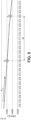
- recovery tank if the geometry of this tank is known. This is the case for the examples of curves represented in the figures 2 to 6 , where the x-axis represents time and the y-axis represents a volume of water in the recovery tank.
- the monitoring system 4 includes a water level sensor 42 in the recovery tank, the computer 40 is in communication with it to receive the water quantity measurements made.
- the water temperature sensor 43 of the recovery tank is adapted to measure the temperature of the water contained in the recovery tank or in the circuit, between the recovery tank and upstream of the heat exchanger 135, this last case being represented on the figure 1 .
- the temperature sensor 43 is adapted to carry out measurements continuously or at a determined frequency.
- the monitoring system 4 includes a temperature sensor
- the computer 40 is in communication with it to receive the temperature measurements taken.
- the system 4 for monitoring the operation of the infrastructure further comprises one or more water level sensors in the overflow basin 10.
- this water level sensor water can be a pressure sensor placed at the bottom of the overflow basin, or an ultrasonic sensor or a laser sensor.
- the data obtained by this sensor can be translated into a volume of water, knowing the volume of the overflow basin.
- the computer 40 is configured to analyze the data relating to the temporal evolution of the quantity of water in the recovery tank and/or the temperature of the water in the recovery tank, to detect operating events of the overflow basin, including for example malfunctions, leaks, or equipment breakdowns.
- the computer 40 is also configured to control the controllable systems 13, 31, 32, 33 described above in order to adapt their operation to the events detected.
- controllable systems 13, 31, 32, 33 described above in order to adapt their operation to the events detected.
- This method comprises a step 100 of acquiring, respectively by the water level sensor 42 or by the temperature sensor 43, data relating to the temporal evolution of a quantity of water in the recovery tank or 'a temperature of the water in the recovery tank.
- step 100 also includes the acquisition, by the water level sensor 44 in the overflow basin, of data relating to the temporal evolution of a quantity of water in the overflow basin. overflow.
- this acquisition is carried out at a permanently determined frequency, to be able to permanently monitor the aquatic infrastructure and detect possible events.
- the frequency of acquisition of water quantity or temperature data is preferably at least once per minute, preferably more than once per minute, for example between 1 and 10 times per minute.
- the method comprises the reception 200, by the computer 40, of the data acquired by the sensor(s) 42, 43, and where appropriate 44.
- the data is transmitted by the sensors to the computer 40 progressively. measure of their acquisition. This allows faster detection of possible malfunctions and therefore faster resolution.
- the data can be transmitted to the computer 40 at a frequency lower than their acquisition frequency, for example of the order of one to several times per hour.
- the term "activity level” herein refers to disturbances in the quantity of water overflowing from the basin that are caused by the presence of basin occupants.
- the level of activity depends on the one hand on the affluence, since the higher the number of people present in the basin, the greater the quantity of water displaced by the presence of these people, but it also depends on the type of activity practiced by the occupants, certain activities, particularly sporting or leisure activities (for example: water polo, children's games) being able to cause more significant disruption than others (for example: calm swimming).
- the activity level is a more relevant quantity to know than simply counting the occupants of the pool, since it directly impacts the emission of trichloramine into the air, the humidity level in the air, etc.
- the analysis of the data by the calculator can also make it possible to quantify, if necessary, the water consumption for filling the basin, or water leaks.
- the analysis 300 to supervise the operation of the basin 10 can then make it possible, based on the events detected or the quantities measured, to intervene 400 directly at the level of the controllable systems 13, 31, 32, 33, that is to say say to control one of these systems, for example to adjust a flow of air circulating in the building or the heating of the building, a flow of water filtration, etc. It also allows you to intervene on components of the infrastructure identified as faulty (repair or replacement of valves, crack sealing, etc.)
- the analysis 300 may include determining 310 a set of parameters when the overflow basin is unoccupied, then detecting basin operating events 320, certain events being detected from the parameters determined.
- the determination 310 and detection 320 steps can be repeated at a given frequency, so as to maintain up-to-date parameters for monitoring the operation of the basin, and/or to monitor a temporal evolution of the parameters which are determined at the same time.
- step 310 the method may include a determination 310 of the parameters at each period of unoccupancy, for example at night, and the detection of operating events of the pool 320 during periods of occupation.
- the unoccupied state of the pool can be inferred from the times the aquatic infrastructure is closed to the public.
- it can be determined when a dispersion indicator, for example a standard deviation, of a series of consecutive measurements of the quantity of water in the recovery tank, is less than a determined threshold.
- this quantity of water is, outside the periods of activity of the basin, and outside of any leak or malfunction of equipment, substantially constant or slightly decreasing over time, this decrease possibly being linked to a progressive evaporation of the water contained in the overflow basin 10.
- This decrease also reflects a decrease in the volume of water in the overflow basin 10. To compensate this drop, automatic fillings, take place when the volume of water in the overflow basin reaches a minimum volume.
- the quantity of water V min corresponding to the minimum volume triggering automatic filling can be configured as the quantity of water in the recovery tank when filling takes place during a period of inactivity of the basin. This filling can be programmed, therefore known a priori, or automatically detected as a sudden increase in the quantity of water in the recovery tank.
- the quantity of water V max in the recovery tank 12 corresponding to the high level of the overflow basin after filling can also be determined as the quantity of water reached in the tank 12 after filling in a period unoccupancy of the basin.
- Step 310 can also include determining the duration of the filling D R and a volume of the filling VR.
- the filling duration can be determined solely from the temporal evolution of the quantity of water in the basin, as being the period of time elapsed between the start of the increase in the quantity of water in the tank. recovery from the quantity V min and reaching the “high” level corresponding to the quantity V max .
- the filling volume can be determined from the temporal evolution of the quantity of water in the recovery tank 12, by measuring the difference between the quantity of water measured at the end of filling and at the end of filling. start of filling. This difference can be determined directly in volume, or otherwise in water level, and can be translated into volume by knowing the geometry of the recovery tank.
- a filling rate can then be deduced from the filling duration and the filling volume. Determining the filling flow rate is advantageous to then make it possible to determine the volume of water consumed during subsequent fillings. As indicated previously, step 310 can be repeated subsequently to update certain parameters, and in particular the filling flow rate, the value of which can vary depending on the pressure of the water distribution network.
- the determination 310 of the parameters during a period of inactivity or unoccupancy of the basin may include the determination of the temporal slope Pn of the quantity of water in the recovery tank corresponding to a nominal loss rate of the basin at overflow.
- this nominal loss rate corresponds to the evaporation of water from the overflow basin.
- This slope can be calculated by the difference in the quantity of water measured over a determined period of time, outside a period of filling of the overflow basin 10, and during a period of inactivity of this basin.
- This slope which we describe as nominal, is assumed to be substantially constant and negative, so that monitoring the temporal evolution of this slope can make it possible to detect malfunctions in the infrastructure.
- a slope less than the nominal slope that is to say a reduction in the quantity of water greater, in absolute value, than that observed for the nominal slope, subject to a determined tolerance, is indicative of a leak in the infrastructure, for example at a pipe, valve, crack, etc.
- a slope greater than the nominal slope that is to say a reduction in the quantity of water smaller than that observed for the nominal slope, or even a progressive increase in the quantity of water in the tank recovery 12 is indicative of a failure in the filling of the overflow basin, for example at the level of a supply valve which no longer closes or a progressive clogging of the filters.
- the computer 40 can be configured to detect 320 basin operating events.
- the calculator 40 can be configured to detect fillings of the basin, including during periods of activity.
- a filling is detected when a set of conditions is respected, including at least the fact that a sudden increase in the quantity of water in the recovery tank takes place, from a quantity of water less than or equal to the quantity V min corresponding to the minimum volume in the overflow basin - this comparison can be carried out subject to a determined tolerance.
- the set of conditions also includes a condition on the slope of the increase in the quantity of water in the recovery tank 12, which must be greater than or equal to a determined threshold.
- the set of conditions can also include a condition on a maximum value that the quantity of water in the recovery tank 12 must not exceed, subject to a determined tolerance, this maximum value corresponding to the high level V max configured after filling the tank recovery.
- the set of conditions for detecting filling can also include a condition on the water temperature of the tank. recovery, which must decrease during the filling period, ie during the period when the quantity of water in the recovery tank increases. Indeed, the new water being injected into the circuit at the level of the recovery tank, a filling can be detected by the high impact of the volume of new water injected on the temperature of the water in the recovery tank or in downstream of it. This condition on a drop in temperature allows more reliable detection of filling, because a sudden increase in the quantity of water in the basin can also be linked to a massive and rapid influx of occupants into the basin.
- Detecting filling may also include determining a filling duration D R and a filling volume VR.
- the filling duration can be determined solely from the temporal evolution of the quantity of water in the basin, as being the period of time elapsed between the start of the increase in the quantity of water in the tank. recovery and reaching the “high” level which mechanically stops this filling.
- the filling duration can alternatively, or in addition, be determined from the temporal evolution of the water temperature in the recovery tank, as being the period elapsed between the start and the end of the reduction in temperature of the water. In this figure, we identify two fillings of respective durations D R1 , D R2 .
- the filling volume can then be determined from the filling duration and the filling flow rate which was determined in step 310 during a period of unoccupancy of the basin.
- the cumulative volume of fillings is advantageously calculated to monitor the structure's water consumption and detect possible leaks.
- analysis 300 of the received data may also include detection 320 of filter washing.
- detection 320 of filter washing In reference to the Figure 4 , we have shown an example of temporal evolution of the quantity of water in the recovery tank (left axis) and temperature (right axis) during filter washing.
- a filter wash consists of several phases whose effects are detectable on the temperature and water quantity curves in the recovery tank.
- Filter washing includes a step of stopping the pump(s) 130 - point 1 on the Figure 4 - which results in an increase in the quantity of water in the tank, this increase being able to reach a quantity of water in the recovery tank greater than that reached after filling.
- stopping the filtration causes a new state of equilibrium in the overflow basin where it no longer overflows after a given time because all the water located above the level of the chutes 11 has flowed into the tank. recovery 12. Stopping of the pump 130 can also be detected on the temperature curve in the case where the temperature sensor is positioned in the vicinity of the heat exchanger, because the immobilized water can heat up significantly depending on the positioning of the sensor and the circulation of hot water in the primary of the exchanger.
- the filter is washed when the pump is turned off, then the pump is turned back on, causing both a drop in the amount of water in the collection tank, in order to transfer the water back to the basin overflow, and a drop in temperature (points 2: end of rinsing and 3: restart of the pump on the Figure 4 ).
- the washing is followed by one or more automatic fillings which can be detected by the conditions presented above, because the evacuated water must be replaced and passes through the recovery tank.
- This succession of steps is detectable by monitoring at least the temporal evolution of the water level in the recovery tank, preferably combined with monitoring the temporal evolution of the water temperature in the recovery tank. recovery or downstream thereof.
- the water level and temperature profile during filter washing can nevertheless vary greatly from one infrastructure to another, depending on the volume of the recovery tank, the volume of water necessary to wash the filter, etc.
- the detection of filter washing can therefore be carried out by application of a previously trained automatic learning model, for example by supervised learning on temporal sequences of water temperature and water level. water in the recovery tank corresponding to filter washing or corresponding to other types of events.
- the three conditions stated above are cumulative to detect filter washing.
- a nominal quantity of water V n in the recovery tank can be deduced during step 320 at a given instant, from a known initial quantity V i and the elapsed time ⁇ t between the instant considered and this initial quantity.
- V n (t) V i - P n * ⁇ t.
- the known initial quantity may be the quantity of water reached in the recovery tank after filling.
- the method can include a posteriori correction of the wrongly detected filling, with the reduction or elimination of the corresponding volume of water consumed.
- the nominal quantity of water V n mentioned above is therefore a theoretical quantity of water, in the absence of any activity in the basin and any malfunction impacting the nominal slope.
- This nominal quantity of water being known, we can then evaluate a level of activity in the overflow basin by the difference between the quantity of water measured V R (t) in the recovery tank and this nominal quantity.
- V R (t) the quantity of water measured in the recovery tank
- the nominal quantity of water was represented as a function of time in dotted lines, and the difference measured between the actual quantity and this line corresponds to the activity of the basin.
- the difference between the total activity and the dynamic component (obtained through conversions taking into account the respective volumes of each basin) provides access to the static activity which can be reduced to a variation in water volume and therefore to a overall mass of all the occupants of the pool.
Landscapes
- Engineering & Computer Science (AREA)
- Architecture (AREA)
- Physics & Mathematics (AREA)
- Civil Engineering (AREA)
- General Physics & Mathematics (AREA)
- Automation & Control Theory (AREA)
- Water Supply & Treatment (AREA)
- Structural Engineering (AREA)
- Mathematical Physics (AREA)
- Evolutionary Computation (AREA)
- Artificial Intelligence (AREA)
- Management, Administration, Business Operations System, And Electronic Commerce (AREA)
- Examining Or Testing Airtightness (AREA)
Applications Claiming Priority (1)
| Application Number | Priority Date | Filing Date | Title |
|---|---|---|---|
| FR2300313A FR3145006A1 (fr) | 2023-01-12 | 2023-01-12 | Procede et systeme de surveillance de l’exploitation d’une infrastructure aquatique |
Publications (1)
| Publication Number | Publication Date |
|---|---|
| EP4400675A1 true EP4400675A1 (de) | 2024-07-17 |
Family
ID=89573829
Family Applications (1)
| Application Number | Title | Priority Date | Filing Date |
|---|---|---|---|
| EP24151557.6A Pending EP4400675A1 (de) | 2023-01-12 | 2024-01-12 | Verfahren und system zur überwachung des betriebs einer wasserinfrastruktur |
Country Status (2)
| Country | Link |
|---|---|
| EP (1) | EP4400675A1 (de) |
| FR (1) | FR3145006A1 (de) |
Citations (6)
| Publication number | Priority date | Publication date | Assignee | Title |
|---|---|---|---|---|
| US4686718A (en) | 1985-03-25 | 1987-08-18 | Aqua Systems, Inc. | Method and apparatus for automatically maintaining a predetermined desired level of water in a swimming pool, and the like |
| JPH06264630A (ja) * | 1992-10-06 | 1994-09-20 | Richard E D Mcclish | 水泳プール |
| US20020078735A1 (en) | 2000-12-05 | 2002-06-27 | John Bromley | Apparatus and method for detecting a leak in a swimming pool |
| FR3100552A1 (fr) | 2019-09-11 | 2021-03-12 | Paul-Henri Mathis | Elément de construction et procédé de production d’au moins un élément de construction à partir d’un rondin de bois |
| US20210341956A1 (en) * | 2020-05-01 | 2021-11-04 | Poolside Tech, LLC | Systems and methods for regulating temperatures of pool systems |
| US20220107614A1 (en) * | 2020-10-02 | 2022-04-07 | Sentry Valve Company, Inc. | Systems, methods, and apparatus to monitor and control an aquatic facility |
-
2023
- 2023-01-12 FR FR2300313A patent/FR3145006A1/fr not_active Withdrawn
-
2024
- 2024-01-12 EP EP24151557.6A patent/EP4400675A1/de active Pending
Patent Citations (6)
| Publication number | Priority date | Publication date | Assignee | Title |
|---|---|---|---|---|
| US4686718A (en) | 1985-03-25 | 1987-08-18 | Aqua Systems, Inc. | Method and apparatus for automatically maintaining a predetermined desired level of water in a swimming pool, and the like |
| JPH06264630A (ja) * | 1992-10-06 | 1994-09-20 | Richard E D Mcclish | 水泳プール |
| US20020078735A1 (en) | 2000-12-05 | 2002-06-27 | John Bromley | Apparatus and method for detecting a leak in a swimming pool |
| FR3100552A1 (fr) | 2019-09-11 | 2021-03-12 | Paul-Henri Mathis | Elément de construction et procédé de production d’au moins un élément de construction à partir d’un rondin de bois |
| US20210341956A1 (en) * | 2020-05-01 | 2021-11-04 | Poolside Tech, LLC | Systems and methods for regulating temperatures of pool systems |
| US20220107614A1 (en) * | 2020-10-02 | 2022-04-07 | Sentry Valve Company, Inc. | Systems, methods, and apparatus to monitor and control an aquatic facility |
Also Published As
| Publication number | Publication date |
|---|---|
| FR3145006A1 (fr) | 2024-07-19 |
Similar Documents
| Publication | Publication Date | Title |
|---|---|---|
| WO2011004015A2 (fr) | Gestion d'un parc de piscines | |
| WO2010049913A2 (en) | Intelligent flushing system | |
| CN118707889B (zh) | 一种基于物联网的砂滤器智能控制系统 | |
| US20160312447A1 (en) | Regulation method for water hybrid devices involving purification, circulation and/or separation | |
| CA2954812A1 (fr) | Procede pour detecter des anomalies dans un reseau de distribution, en particulier d'eau potable | |
| KR102259536B1 (ko) | 지능형 상수도 관로 자동 플러싱 시스템 및 방법 | |
| EP4400675A1 (de) | Verfahren und system zur überwachung des betriebs einer wasserinfrastruktur | |
| JP2022134292A (ja) | ろ過装置の洗浄監視方法および洗浄監視システム | |
| EP2913786B1 (de) | Abschätzung des Stromverbrauchs eines bestimmten Geräts unter mehreren elektrischen Geräten | |
| EP3816854A1 (de) | Verfahren und vorrichtung zur verbesserten kontrolle von schwimmbädern | |
| CN121085346B (zh) | 一种基于人工智能洪水渗滤净化系统 | |
| EP3181025B1 (de) | Heizvorrichtung, bevorzugt ein handtuchtrockner, zur heizung eines badezimmers | |
| CN106705517A (zh) | 蒸发式冷凝设备的排污换水控制方法 | |
| EP3449102B1 (de) | Verwaltung von wasserversorgungspumpen für eine stromerzeugungsanlagenkreis | |
| CN113761752B (zh) | 一种基于水龄控制的二次供水储水设备总氯保障方法及系统 | |
| US20240169459A1 (en) | Systems and Methods for Detecting Emergency Conditions Within Structures and Initiating Remediation Procedures | |
| FR3140877A1 (fr) | Procédé et dispositif de désinfection de l'eau d'une piscine. | |
| FR3104239A1 (fr) | système pilotant un dispositif de renouvellement d’air d’une zone et un dispositif de chauffage de la zone | |
| CN206320920U (zh) | 一种热水器 | |
| CN120687983B (zh) | 基于物联网的水利水电设备远程运维管理系统 | |
| KR102717222B1 (ko) | Ai 시각인지 기술을 적용한 제진기 제어 방법 및 시스템 | |
| CN119288040A (zh) | 排水控制方法、装置、计算机设备和存储介质 | |
| WO2021089937A1 (fr) | Procede de detection du blocage de dispositifs de comptage sur un reseau de distribution | |
| US20240167469A1 (en) | Systems and Methods for Determining Health Statuses of Devices Within a Structure | |
| EP4591123A1 (de) | Verfahren zur überwachung des flüssigkeitsverbrauchs eines zu überwachenden gebäudes durch klassifizierung von flüssigkeitsverbrauchsereignissen mittels überwachten lernens |
Legal Events
| Date | Code | Title | Description |
|---|---|---|---|
| PUAI | Public reference made under article 153(3) epc to a published international application that has entered the european phase |
Free format text: ORIGINAL CODE: 0009012 |
|
| STAA | Information on the status of an ep patent application or granted ep patent |
Free format text: STATUS: THE APPLICATION HAS BEEN PUBLISHED |
|
| AK | Designated contracting states |
Kind code of ref document: A1 Designated state(s): AL AT BE BG CH CY CZ DE DK EE ES FI FR GB GR HR HU IE IS IT LI LT LU LV MC ME MK MT NL NO PL PT RO RS SE SI SK SM TR |
|
| 19U | Interruption of proceedings before grant |
Effective date: 20241106 |