EP4401054A1 - Unité de transport pour un dispositif de manipulation de documents de valeur - Google Patents
Unité de transport pour un dispositif de manipulation de documents de valeur Download PDFInfo
- Publication number
- EP4401054A1 EP4401054A1 EP23150989.4A EP23150989A EP4401054A1 EP 4401054 A1 EP4401054 A1 EP 4401054A1 EP 23150989 A EP23150989 A EP 23150989A EP 4401054 A1 EP4401054 A1 EP 4401054A1
- Authority
- EP
- European Patent Office
- Prior art keywords
- transport path
- transport
- guide element
- value
- notes
- Prior art date
- Legal status (The legal status is an assumption and is not a legal conclusion. Google has not performed a legal analysis and makes no representation as to the accuracy of the status listed.)
- Granted
Links
Images




Classifications
-
- G—PHYSICS
- G07—CHECKING-DEVICES
- G07D—HANDLING OF COINS OR VALUABLE PAPERS, e.g. TESTING, SORTING BY DENOMINATIONS, COUNTING, DISPENSING, CHANGING OR DEPOSITING
- G07D11/00—Devices accepting coins; Devices accepting, dispensing, sorting or counting valuable papers
- G07D11/10—Mechanical details
- G07D11/16—Handling of valuable papers
-
- G—PHYSICS
- G07—CHECKING-DEVICES
- G07D—HANDLING OF COINS OR VALUABLE PAPERS, e.g. TESTING, SORTING BY DENOMINATIONS, COUNTING, DISPENSING, CHANGING OR DEPOSITING
- G07D7/00—Testing specially adapted to determine the identity or genuineness of valuable papers or for segregating those which are unacceptable, e.g. banknotes that are alien to a currency
- G07D7/06—Testing specially adapted to determine the identity or genuineness of valuable papers or for segregating those which are unacceptable, e.g. banknotes that are alien to a currency using wave or particle radiation
- G07D7/12—Visible light, infrared or ultraviolet radiation
- G07D7/121—Apparatus characterised by sensor details
-
- G—PHYSICS
- G07—CHECKING-DEVICES
- G07D—HANDLING OF COINS OR VALUABLE PAPERS, e.g. TESTING, SORTING BY DENOMINATIONS, COUNTING, DISPENSING, CHANGING OR DEPOSITING
- G07D7/00—Testing specially adapted to determine the identity or genuineness of valuable papers or for segregating those which are unacceptable, e.g. banknotes that are alien to a currency
- G07D7/17—Apparatus characterised by positioning means or by means responsive to positioning
Definitions
- the invention relates to a transport unit for a device for handling notes of value, as well as a method for removing a jam of notes of value in the transport unit.
- valuables jams can occur when valuables are transported within the device. For example, valuables jams occur when one or more valuables become jammed or are pulled diagonally in the device's transport unit. A valuables jam can then lead to a transport path in the device's transport unit being blocked.
- banknote jams can be largely avoided by generously dimensioning the transport paths of the device.
- the transport paths can be designed so that they are high enough to be able to transport crumpled banknotes without causing a banknote jam. This also makes it possible to transport several banknotes that could not be separated safely along the transport paths without causing banknote jams.
- a transport unit for a device for handling notes of value comprises a first transport path limiting element and a second transport path limiting element, which are arranged and spaced apart from one another in such a way that a transport path is formed between the transport path limiting elements and notes of value can be transported along the transport path. Furthermore, the transport unit comprises at least one sensor, which is designed is to recognize at least one security feature of the notes of value transported along the transport path.
- the transport unit comprises at least one guide element which is arranged movably and is movable at least between two positions, wherein the guide element in a first position is arranged at least partially in the transport path and is further designed to limit the height of the transport path in a detection area of the sensor to a first distance, wherein the guide element in a second position is not arranged in the transport path.
- the transport path limitation elements are located in particular opposite the front or back of the security note.
- the guide element allows a note of value to be guided particularly close to the sensor during transport along the transport route.
- the detection area of the sensor is directed at the transport path at least through an opening of the first transport path limiting element. In this way, security features of the note of value can be determined particularly precisely and reliably.
- the senor is a magnetic sensor. This allows magnetic security features of the note of value, in particular magnetic inks, to be detected.
- the senor is arranged flush with a side of the first transport path limiting element facing the transport path. This ensures safe transport of the notes of value along the transport path.
- the guide element in the first position extends into the transport path through at least one opening of the second transport path limiting element. This allows the guide element to be arranged in the transport path opposite the sensor and to guide notes of value close to the sensor.
- the second transport path limiting element is set back from the transport path in the area of the opening, in particular is concave, and the guide element in its second position is arranged at least partially flush with a side of the second transport path limiting element facing the transport path in the area.
- the guide element can therefore variably either form a bottleneck or open up the transport path.
- a contact area of the guide element for contact with the note of value is arranged to be movable transverse to a transport direction of the notes of value along the transport path between the first and the second position, in particular the guide element extends substantially across a width of the transport path transverse to Transport direction. Furthermore, the contact area has a convex shape, particularly on the side facing the transport path. This allows the note of value to be guided past the sensor particularly safely during transport along the transport path, especially when the guide element is in its first position.
- the guide element is held in the first position by means of a spring force exerted by a spring element or is spring-mounted. This allows the guide element to be moved, in particular by bent notes of value or in the case of multiple withdrawals, thus preventing a jam of notes of value in the area of the guide element.
- the guide element can be moved at least into the second position with the help of a lifting magnet. This allows the guide element to be moved particularly flexibly.
- the guide element can be moved at least between the first position and the second position using a motor. This allows the guide element to be moved particularly flexibly.
- the senor and the guide element are arranged along a plane transversely or perpendicularly to the transport path.
- the detection range of the sensor also extends over at least part of the width of the transport path. This ensures that the note of value is guided past the sensor particularly safely during transport along the transport path.
- the first distance has a value in a range of 0.5 mm to 1.5 mm, in particular 1 mm. In particular, this also corresponds to a distance between the sensor and the guide element or the contact area of the guide element. This enables the security features of the note of value to be recognized particularly precisely by the sensor.
- the first transport path limiting element is spaced from the second transport path limiting element by a distance in a range of 2 mm to 4 mm, preferably in a range of 2.5 mm to 3.5 mm, in particular 3 mm. This prevents banknote jams.
- the first transport path limiting element is spaced from the second transport path limiting element in a first transport path region arranged in the transport direction in front of the detection region of the sensor by a distance in a range of 2 mm to 4 mm, preferably in a range of 2.5 mm to 3.5 mm, in particular of 3 mm, and wherein the first transport path limiting element is spaced from the second
- the transport path limiting element has a distance in a range of 1 mm to 2 mm, in particular 1.5 mm, in a second transport path area arranged in the transport direction after the detection area. This enables additional sensors in the transport direction after the guide element to particularly reliably determine features of the note of value.
- the transport unit preferably comprises a second sensor which is designed to detect at least one security feature of notes of value transported through the second transport path area.
- the second sensor can in particular be an optical sensor. This enables a particularly secure check of the note of value.
- the transport unit includes drive elements for transporting the notes of value along the transport path.
- transport elements such as driven rollers or wheels, can protrude into the transport path through the transport path limiting elements, in particular on both sides. This enables particularly safe transport of the notes of value along the transport path.
- a further aspect relates to a method for removing a banknote jam in a transport unit, comprising the following steps: Determining a banknote jam with at least one banknote along a transport path of the transport unit; Moving a guide element of the transport unit from a first position within the transport path to a second position outside the transport path; and transporting the note of value against a transport direction.
- step a) of the method if a parameter of a drive motor for transporting the banknote along the transport path deviates from an average value or if after a predetermined time the banknote is not detected by a sensor arranged downstream of the transport unit in the transport direction. This allows a banknote jam to be determined reliably and quickly.
- a further aspect relates to a device for handling notes of value comprising at least one transport unit with a guide element with the aforementioned features.
- the device for handling notes of value comprises a control unit which is designed and configured to control at least the guide element according to the method.
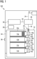
- Figure 1 shows a schematic side view of a device 100 for handling notes of value.
- the device 100 serves both for the deposit of notes of value by an operator and for the withdrawal of notes of value to an operator and is also referred to as a recycling cash machine.
- the device 100 can also serve exclusively for the withdrawal of notes of value or the deposit of notes of value.
- the device 100 can be an automatic cash register system, a self-checkout cash register or a so-called automatic safe cash register.
- the device 100 comprises a safe 10 in which four cash boxes 12a to 12d are arranged and which protects the cash boxes 12a to 12d from unauthorized access, in particular from theft and attempts at manipulation.
- the safe 10 has a safe door 34 which can be opened and closed via a locking unit 36.
- the cash boxes 12a to 12d are each arranged in a receiving compartment 32a to 32d in the safe 10.
- the cash boxes 12a to 12d are in the embodiment according to Figure 1 arranged horizontally in the device 100. In other devices for handling notes of value, the cash cassettes 12a to 12d can alternatively be arranged vertically.
- the cash boxes 12a to 12d can be removed from the device 100 and are used for storing and transporting notes of value, in particular banknotes and/or checks.
- the notes of value are stored in the cash boxes 12a to 12d in the form of a stack. One of these stacks is indicated in the first cash box 12a, for example.
- One of the notes of value in this stack of notes of value is designated, for example, with the reference number 13.
- the notes of value 13 in the cash cassettes 12a to 12d are arranged standing on one of their edges, preferably on one of their longitudinal edges.
- Each cash box 12a to 12d has an opening for feeding in notes of value 13 and for removing notes of value 13.
- a separating and stacking unit 14a to 14d is arranged, with the help of which, on the one hand, notes of value 13 can be fed into the cash boxes 12a to 12d and on the other hand, notes of value 13 stored in the cash boxes 12a to 12d can be separated from stacks of notes of value held in the cash boxes 12a to 12d and removed from the cash box 12a to 12d.
- each separating and stacking unit 14a to 14d there is a switch 16a to 16d, with the help of which a note of value 13 to be fed to the cash boxes 12a to 12d is branched off from a transport path 18 and fed to the separating and stacking unit 14a to 14d that is arranged in front of the cash box 12a to 12d into which the note of value 13 is to be transported.
- the switches 16a to 16d also serve to transport the notes of value 13 taken from the cash boxes 12a to 12d to the transport path 18.
- the safe 10 also has an opening 20 through which notes of value 13 transported along the transport path 18 can be transported into or out of the safe 10.
- the device 100 further comprises an input and output compartment 22 through which notes of value 13 to be deposited can be issued to an operator by an operator.
- notes of value 13 to be deposited can be issued to an operator by an operator.
- only notes of value 13 are dispensed via the input and output compartment 22, and in the case of a pure depositing ATM, only notes of value 13 are deposited via the input and output compartment 22.
- the notes of value 13 deposited via the input and output compartment 22 are separated and fed individually along the transport path 24 to a reading unit 26, with the help of which, for example, the authenticity, the nominal value and/or the Serial number of each deposited voucher 13 can be determined.
- vouchers 13 that have been deposited and/or are to be paid out can be temporarily stored in a buffer 30.
- the buffer 30 can temporarily store vouchers 13 that are not suitable for payment and/or vouchers 13 that have been deposited and identified as not genuine by the reading unit 26 or vouchers 13 that have not been removed by an operator.
- Jams of notes of value can occur particularly when notes of value that are already in circulation and are crumpled, dirty or stuck together are transported along the transport paths 18, 24.
- Figure 2 shows a side view of a transport unit 200, in particular for the device 100 for handling notes of value.
- the transport unit 200 can be arranged, for example, along one of the transport paths 18, 24.
- the transport unit 200 can be part of the reading unit 26, which serves to recognize security features of the notes of value 13.
- the transport unit 200 comprises a first transport path limiting element 202 and a second transport path limiting element 204, between which a transport path 206 is formed.
- notes of value 13 can be transported in particular in a transport direction along the arrow P1.
- the transport unit 200 comprises a guide element 208, which is arranged in a Figure 2 shown first position through an opening of the second transport path delimiting element 204 into the transport path 206.
- the transport unit 200 comprises at least one sensor 210 which can detect security features of the notes of value 13 transported along the transport path 206.
- the senor 210 is arranged in an opening of the first transport path delimiting element 202 so that the sensor 210 is arranged flush with a side of the first transport path delimiting element 202 facing the transport path 206.
- the sensor 210 is thus arranged opposite the guide element 208 with respect to the transport path 206.
- a detection area of the sensor 210 is located in the transport path 206.
- the first transport path limiting element 202 has a distance 211 from the second transport path limiting element 204 in a range of 2 mm to 4 mm, preferably in a range of 2.5 mm to 3.5 mm, in particular 3 mm.
- a contact area 212 of the guide element 208 is spaced apart from a side of the sensor 210 facing the transport path 206, in particular in the detection area of the sensor 210, or the side of the first transport path limiting element 202 facing the transport path 206, in a range of 0.5 mm to 1.5 mm, in particular 1 mm.
- the distance is identified by reference numeral 214.
- the distance 214 between the sensor 210 and the guide element 208 in its first position is in particular smaller than the distance between the transport path limiting elements 202, 204.
- notes of value 13 are guided along the transport path 206 in the direction of arrow P1 through the transport unit 200.
- the transport path limiting elements 202, 204, the sensor 210 or the guide element 208 since the notes of value 13 are each separated from the elements 202, 204, 208, 210 by an air gap.
- notes of value 13 to be transported are, for example, heavily bent or if several notes of value 13 are transported at once along the transport path 206 due to multiple withdrawals, can there be fundamentally undesirable contact with the elements 202, 204, 208, 210. Due to the reduced distance 214 compared to the distance 211, it is therefore possible that notes of value 13 get stuck at this bottleneck and a jam of notes of value occurs.
- the reduced distance 214 is necessary in order to reliably detect or read security features of the notes of value 13 with the aid of the sensor 210.
- the sensor 210 can in particular be a magnetic sensor that detects magnetic features of the notes of value 13 while the notes of value 13 are transported past the sensor 210.
- notes of value 13 can be printed with magnetic printing ink, so that the printed images made of magnetic printing ink are detected with the aid of the sensor 210.
- the transport unit 200 can comprise driven wheels 216, 218, 220, 222, with the aid of which notes of value 13 can be transported along the transport path 206 and past the sensor 210.
- the guide element 208 can preferably be spring-mounted.
- the transport unit 200 comprises a spring 224, which holds the guide element 208 in the first position with the aid of a spring force.
- Figure 3 shows a perspective view of the second transport path limiting element 204 with the guide element 208 in a second position.
- the guide element 208 is pivoted out of the transport path 206.
- the guide element 208 is arranged flush with the side of the second transport path limiting element 204 facing the transport path 206.
- the contact surface 212 of the guide element 208 is arranged flush.
- the guide element 208 can comprise several finger-shaped regions, each with one of the contact regions 212, which are each arranged between rib-shaped regions 300 of the second transport path limiting element 204.
- the rib-shaped regions 300 of the second transport path limiting element 204 are thus openings through which the finger-shaped regions of the guide element 208 can be introduced into the transport path 208. Furthermore, the rib-shaped regions 300 of the second transport path limiting element 204 can be set back on the side of the second transport path limiting element 204 facing the transport path 206 and can in particular be concave.
- the guide element 208 in particular the contact areas 212, preferably have a rounded or convex shape, so that when the guide element 208 is arranged in the first position, in particular no edges on which notes of value 13 can get caught protrude into the transport path 206 in and against the transport direction P1.
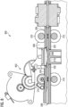
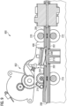
- Figures 4 and 5 show a side view of a transport unit 400 with a lifting magnet 402, which is connected to the guide element 208 via a lever 404 and the guide element 208 from the Figure 4 shown first position about a rotation axis 406 into the Figure 5 shown second position.
- the preferably spring-mounted guide element 208 can in particular also be moved into the second position when the lifting magnet 402 does not move the guide element 208 and a force opposite to and greater than the spring force acts on the guide element 208.
- Figures 6 and 7 show detailed views of the guide element 208 of the transport unit 400 after Figures 4 or 5.
- Figure 6 shows the guide element 208 in the first position.
- the transport path 206 is limited to the distance 214 at the point at which the guide element 208 protrudes into the transport path 206 in order to guide notes of value 13 close to the sensor 210, as already described above.
- the distance 700 between the sensor 210 and the contact area 212 of the guide element 208 is increased compared to the first position.
- the distance 700 is in a range of 2 mm to 4 mm, preferably in a range of 2.5 mm to 3.5 mm, in particular 3 mm.
- the transport path 206 is extended in the area between the guide element 208 and the sensor 210 and has a height equal to the distance 700.
- the height of the Transport path 206 in the area between the guide element 208 and the sensor 210 is increased to the distance 700 when the guide element 208 is in the second position.
- the transport path 206 in the area between the guide element 208 and the sensor 210 is also increased.
- the bottleneck that occurs when the guide element 208 is in its first position can thus be avoided or eliminated by pivoting the guide element 208 into its second position.
- Figure 8 and Figure 9 show a transport unit 800.
- the guide element 208 of the transport unit 800 is made of the Figure 8 shown first position in the Figure 9
- the second position shown can be moved by means of a motor via a gear or pivoted about the rotation axis 406.
- Figures 10 to 13 show sectional views of a transport unit with a guide element 1002.
- the transport unit 1000 has the same functions as already described for the transport units 200, 400, 800 above.
- the guide element 1002 is in a first position in which the guide element 1002 protrudes into a transport path 1004 for notes of value 13 between a first transport path limiting element 1006 and a second transport path limiting element 1008.
- the transport unit 1000 also comprises a sensor 1010 which can detect security features of the notes of value 13 transported along the transport path 1004.
- the guide element 1002 can be moved between the positions of the guide element 1002 by means of a lifting magnet 1011.
- the transport path limiting elements 1006, 1008 of the transport unit 1000 are variably spaced apart from one another.
- the transport path limiting elements 1006, 1008 are spaced apart 1200 from one another.
- the transport path limiting elements 1006, 1008 are spaced apart 1202 from one another.
- the distance 1200 is in a range from 2 mm to 4 mm, preferably in a range from 2.5 mm to 3.5 mm, in particular 3 mm.
- the distance 1202 is in a range from 1 mm to 2 mm, in particular 1.5 mm.
- the guide element 1002 is thus located at a transition between the distances 1200 and 1202 of the transport path limiting elements 1006, 1008.
- a distance 1204 of a contact area 1206 of the guide element 1202 in its first position from the sensor 1010, in particular a side of the sensor 1010 facing the transport path 1004 or in a detection area of the sensor 1010, is in a range of 0.5 mm to 1.5 mm, in particular 1 mm.
- the guide element 1002 forms a bottleneck along the transport path 1004 in order to guide notes of value close to the sensor 1010.
- the height 1302 of the transport path 1004 in the detection range of the sensor 1010 corresponds to the distance 1200 of the transport path limiting elements 1006, 1008 in the first transport path area.
- the bottleneck generated by the guide element 1002 in its first position is thus increased or eliminated in its second position.
- the guide element 1002 may have finger-shaped elements arranged between rib-shaped regions 1300 of the second transport path limiting element 1008.
- the transport units 200, 400, 800, 1000 can also comprise further sensors, in particular light barriers and cameras.
- Figures 10 to 13 in which a camera, in particular a spectral camera, with a first camera module 1012 and a second camera module 1014 of the transport unit 1000 is shown.
- the first camera module 1012 is arranged in an opening of the first transport path limiting element 1006 and is directed towards the transport path 1004.
- the second camera module 1014 is arranged in an opening of the second transport path limiting element 1008 and is directed towards the transport path 1004.
- the front and back of notes of value 13 that are transported along the transport path 1004 can thus be recorded simultaneously with the aid of the camera modules 1012, 1014.
- Figure 14 shows a time course diagram with parameters of actuators and sensors of one of the transport units 200, 400, 800, 1000.
- Actuators can be, for example, drive motors for the driven wheels 216, 218, 220, 222.
- the sensors can be, for example, light barriers, the camera 1012, 1014 or the sensors 210, 1010.
- banknote jams can be determined and based on this, the position of the guide elements 208, 1002 can be changed, in particular from the first to the second position. In this way, the bottleneck can be removed.
- the banknote jam can then be cleared by transporting the banknote(s) 13 causing the banknote jam in the opposite direction to the transport direction P1, P2.
- parameters of light barriers or the camera 1012, 1014 can be used to determine banknote jams. To do this, it can be determined whether a light barrier arranged in the transport direction P1, P2 after the bottleneck or the guide elements 208, 1002 is triggered by banknotes 13 that were transported along the transport direction P1, P2 by the transport unit 200, 400, 800, 1000 or not. If the light barrier is not triggered after a predetermined time despite the banknote 13 being expected, a banknote jam can be determined.
- Figure 14 are shown the course of light barrier signals that are regularly interrupted by properly transported notes of value 13.
- the light barriers are not interrupted despite a transported note of value 13, so that a jam of notes of value is detected.
- a banknote jam can be detected by an increase 1406 in the motor current of the driven wheels 216, 218, 220, 222. Furthermore, a banknote jam can be detected by a deviation 1408 in the speed of the driven wheels 216, 218, 220, 222 or the motor for the driven wheels 216, 218, 220, 222.
- the guide element 208, 1002 can be moved into the second position and the banknote jam can thus be cleared, in particular by transporting the banknotes 13 causing the banknote jam against the transport direction P1, P2.
Landscapes
- Physics & Mathematics (AREA)
- General Physics & Mathematics (AREA)
- Health & Medical Sciences (AREA)
- General Health & Medical Sciences (AREA)
- Toxicology (AREA)
- Controlling Sheets Or Webs (AREA)
Priority Applications (2)
| Application Number | Priority Date | Filing Date | Title |
|---|---|---|---|
| EP23150989.4A EP4401054B1 (fr) | 2023-01-10 | 2023-01-10 | Unité de transport pour un dispositif de manipulation de documents de valeur |
| PCT/EP2024/050363 WO2024149739A1 (fr) | 2023-01-10 | 2024-01-09 | Unité de transport pour un dispositif de manutention de documents de valeur |
Applications Claiming Priority (1)
| Application Number | Priority Date | Filing Date | Title |
|---|---|---|---|
| EP23150989.4A EP4401054B1 (fr) | 2023-01-10 | 2023-01-10 | Unité de transport pour un dispositif de manipulation de documents de valeur |
Publications (2)
| Publication Number | Publication Date |
|---|---|
| EP4401054A1 true EP4401054A1 (fr) | 2024-07-17 |
| EP4401054B1 EP4401054B1 (fr) | 2025-07-30 |
Family
ID=84901623
Family Applications (1)
| Application Number | Title | Priority Date | Filing Date |
|---|---|---|---|
| EP23150989.4A Active EP4401054B1 (fr) | 2023-01-10 | 2023-01-10 | Unité de transport pour un dispositif de manipulation de documents de valeur |
Country Status (2)
| Country | Link |
|---|---|
| EP (1) | EP4401054B1 (fr) |
| WO (1) | WO2024149739A1 (fr) |
Families Citing this family (1)
| Publication number | Priority date | Publication date | Assignee | Title |
|---|---|---|---|---|
| IT202200024795A1 (it) * | 2022-12-01 | 2024-06-01 | Arca Tech S R L | Dispositivo per la validazione di documenti flessibili |
Citations (2)
| Publication number | Priority date | Publication date | Assignee | Title |
|---|---|---|---|---|
| US20150210495A1 (en) * | 2014-01-29 | 2015-07-30 | Mei, Inc. | Validator With A Dynamic Document Path Height |
| US20160335825A1 (en) * | 2014-04-28 | 2016-11-17 | Oki Electric Industry Co., Ltd. | Determination apparatus and medium transaction apparatus |
-
2023
- 2023-01-10 EP EP23150989.4A patent/EP4401054B1/fr active Active
-
2024
- 2024-01-09 WO PCT/EP2024/050363 patent/WO2024149739A1/fr not_active Ceased
Patent Citations (2)
| Publication number | Priority date | Publication date | Assignee | Title |
|---|---|---|---|---|
| US20150210495A1 (en) * | 2014-01-29 | 2015-07-30 | Mei, Inc. | Validator With A Dynamic Document Path Height |
| US20160335825A1 (en) * | 2014-04-28 | 2016-11-17 | Oki Electric Industry Co., Ltd. | Determination apparatus and medium transaction apparatus |
Also Published As
| Publication number | Publication date |
|---|---|
| EP4401054B1 (fr) | 2025-07-30 |
| WO2024149739A1 (fr) | 2024-07-18 |
Similar Documents
| Publication | Publication Date | Title |
|---|---|---|
| EP2676247B1 (fr) | Dispositif pour manipuler des papiers de valeur comprenant une unité d'orientation pour orienter billets de banque et chèques | |
| DE69306231T2 (de) | Dokumenthandhabung versehen mit einer Klappe | |
| EP2489617B1 (fr) | Dispositif d'alignement de documents de valeur | |
| DE69938327T2 (de) | Banknotenausgeber | |
| EP2675740B1 (fr) | Dispositif de manipulation de documents de valeur comprenant deux systèmes de stockage temporaire pour stocker temporairement les documents de valeurs | |
| EP2675739B1 (fr) | Dispositif de manipulation de documents de valeur comprenant un module d'alimentation à éléments de retenue mobiles | |
| EP2227790A1 (fr) | Dispositif de prise en charge et d'émission de billets de banque | |
| EP4401054B1 (fr) | Unité de transport pour un dispositif de manipulation de documents de valeur | |
| DE102010004580A1 (de) | Vorrichtung zur Handhabung von Wertscheinen mit einer Transportpfadüberwachung | |
| EP2675741B1 (fr) | Dispositif de manipulation de documents de valeur comprenant une unité de regroupement de piles | |
| EP1331185B1 (fr) | Dispositif pour aligner des objets sous forme de feuilles | |
| DE10210689A1 (de) | Vorrichtung für die Annahme und/oder Ausgabe von Banknoten | |
| EP2676249B1 (fr) | Procédé permettant de déliasser une liasse de billets/chèques | |
| DE10350120A1 (de) | Vorrichtungen zur Bearbeitung von Blattgut | |
| EP1387811B1 (fr) | Dispositif et procede pour introduire et deposer des billets de banque | |
| EP2419356B1 (fr) | Dispositif pour entrer un ou plusieurs documents de valeur | |
| WO2012110586A1 (fr) | Dispositif d'oblitération de chèques | |
| WO2021144397A1 (fr) | Dispositif et procédé de transport de billets de valeur | |
| EP2676248B1 (fr) | Dispositif de manipulation de billets et de chèques | |
| DE102008009054A1 (de) | Vorrichtung für die Annahme und Ausgabe von Banknoten | |
| EP2672469B1 (fr) | Dispositif de manipulation de documents de valeur avec un agencement de capteur pour le positionnement exact du module de tête et de coffre-fort | |
| DE102007062118A1 (de) | Vorrichtung für die Annahme und Ausgabe von Banknoten | |
| WO2009083140A1 (fr) | Installation de réception et d'émission de billets de banque |
Legal Events
| Date | Code | Title | Description |
|---|---|---|---|
| PUAI | Public reference made under article 153(3) epc to a published international application that has entered the european phase |
Free format text: ORIGINAL CODE: 0009012 |
|
| STAA | Information on the status of an ep patent application or granted ep patent |
Free format text: STATUS: THE APPLICATION HAS BEEN PUBLISHED |
|
| AK | Designated contracting states |
Kind code of ref document: A1 Designated state(s): AL AT BE BG CH CY CZ DE DK EE ES FI FR GB GR HR HU IE IS IT LI LT LU LV MC ME MK MT NL NO PL PT RO RS SE SI SK SM TR |
|
| STAA | Information on the status of an ep patent application or granted ep patent |
Free format text: STATUS: REQUEST FOR EXAMINATION WAS MADE |
|
| 17P | Request for examination filed |
Effective date: 20241028 |
|
| RBV | Designated contracting states (corrected) |
Designated state(s): AL AT BE BG CH CY CZ DE DK EE ES FI FR GB GR HR HU IE IS IT LI LT LU LV MC ME MK MT NL NO PL PT RO RS SE SI SK SM TR |
|
| GRAP | Despatch of communication of intention to grant a patent |
Free format text: ORIGINAL CODE: EPIDOSNIGR1 |
|
| STAA | Information on the status of an ep patent application or granted ep patent |
Free format text: STATUS: GRANT OF PATENT IS INTENDED |
|
| INTG | Intention to grant announced |
Effective date: 20250221 |
|
| GRAS | Grant fee paid |
Free format text: ORIGINAL CODE: EPIDOSNIGR3 |
|
| GRAA | (expected) grant |
Free format text: ORIGINAL CODE: 0009210 |
|
| STAA | Information on the status of an ep patent application or granted ep patent |
Free format text: STATUS: THE PATENT HAS BEEN GRANTED |
|
| AK | Designated contracting states |
Kind code of ref document: B1 Designated state(s): AL AT BE BG CH CY CZ DE DK EE ES FI FR GB GR HR HU IE IS IT LI LT LU LV MC ME MK MT NL NO PL PT RO RS SE SI SK SM TR |
|
| REG | Reference to a national code |
Ref country code: GB Ref legal event code: FG4D Free format text: NOT ENGLISH |
|
| REG | Reference to a national code |
Ref country code: CH Ref legal event code: EP |
|
| REG | Reference to a national code |
Ref country code: DE Ref legal event code: R096 Ref document number: 502023001431 Country of ref document: DE |
|
| REG | Reference to a national code |
Ref country code: IE Ref legal event code: FG4D Free format text: LANGUAGE OF EP DOCUMENT: GERMAN |
|
| REG | Reference to a national code |
Ref country code: NL Ref legal event code: MP Effective date: 20250730 |
|
| PG25 | Lapsed in a contracting state [announced via postgrant information from national office to epo] |
Ref country code: PT Free format text: LAPSE BECAUSE OF FAILURE TO SUBMIT A TRANSLATION OF THE DESCRIPTION OR TO PAY THE FEE WITHIN THE PRESCRIBED TIME-LIMIT Effective date: 20251202 |
|
| PG25 | Lapsed in a contracting state [announced via postgrant information from national office to epo] |
Ref country code: IS Free format text: LAPSE BECAUSE OF FAILURE TO SUBMIT A TRANSLATION OF THE DESCRIPTION OR TO PAY THE FEE WITHIN THE PRESCRIBED TIME-LIMIT Effective date: 20251130 |
|
| PG25 | Lapsed in a contracting state [announced via postgrant information from national office to epo] |
Ref country code: NO Free format text: LAPSE BECAUSE OF FAILURE TO SUBMIT A TRANSLATION OF THE DESCRIPTION OR TO PAY THE FEE WITHIN THE PRESCRIBED TIME-LIMIT Effective date: 20251030 |
|
| REG | Reference to a national code |
Ref country code: LT Ref legal event code: MG9D |
|
| PG25 | Lapsed in a contracting state [announced via postgrant information from national office to epo] |
Ref country code: FI Free format text: LAPSE BECAUSE OF FAILURE TO SUBMIT A TRANSLATION OF THE DESCRIPTION OR TO PAY THE FEE WITHIN THE PRESCRIBED TIME-LIMIT Effective date: 20250730 |
|
| PG25 | Lapsed in a contracting state [announced via postgrant information from national office to epo] |
Ref country code: HR Free format text: LAPSE BECAUSE OF FAILURE TO SUBMIT A TRANSLATION OF THE DESCRIPTION OR TO PAY THE FEE WITHIN THE PRESCRIBED TIME-LIMIT Effective date: 20250730 Ref country code: NL Free format text: LAPSE BECAUSE OF FAILURE TO SUBMIT A TRANSLATION OF THE DESCRIPTION OR TO PAY THE FEE WITHIN THE PRESCRIBED TIME-LIMIT Effective date: 20250730 |
|
| PGFP | Annual fee paid to national office [announced via postgrant information from national office to epo] |
Ref country code: FR Payment date: 20251217 Year of fee payment: 4 |
|
| PG25 | Lapsed in a contracting state [announced via postgrant information from national office to epo] |
Ref country code: GR Free format text: LAPSE BECAUSE OF FAILURE TO SUBMIT A TRANSLATION OF THE DESCRIPTION OR TO PAY THE FEE WITHIN THE PRESCRIBED TIME-LIMIT Effective date: 20251031 |
|
| PG25 | Lapsed in a contracting state [announced via postgrant information from national office to epo] |
Ref country code: SE Free format text: LAPSE BECAUSE OF FAILURE TO SUBMIT A TRANSLATION OF THE DESCRIPTION OR TO PAY THE FEE WITHIN THE PRESCRIBED TIME-LIMIT Effective date: 20250730 |
|
| PG25 | Lapsed in a contracting state [announced via postgrant information from national office to epo] |
Ref country code: LV Free format text: LAPSE BECAUSE OF FAILURE TO SUBMIT A TRANSLATION OF THE DESCRIPTION OR TO PAY THE FEE WITHIN THE PRESCRIBED TIME-LIMIT Effective date: 20250730 |
|
| PG25 | Lapsed in a contracting state [announced via postgrant information from national office to epo] |
Ref country code: PL Free format text: LAPSE BECAUSE OF FAILURE TO SUBMIT A TRANSLATION OF THE DESCRIPTION OR TO PAY THE FEE WITHIN THE PRESCRIBED TIME-LIMIT Effective date: 20250730 Ref country code: BG Free format text: LAPSE BECAUSE OF FAILURE TO SUBMIT A TRANSLATION OF THE DESCRIPTION OR TO PAY THE FEE WITHIN THE PRESCRIBED TIME-LIMIT Effective date: 20250730 |
|
| PG25 | Lapsed in a contracting state [announced via postgrant information from national office to epo] |
Ref country code: RS Free format text: LAPSE BECAUSE OF FAILURE TO SUBMIT A TRANSLATION OF THE DESCRIPTION OR TO PAY THE FEE WITHIN THE PRESCRIBED TIME-LIMIT Effective date: 20251030 |
|
| PG25 | Lapsed in a contracting state [announced via postgrant information from national office to epo] |
Ref country code: ES Free format text: LAPSE BECAUSE OF FAILURE TO SUBMIT A TRANSLATION OF THE DESCRIPTION OR TO PAY THE FEE WITHIN THE PRESCRIBED TIME-LIMIT Effective date: 20250730 |
|
| PG25 | Lapsed in a contracting state [announced via postgrant information from national office to epo] |
Ref country code: SM Free format text: LAPSE BECAUSE OF FAILURE TO SUBMIT A TRANSLATION OF THE DESCRIPTION OR TO PAY THE FEE WITHIN THE PRESCRIBED TIME-LIMIT Effective date: 20250730 |
|
| PG25 | Lapsed in a contracting state [announced via postgrant information from national office to epo] |
Ref country code: DK Free format text: LAPSE BECAUSE OF FAILURE TO SUBMIT A TRANSLATION OF THE DESCRIPTION OR TO PAY THE FEE WITHIN THE PRESCRIBED TIME-LIMIT Effective date: 20250730 |
|
| PGFP | Annual fee paid to national office [announced via postgrant information from national office to epo] |
Ref country code: DE Payment date: 20251217 Year of fee payment: 4 |
|
| PGFP | Annual fee paid to national office [announced via postgrant information from national office to epo] |
Ref country code: AT Payment date: 20260301 Year of fee payment: 4 |
|
| PG25 | Lapsed in a contracting state [announced via postgrant information from national office to epo] |
Ref country code: IT Free format text: LAPSE BECAUSE OF FAILURE TO SUBMIT A TRANSLATION OF THE DESCRIPTION OR TO PAY THE FEE WITHIN THE PRESCRIBED TIME-LIMIT Effective date: 20250730 |