EP4401203A2 - Système de distribution de fluide, ensemble module de batterie et procédé de connexion de manière fluidique de modules de batterie dans un ensemble module de batterie - Google Patents
Système de distribution de fluide, ensemble module de batterie et procédé de connexion de manière fluidique de modules de batterie dans un ensemble module de batterie Download PDFInfo
- Publication number
- EP4401203A2 EP4401203A2 EP24172520.9A EP24172520A EP4401203A2 EP 4401203 A2 EP4401203 A2 EP 4401203A2 EP 24172520 A EP24172520 A EP 24172520A EP 4401203 A2 EP4401203 A2 EP 4401203A2
- Authority
- EP
- European Patent Office
- Prior art keywords
- fluid
- main line
- connection
- elements
- connecting element
- Prior art date
- Legal status (The legal status is an assumption and is not a legal conclusion. Google has not performed a legal analysis and makes no representation as to the accuracy of the status listed.)
- Granted
Links
Images




Classifications
-
- H—ELECTRICITY
- H01—ELECTRIC ELEMENTS
- H01M—PROCESSES OR MEANS, e.g. BATTERIES, FOR THE DIRECT CONVERSION OF CHEMICAL ENERGY INTO ELECTRICAL ENERGY
- H01M10/00—Secondary cells; Manufacture thereof
- H01M10/60—Heating or cooling; Temperature control
- H01M10/65—Means for temperature control structurally associated with the cells
- H01M10/656—Means for temperature control structurally associated with the cells characterised by the type of heat-exchange fluid
- H01M10/6567—Liquids
- H01M10/6568—Liquids characterised by flow circuits, e.g. loops, located externally to the cells or cell casings
-
- H—ELECTRICITY
- H01—ELECTRIC ELEMENTS
- H01M—PROCESSES OR MEANS, e.g. BATTERIES, FOR THE DIRECT CONVERSION OF CHEMICAL ENERGY INTO ELECTRICAL ENERGY
- H01M10/00—Secondary cells; Manufacture thereof
- H01M10/60—Heating or cooling; Temperature control
- H01M10/65—Means for temperature control structurally associated with the cells
- H01M10/655—Solid structures for heat exchange or heat conduction
- H01M10/6556—Solid parts with flow channel passages or pipes for heat exchange
-
- H—ELECTRICITY
- H01—ELECTRIC ELEMENTS
- H01M—PROCESSES OR MEANS, e.g. BATTERIES, FOR THE DIRECT CONVERSION OF CHEMICAL ENERGY INTO ELECTRICAL ENERGY
- H01M10/00—Secondary cells; Manufacture thereof
- H01M10/60—Heating or cooling; Temperature control
- H01M10/65—Means for temperature control structurally associated with the cells
- H01M10/656—Means for temperature control structurally associated with the cells characterised by the type of heat-exchange fluid
- H01M10/6567—Liquids
-
- Y—GENERAL TAGGING OF NEW TECHNOLOGICAL DEVELOPMENTS; GENERAL TAGGING OF CROSS-SECTIONAL TECHNOLOGIES SPANNING OVER SEVERAL SECTIONS OF THE IPC; TECHNICAL SUBJECTS COVERED BY FORMER USPC CROSS-REFERENCE ART COLLECTIONS [XRACs] AND DIGESTS
- Y02—TECHNOLOGIES OR APPLICATIONS FOR MITIGATION OR ADAPTATION AGAINST CLIMATE CHANGE
- Y02E—REDUCTION OF GREENHOUSE GAS [GHG] EMISSIONS, RELATED TO ENERGY GENERATION, TRANSMISSION OR DISTRIBUTION
- Y02E60/00—Enabling technologies; Technologies with a potential or indirect contribution to GHG emissions mitigation
- Y02E60/10—Energy storage using batteries
Definitions
- the invention relates to a fluid distribution system for a battery module arrangement, in which the battery modules each have at least one first fluid connection and at least one second fluid connection, according to claim 1.
- the invention with claim 11 relates to a battery module arrangement with a number of battery modules whose fluid connections are connected to a fluid line system according to the invention.
- claim 13 of the invention also relates to a method for fluid-conducting connection of battery modules in a battery module arrangement according to the invention.
- the battery modules usually have a first fluid connection and a second fluid connection, which are designed to introduce and discharge a temperature control fluid (cooling fluid) into the battery module in order to control the temperature or cool the battery module using the temperature control fluid.
- a temperature control fluid cooling fluid
- the battery modules must be connected to a suitable fluid distribution system in order to be able to supply and remove the tempering fluid.
- main distribution line or main pipe consists of rigid individual parts that are connected horizontally, so that the entire line system has to be dismantled when replacing a module.
- the installation of a busbar (for electrical supply and communication), which is also regularly present, is necessarily coupled with the line installation, which makes handling even more difficult.
- the invention is based on the object of specifying a fluid distribution system, a battery module arrangement and a method of the type mentioned above, which is simplified compared to the known prior art and is therefore characterized by simplified handling and lower manufacturing and maintenance costs.
- the object is achieved according to the invention by a fluid distribution system having the features of claim 1, by a battery module arrangement having the features of claim 11 and by a method having the features of claim 13.
- the fluid distribution system according to the invention further comprises at least one flexible line element, preferably a corrugated hose, which is intended and designed for the detachable connection of two first or second main line elements in order to connect said main line elements or the relevant node elements to one another to form a more complex fluid distribution system which connects several battery modules to one another in a fluid-conducting manner.
- at least one flexible line element preferably a corrugated hose, which is intended and designed for the detachable connection of two first or second main line elements in order to connect said main line elements or the relevant node elements to one another to form a more complex fluid distribution system which connects several battery modules to one another in a fluid-conducting manner.
- Such a design not only allows tolerances to be compensated, but also allows individual battery modules to be subsequently installed and removed without dismantling the entire fluid distribution system.
- a battery module arrangement according to the invention with a number of battery modules is characterized in that the fluid connections of the battery modules are connected to a fluid line system according to the invention, wherein preferably a respective first fluid connection is connected to the first main line element and a respective second fluid connection is connected to the second main line element.
- the invention creates a modular solution for the fluidic connection of the battery modules, which is accompanied by the possibility of cost-effective use of identical parts and decoupled busbar assembly or disassembly.
- a fluid distribution system which can be formed from so-called node elements and connecting lines connecting the node elements.
- the node elements mentioned include the main line elements defined above with the respective branch line sections and the connecting elements connected or connectable thereto.
- the node elements represent the majority of the complexity of the system by enabling mutual fluid distribution to and from the battery modules and are themselves preferably designed as identical parts or formed from a number of identical parts.
- the node elements can preferably be mounted by translation and preferably have flexible elements or sections for tolerance compensation between the individual fluid transfer points.
- the connecting lines already mentioned, which according to the invention are flexible line elements which serve to connect the main line elements of the node elements (in pairs) to one another, are preferably modular in design and are provided with couplings at the ends which allow a fluid-tight connection to the node elements (in particular to the main line elements there) and are preferably designed to be detachable and secured or securable.
- connections are preferably designed so that they can be made via translation.
- the invention provides for the connecting lines to be designed to be flexible at least partially or in sections in order to compensate for assembly tolerances and to allow individual elements to be replaced without first having to dismantle the entire fluid distribution system.
- the flexibility mentioned is preferably achieved by a bellows element and most preferably by a metal hose, in particular a corrugated hose.
- the first main line element and/or the second main line element comprises a flexible line section, preferably a corrugated section, most preferably annularly corrugated.
- first main line element and/or the second main line element have connection structures at their ends for detachable connection to a further main line element, preferably different, most preferably mutually complementary connection structures.
- first main line element and the second main line element together with the respective branch line section are formed from a metal, preferably steel, most preferably stainless steel.
- first connecting element and the second connecting element are formed from a plastic, preferably an injection-moldable plastic.
- first main line element has at least two first branch line sections and the second main line element has at least two second branch line sections.
- Such a design of the main line elements or the node elements based on them enables the connection of two battery modules, which can preferably be arranged close to one another and most preferably opposite one another.
- the branch line sections of one main line element can be used to supply tempering fluid to the (two) battery modules, while the branch line sections of the other main line element are intended to discharge the tempering fluid from the (two) battery modules.
- the one main line element therefore serves overall to supply the tempering fluid, while the other main line element is therefore overall to discharge the tempering fluid.
- a particularly simple structure of the fluid distribution system according to the invention results if, in a corresponding further development, the two first branch line sections and/or the two second branch line sections are of equal length and/or run parallel to one another.
- Yet another development of the fluid distribution system according to the invention provides that the two first branch line sections have a different length than the two second branch line sections.
- the two main line elements are therefore not completely identical, but differ in terms of the length of their branch line sections, which, however, are preferably each of the same length for a given main line element.
- a flexible line section of the relevant main line element is arranged between a respective branch of the two first branch line sections and/or the two second branch line sections, wherein the flexible line section can be designed, for example, as a (ring) corrugated hose section.
- each of the first branch line sections is or can be detachably connected to a respective first connecting element and that each of the second branch line sections is or can be detachably connected to a respective second connecting element.
- the first and second connecting elements mentioned ensure the fluid connection to the battery modules. If the corresponding connections are designed to be detachable, this facilitates assembly and disassembly.
- an embodiment of the fluid distribution system according to the invention has proven to be particularly advantageous in which the one first connecting element is designed and intended for connection to the first fluid connection of a first battery module and the other first connecting element is designed and intended for connection to the first fluid connection of a second battery module; and in which the one second connecting element is designed and intended for connection to the second fluid connection of the first battery module and the other second connecting element is designed and intended for connection to the second fluid connection of the second battery module.
- one main line element with the connecting elements connected to it serves exclusively for connecting to one type of fluid connection (supply or discharge of tempering fluid) of the battery modules, while the other main line element with the connecting elements connected to it is intended exclusively for connecting to another type of fluid connection.
- This also facilitates the modular design of the fluid distribution system.
- connection to the battery modules is advantageously made at different levels or heights.
- a corresponding development of the fluid distribution system according to the invention provides that the one first connecting element and the other first connecting element each have a connection structure for a battery module at one end, which connection structures are arranged at the same first height; and that the one second connecting element and the other second connecting element each have a connection structure for a battery module at one end, which connection structures are arranged at a same second height level; wherein preferably the first height level and the second height level are different.
- a particularly advantageous further embodiment of the fluid distribution system according to the invention also provides that the one first connecting element and the other first connecting element each have a connection structure for a branch line section at their other end, which connection structures are arranged at the same third height level; and that the one second connecting element and the other second connecting element each have a connection structure for a branch line section at their other end, which connection structures are arranged at the same fourth height level; wherein the third height level and the fourth height level are preferably different.
- yet another development of the fluid distribution system according to the invention provides that the one first connecting element and the one second connecting element, which are preferably intended for connection to the same battery module, are connected or can be connected to one another to form a jointly manageable unit; and/or that the other first connecting element and the other second connecting element, which are preferably also intended for connection to the same battery module, are connected or can be connected to one another to form a jointly manageable unit.
- connection can be made via an (injection-molded) bridge between the said connecting elements, which can be formed directly during production or created subsequently (by means of a separate connecting part).
- a further development of the fluid distribution system according to the invention has proven to be particularly advantageous in practice, in which one of the two first connecting elements and one of the two second connecting elements are designed as identical parts; and/or in which the other of the two first connecting elements and the other of the two second connecting elements are designed as identical parts.
- a preferred development of the battery module arrangement according to the invention provides that it comprises a plurality of battery modules which are arranged in pairs as precisely as possible opposite one another, wherein the fluid connections of the battery modules each point towards one another, and wherein a pair of opposite battery modules form the first battery module mentioned above and the second battery module also mentioned above.
- the battery modules are arranged in a plane and at least some of the battery modules have different dimensions in a direction parallel to the plane and/or perpendicular to the plane, wherein an offset between the respective first and second main line elements is compensated by means of flexible line elements, preferably (ring) corrugated hoses.
- a particularly great simplification in the assembly of the fluid distribution system according to the invention or in the creation of the battery module arrangement according to the invention results if, in a further development of the method according to the invention, the battery modules are arranged in a configuration in a plane, as described in detail above; and the connecting elements in step b) and/or the main line elements in step c) are introduced perpendicular to the plane in an area between the battery modules lying opposite one another.
- Figure 1 shows schematically a battery module arrangement according to the invention with a fluid distribution system according to the invention.
- the battery module arrangement is designated overall with the reference number 1 and comprises (without any restriction in terms of number) six battery modules, which are designated with the reference numbers 2.1 to 2.6.
- the battery modules 2.1-2.6 are arranged in a suitable receiving structure, which is in Figure 1 is shown only in a highly simplified manner at reference number 3.
- the battery modules 2.1 and 2.2 have different dimensions in height and width than the other battery modules 2.3 to 2.6.
- the battery modules 2.1 and 2.2 each have two first and two second fluid connections, while the other battery modules each have only one first and one second fluid connection. This is shown in Figure 1 cannot be seen in detail due to the chosen representation.
- the first fluid connections serve to introduce a temperature control fluid into the respective battery module 2.1-2.6, while the second fluid connections are intended to discharge the temperature control fluid from the respective battery module 2.1-2.6.
- the fluid distribution system according to the invention is designated overall by the reference number 4. It comprises according to Figure 1 three so-called node elements 4a to 4c, whereby the node element 4a is designed differently than the node elements of 4b and 4c.
- the node elements 4a-4c are connected in a fluid-conducting manner to the fluid connections of the battery modules 2.1-2.6.
- the node elements 4a and 4b or 4b and 4c are connected to each other via flexible line elements in the form of by (ring) corrugated hoses 5 in a fluid-conducting manner, whereby height differences between the battery modules, for example between the battery modules 2.1 and 2.2 on the one hand and the battery modules 2.3 and 2.4 on the other hand, can be compensated. It is also possible to first equip the battery modules 2.1 to 2.6 with the associated node elements 4a-4c and only then to connect the node elements 4a-4c to one another in the manner shown. Furthermore, the use of flexible line elements 5 allows the subsequent replacement of individual battery modules 2.1 to 2.6 without dismantling the entire fluid distribution system 4.
- node elements 4a to 4c are discussed in more detail.
- the node elements comprise several components, namely first and second main line elements, first and second branch line sections branched off from the main line elements mentioned, and first and second connecting elements which are or can be connected to the respective connecting line section of the main line element in question.
- FIG. 2 now first shows a main line element 6 with two connecting line sections 7.1, 7.2 branching off from it at right angles, which protrude from the main line element 6 at a right angle.
- the main line element 6 shown can basically be a first or a second main line element, because in the embodiment shown they only differ in terms of the length of the connecting line sections 7.1, 7.2.
- the main line element 6 has a flexible, in this case annularly corrugated section 6a.
- the main line element 6 has a connection structure 6d, 6e for detachable connection to a further main line element 6, preferably different, most preferably mutually complementary connection structures 6d, 6e.
- the connection between the main line elements 6 mentioned above can preferably be made by interposing the flexible line elements 5 mentioned above, as already mentioned (see Figure 1).
- connection structure at reference numeral 6d is designed for plugging on a flexible line element and has an (external) safety device 6f for securing the connection.
- the connection structure at reference numeral 6e is designed to complement this and comprises a terminal widening into which a flexible line element can be plugged.
- the associated safety device is then located on the flexible line element (in Figure 2 Not shown).
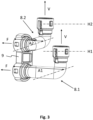
- FIG 3 shows further components of the node elements mentioned.
- These are two so-called connecting elements 8.1, 8.2, which are each designed and intended to be connected to a connecting line section of a main line element (see Figure 2 ) to be detachably connected.
- the connection is made according to the arrows V.
- Both connecting elements 8.1, 8.2 have a (multiple) curvature in order to adapt a direction of the relevant connecting line section to a direction of the relevant fluid connection of a battery module (in Figure 3 not shown).
- the connection to the fluid connections mentioned is made according to the arrows F, also preferably detachable.
- connection ends for connecting to the mentioned connecting line sections are at different height levels H1, H2.
- the mentioned connection ends are also at different lateral distances A1, A2 with respect to the other connection end for connecting to the mentioned fluid connections.
- the two connecting elements 8.1, 8.2 are detachably connected to one another via a separate connecting part 9 and thus advantageously represent a structural unit for handling purposes.
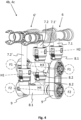
- Figures 4 and 5 show a complete node element 4b, 4c (see Figure 1), which consists of two main line elements 6, 6' (which are also referred to as the first main line element and the second main line element in the context of the present invention) analogous to Figure 2 and four connecting elements 8.1, 8.2 together with the associated connecting parts 9 according to Figure 3
- the two main line elements 6, 6' differ in terms of the length of their respective connecting line sections 7.1, 7.2 and 7.1', 7.2 ⁇ ; the main line element 6 corresponds to Figure 4 and Figure 5 exactly the main line element 6 from Figure 2 (with relatively short connecting line sections 7.1, 7.2), while the other main line element 6', in contrast, has longer connecting line sections 7.1', 7.2'.
- the connecting line sections 7.1, 7.2, which branch off from the first main line element 6, are also referred to here as first connecting line sections, while the connecting line sections 7.1', 7.2', which branch off from the second main line element 6', are also referred to as second connecting line sections.
- the main line elements 6, 6' are arranged parallel to each other - in particular as regards the extension of the respective connecting line sections 7.1, 7.2 or 7.1', 7.2'.
- the connecting elements 8.1, 8.2 are each as shown in Figure 3 combined into a common, manageable component or a corresponding arrangement, whereby in the rear part of the In the arrangement in both figures, the connecting elements 8.1, 8.2 are arranged interchangeably between top and bottom.
- the main line element 6 engages with its two (short) connecting line sections 7.1, 7.2 at the same height level H2 and at the same lateral distance (not designated) in those connecting elements 8.1, 8.2 that are intended for a connection to the respective upper fluid connection of two battery modules arranged opposite one another (not shown).
- the main line element 6' engages with its two (long) connecting line sections 7.1', 7.2' at the same height level H1 and at the same lateral distance (not designated) in those connecting elements 8.1, 8.2 that are intended for a connection to the respective lower fluid connection of two battery modules arranged opposite one another (not shown).
- the connecting elements 8.1, 8.2 connected to the (first) main line element 6 are also referred to as first connecting elements in the present case, while the connecting elements 8.1, 8.2 connected to the (second) main line element 6' are also referred to as second connecting elements in the present case.
- the two first connecting elements are therefore designed differently, and the two second connecting elements also have a different design.
- the one first connecting element 8.1 and the other first connecting element 8.2 each have a connection structure for a battery module or for a corresponding fluid connection at one end, which connection structures are arranged at the same (first) height level H3.
- the one second connecting element 8.1 and the other second connecting element 8.2 each also have a connection structure for a battery module or for a corresponding fluid connection at one end, which connection structures are arranged at the same (second) height level H4, wherein the first height level H3 and the second height level H4 are different.
- both are connected to the main line element 6, whereas the two lower fluid connections (for discharging tempering fluid) are connected to the main line element 6'.
- Reference symbol F1 designates the first, upper fluid connection with height level H3
- reference symbol F2 designates the second, lower fluid connection (with height level H4).
- the detachable connections mentioned in the area of the connecting elements 8.1, 8.2 are preferably plug-in/snap-in connections, as shown, which interact with corresponding projections on the connecting line sections 7.1, 7.2 or 7.1', 7.2'.
- the connecting elements 8.1, 8.2 can first be connected in pairs to the two fluid connections of a respective battery module (each connecting element 8.1, 8.2 with one fluid connection).
- the main line elements 6, 6' are then inserted from above with their respective connecting line sections 7.1, 7.2 or 7.1', 7.2' into the associated connection ends.
- the main line elements 6, 6' can then be connected in a fluid-conducting manner to further main line elements of further node elements in order to create a complete fluid distribution system.
- Figure 6 A slightly modified node element is shown, which corresponds to the node element 4a from Figure 1 It differs from the node element according to the Figures 4 and 5 only because not only two, but four connecting line sections 7.1, 7.2 (only partially designated for reasons of clarity) branch off from the respective main line element 6, 6'. In between there is again a flexible line section 6a, 6a'.
- the number of connecting elements 8.1, 8.2 used (in Figure 6 not marked) compared to the representation in the Figures 4 and 5 doubled.
- Figure 7 and Figure 8 is based on the representation in Figure 1 shown how a fluid distribution system 4 according to the invention can be used to compensate for height differences between the battery modules used due to the flexible line elements 5 used. The same applies to lateral offset (not shown).
- the flexible line elements 5 used in particular enable the replacement of individual battery modules without dismantling the entire fluid distribution system 4.
- the battery modules 2.1-2.6 are specifically designed according to Figure 7 arranged in a configuration in a common plane E.
- the connecting elements and/or the main line elements are preferably introduced perpendicular to the plane E in the direction of the arrow -Z from above into an area between the opposing battery modules 2.1-2.6.
- the connection is then made in the transverse direction by means of the flexible line elements 5.
- the invention is not limited to use in battery modules with fluid connections arranged one above the other. If the fluid connections are located next to each other or otherwise offset, the person skilled in the art will specifically adapt a (curved) geometry of the connecting elements in order to be able to further utilize the particular advantages of the invention.
- first and second main line elements are identical parts, ie with branch line sections of the same length.
- a corresponding adaptation of the connecting elements may be necessary, which may thus will be different in each case, as the expert will easily recognize. The costs and benefits of such a modification must be weighed accordingly.
Landscapes
- Engineering & Computer Science (AREA)
- Manufacturing & Machinery (AREA)
- Chemical & Material Sciences (AREA)
- Chemical Kinetics & Catalysis (AREA)
- Electrochemistry (AREA)
- General Chemical & Material Sciences (AREA)
- Filling, Topping-Up Batteries (AREA)
- Connection Of Batteries Or Terminals (AREA)
- Battery Mounting, Suspending (AREA)
- Quick-Acting Or Multi-Walled Pipe Joints (AREA)
Applications Claiming Priority (2)
| Application Number | Priority Date | Filing Date | Title |
|---|---|---|---|
| DE102022114847.5A DE102022114847A1 (de) | 2022-06-13 | 2022-06-13 | Fluidverteilungssystem, Batteriemodulanordnung und Verfahren zum fluidleitenden Verbinden von Batteriemodulen in einer Batteriemodulanordnung |
| EP23176773.2A EP4293799A1 (fr) | 2022-06-13 | 2023-06-01 | Système de distribution de fluide, ensemble module de batterie et procédé de connexion de manière fluidique de modules de batterie dans un ensemble module de batterie |
Related Parent Applications (1)
| Application Number | Title | Priority Date | Filing Date |
|---|---|---|---|
| EP23176773.2A Division EP4293799A1 (fr) | 2022-06-13 | 2023-06-01 | Système de distribution de fluide, ensemble module de batterie et procédé de connexion de manière fluidique de modules de batterie dans un ensemble module de batterie |
Publications (3)
| Publication Number | Publication Date |
|---|---|
| EP4401203A2 true EP4401203A2 (fr) | 2024-07-17 |
| EP4401203A3 EP4401203A3 (fr) | 2024-09-04 |
| EP4401203B1 EP4401203B1 (fr) | 2025-07-30 |
Family
ID=86657289
Family Applications (3)
| Application Number | Title | Priority Date | Filing Date |
|---|---|---|---|
| EP23176773.2A Pending EP4293799A1 (fr) | 2022-06-13 | 2023-06-01 | Système de distribution de fluide, ensemble module de batterie et procédé de connexion de manière fluidique de modules de batterie dans un ensemble module de batterie |
| EP24172515.9A Active EP4401202B1 (fr) | 2022-06-13 | 2023-06-01 | Système de distribution de fluide, ensemble module de batterie et procédé de connexion de manière fluidique de modules de batterie dans un ensemble module de batterie |
| EP24172520.9A Active EP4401203B1 (fr) | 2022-06-13 | 2023-06-01 | Système de distribution de fluide, ensemble module de batterie et procédé de connexion de manière fluidique de modules de batterie dans un ensemble module de batterie |
Family Applications Before (2)
| Application Number | Title | Priority Date | Filing Date |
|---|---|---|---|
| EP23176773.2A Pending EP4293799A1 (fr) | 2022-06-13 | 2023-06-01 | Système de distribution de fluide, ensemble module de batterie et procédé de connexion de manière fluidique de modules de batterie dans un ensemble module de batterie |
| EP24172515.9A Active EP4401202B1 (fr) | 2022-06-13 | 2023-06-01 | Système de distribution de fluide, ensemble module de batterie et procédé de connexion de manière fluidique de modules de batterie dans un ensemble module de batterie |
Country Status (4)
| Country | Link |
|---|---|
| US (1) | US20230402679A1 (fr) |
| EP (3) | EP4293799A1 (fr) |
| CN (1) | CN117239283A (fr) |
| DE (1) | DE102022114847A1 (fr) |
Families Citing this family (3)
| Publication number | Priority date | Publication date | Assignee | Title |
|---|---|---|---|---|
| DE102023126089A1 (de) * | 2023-09-26 | 2025-03-27 | Voss Automotive Gmbh | "Fluidverteileranordnung eines Temperierkreislaufes" |
| DE102024112888A1 (de) * | 2024-05-08 | 2025-11-13 | Voss Automotive Gmbh | Konnektorblock für eine Fluidleitungsstruktur sowie Fluidleitungsstruktur eines modularen Temperiersystems |
| DE102024130887A1 (de) * | 2024-10-23 | 2026-04-23 | Mahle International Gmbh | Temperiersystem |
Citations (1)
| Publication number | Priority date | Publication date | Assignee | Title |
|---|---|---|---|---|
| CN207690952U (zh) | 2017-09-05 | 2018-08-03 | 崔中华 | 一种流道板及方形电芯冷却液循环系统 |
Family Cites Families (11)
| Publication number | Priority date | Publication date | Assignee | Title |
|---|---|---|---|---|
| GB714824A (en) | 1952-04-04 | 1954-09-01 | Tudor Ab | Improvements in or relating to connecting and cooling arrangements in electric storage batteries |
| EP2744033B1 (fr) | 2012-12-07 | 2015-02-18 | Obrist Powertrain GmbH | Batterie |
| CN205882124U (zh) * | 2016-08-03 | 2017-01-11 | 弗兰科希管件系统(上海)有限公司 | 电池包冷却液集成管路 |
| CN107293769B (zh) * | 2017-07-22 | 2023-06-16 | 江阴标榜汽车部件股份有限公司 | 用于新能源汽车上的电池冷却管路总成 |
| WO2019046012A1 (fr) * | 2017-08-30 | 2019-03-07 | Modine Manufacturing Company | Système de refroidissement de batterie |
| DE102018110528A1 (de) | 2018-05-02 | 2019-11-07 | Witzenmann Gmbh | Kontaktier- und Temperiereinrichtung für eine Batteriezelle, Batteriezelle, Batterieanordnung und Verfahren zu deren Kontaktierung und Temperierung |
| DE102018210444B3 (de) * | 2018-06-27 | 2019-05-09 | Bayerische Motoren Werke Aktiengesellschaft | Hochvoltbatterie für ein Kraftfahrzeug sowie Kraftfahrzeug |
| US11721856B2 (en) * | 2018-10-12 | 2023-08-08 | Samsung Sdi Co., Ltd. | Battery pack for a vehicle |
| JP6830980B2 (ja) * | 2019-05-16 | 2021-02-17 | 本田技研工業株式会社 | 車両用バッテリユニットの冷却構造 |
| CN212584519U (zh) * | 2020-06-17 | 2021-02-23 | 弗兰科希管件系统(上海)有限公司 | 冷却液输送装置及电池包冷却系统 |
| CN214254542U (zh) * | 2021-03-24 | 2021-09-21 | 河北机电职业技术学院 | 一种新能源汽车电池冷却系统 |
-
2022
- 2022-06-13 DE DE102022114847.5A patent/DE102022114847A1/de active Pending
-
2023
- 2023-05-12 US US18/316,603 patent/US20230402679A1/en active Pending
- 2023-05-31 CN CN202310640914.3A patent/CN117239283A/zh active Pending
- 2023-06-01 EP EP23176773.2A patent/EP4293799A1/fr active Pending
- 2023-06-01 EP EP24172515.9A patent/EP4401202B1/fr active Active
- 2023-06-01 EP EP24172520.9A patent/EP4401203B1/fr active Active
Patent Citations (1)
| Publication number | Priority date | Publication date | Assignee | Title |
|---|---|---|---|---|
| CN207690952U (zh) | 2017-09-05 | 2018-08-03 | 崔中华 | 一种流道板及方形电芯冷却液循环系统 |
Also Published As
| Publication number | Publication date |
|---|---|
| EP4401202B1 (fr) | 2026-02-04 |
| EP4401202A2 (fr) | 2024-07-17 |
| EP4293799A1 (fr) | 2023-12-20 |
| EP4401202A3 (fr) | 2024-09-04 |
| US20230402679A1 (en) | 2023-12-14 |
| DE102022114847A1 (de) | 2023-12-14 |
| CN117239283A (zh) | 2023-12-15 |
| EP4401203A3 (fr) | 2024-09-04 |
| EP4401203B1 (fr) | 2025-07-30 |
Similar Documents
| Publication | Publication Date | Title |
|---|---|---|
| EP4401203B1 (fr) | Système de distribution de fluide, ensemble module de batterie et procédé de connexion de manière fluidique de modules de batterie dans un ensemble module de batterie | |
| DE202014105615U1 (de) | Tragachse für Photovoltaikmodule und Anlage mit mehreren Photovoltaikmodulen | |
| DE102019126101A1 (de) | Anschlussblock für einen Motor und Verfahren zu dessen Herstellung | |
| DE102009015542A1 (de) | Bidirektionale Kabelschuhverbindung und Verfahren | |
| EP3954006B1 (fr) | Agencement d'armoire électrique avec une ossature et un module de protection contre les contacts multipolaire monté sur une platine de montage | |
| DE69507450T2 (de) | Modulare elektrische Reihenklemmenanordnung | |
| WO2013135467A1 (fr) | Unité de montage et procédé de montage d'un rail de montage sur une plaque de montage pour une armoire électrique | |
| EP0261544A1 (fr) | Assemblage de combustible pour réacteur nucléaire | |
| DE19901962B4 (de) | Verfahren zum Montieren elektrischer Steckverbindungen sowie Montagehilfe zur Verfahrensdurchführung | |
| EP3396799B1 (fr) | Dispositif de traversée | |
| EP4098506A1 (fr) | Transition entre deux parties de véhicule dotée d'un dispositif de connexion électrique | |
| DE102007011986A1 (de) | Anzeigevorrichtung mit Halteelement | |
| DE3718693A1 (de) | Buchsenfoermiges spritzguss-bauteil, insbesondere waelzlagerkaefig | |
| DE102017203547B4 (de) | Steckverbinder und Verfahren zur Herstellung eines Steckverbinders | |
| WO2012025262A1 (fr) | Convertisseur basculant à suspension à baguettes pendulaires | |
| EP1381118A1 (fr) | Connecteur symétrique | |
| EP0709252A1 (fr) | Faisceau de câbles en particulier pour le montage dans une carosserie de voiture | |
| DE102005035247A1 (de) | Fluidverteiler mit binärer Struktur | |
| DE3045520C2 (de) | Zweiteilige Leitungsschelle | |
| DE4435488A1 (de) | Verfahren und Vorrichtung zum Auswechseln eines Knotenbleches | |
| EP3636363A2 (fr) | Module d'outil pour une installation d'outil à suivre | |
| DE69711200T2 (de) | Sammelschienenträger | |
| EP3678268A1 (fr) | Cadre pour une cellule de production | |
| DE2114189C3 (de) | Leitungsverteiler, insbesondere Rangierverteiler | |
| DE102019118386A1 (de) | Steckverbindergehäuse |
Legal Events
| Date | Code | Title | Description |
|---|---|---|---|
| PUAI | Public reference made under article 153(3) epc to a published international application that has entered the european phase |
Free format text: ORIGINAL CODE: 0009012 |
|
| STAA | Information on the status of an ep patent application or granted ep patent |
Free format text: STATUS: THE APPLICATION HAS BEEN PUBLISHED |
|
| AC | Divisional application: reference to earlier application |
Ref document number: 4293799 Country of ref document: EP Kind code of ref document: P |
|
| AK | Designated contracting states |
Kind code of ref document: A2 Designated state(s): AL AT BE BG CH CY CZ DE DK EE ES FI FR GB GR HR HU IE IS IT LI LT LU LV MC ME MK MT NL NO PL PT RO RS SE SI SK SM TR |
|
| PUAL | Search report despatched |
Free format text: ORIGINAL CODE: 0009013 |
|
| AK | Designated contracting states |
Kind code of ref document: A3 Designated state(s): AL AT BE BG CH CY CZ DE DK EE ES FI FR GB GR HR HU IE IS IT LI LT LU LV MC ME MK MT NL NO PL PT RO RS SE SI SK SM TR |
|
| RIC1 | Information provided on ipc code assigned before grant |
Ipc: H01M 10/6568 20140101AFI20240731BHEP |
|
| STAA | Information on the status of an ep patent application or granted ep patent |
Free format text: STATUS: REQUEST FOR EXAMINATION WAS MADE |
|
| 17P | Request for examination filed |
Effective date: 20241015 |
|
| RBV | Designated contracting states (corrected) |
Designated state(s): AL AT BE BG CH CY CZ DE DK EE ES FI FR GB GR HR HU IE IS IT LI LT LU LV MC ME MK MT NL NO PL PT RO RS SE SI SK SM TR |
|
| GRAP | Despatch of communication of intention to grant a patent |
Free format text: ORIGINAL CODE: EPIDOSNIGR1 |
|
| STAA | Information on the status of an ep patent application or granted ep patent |
Free format text: STATUS: GRANT OF PATENT IS INTENDED |
|
| INTG | Intention to grant announced |
Effective date: 20250123 |
|
| GRAS | Grant fee paid |
Free format text: ORIGINAL CODE: EPIDOSNIGR3 |
|
| GRAA | (expected) grant |
Free format text: ORIGINAL CODE: 0009210 |
|
| STAA | Information on the status of an ep patent application or granted ep patent |
Free format text: STATUS: THE PATENT HAS BEEN GRANTED |
|
| AC | Divisional application: reference to earlier application |
Ref document number: 4293799 Country of ref document: EP Kind code of ref document: P |
|
| AK | Designated contracting states |
Kind code of ref document: B1 Designated state(s): AL AT BE BG CH CY CZ DE DK EE ES FI FR GB GR HR HU IE IS IT LI LT LU LV MC ME MK MT NL NO PL PT RO RS SE SI SK SM TR |
|
| REG | Reference to a national code |
Ref country code: GB Ref legal event code: FG4D Free format text: NOT ENGLISH |
|
| REG | Reference to a national code |
Ref country code: CH Ref legal event code: EP |
|
| REG | Reference to a national code |
Ref country code: DE Ref legal event code: R096 Ref document number: 502023001486 Country of ref document: DE |
|
| REG | Reference to a national code |
Ref country code: IE Ref legal event code: FG4D Free format text: LANGUAGE OF EP DOCUMENT: GERMAN |
|
| REG | Reference to a national code |
Ref country code: NL Ref legal event code: MP Effective date: 20250730 |
|
| PG25 | Lapsed in a contracting state [announced via postgrant information from national office to epo] |
Ref country code: PT Free format text: LAPSE BECAUSE OF FAILURE TO SUBMIT A TRANSLATION OF THE DESCRIPTION OR TO PAY THE FEE WITHIN THE PRESCRIBED TIME-LIMIT Effective date: 20251202 |
|
| PG25 | Lapsed in a contracting state [announced via postgrant information from national office to epo] |
Ref country code: IS Free format text: LAPSE BECAUSE OF FAILURE TO SUBMIT A TRANSLATION OF THE DESCRIPTION OR TO PAY THE FEE WITHIN THE PRESCRIBED TIME-LIMIT Effective date: 20251130 |
|
| PG25 | Lapsed in a contracting state [announced via postgrant information from national office to epo] |
Ref country code: NO Free format text: LAPSE BECAUSE OF FAILURE TO SUBMIT A TRANSLATION OF THE DESCRIPTION OR TO PAY THE FEE WITHIN THE PRESCRIBED TIME-LIMIT Effective date: 20251030 |
|
| REG | Reference to a national code |
Ref country code: LT Ref legal event code: MG9D |
|
| PG25 | Lapsed in a contracting state [announced via postgrant information from national office to epo] |
Ref country code: FI Free format text: LAPSE BECAUSE OF FAILURE TO SUBMIT A TRANSLATION OF THE DESCRIPTION OR TO PAY THE FEE WITHIN THE PRESCRIBED TIME-LIMIT Effective date: 20250730 |
|
| PG25 | Lapsed in a contracting state [announced via postgrant information from national office to epo] |
Ref country code: HR Free format text: LAPSE BECAUSE OF FAILURE TO SUBMIT A TRANSLATION OF THE DESCRIPTION OR TO PAY THE FEE WITHIN THE PRESCRIBED TIME-LIMIT Effective date: 20250730 Ref country code: NL Free format text: LAPSE BECAUSE OF FAILURE TO SUBMIT A TRANSLATION OF THE DESCRIPTION OR TO PAY THE FEE WITHIN THE PRESCRIBED TIME-LIMIT Effective date: 20250730 |
|
| PG25 | Lapsed in a contracting state [announced via postgrant information from national office to epo] |
Ref country code: GR Free format text: LAPSE BECAUSE OF FAILURE TO SUBMIT A TRANSLATION OF THE DESCRIPTION OR TO PAY THE FEE WITHIN THE PRESCRIBED TIME-LIMIT Effective date: 20251031 |
|
| PG25 | Lapsed in a contracting state [announced via postgrant information from national office to epo] |
Ref country code: SE Free format text: LAPSE BECAUSE OF FAILURE TO SUBMIT A TRANSLATION OF THE DESCRIPTION OR TO PAY THE FEE WITHIN THE PRESCRIBED TIME-LIMIT Effective date: 20250730 |
|
| PG25 | Lapsed in a contracting state [announced via postgrant information from national office to epo] |
Ref country code: LV Free format text: LAPSE BECAUSE OF FAILURE TO SUBMIT A TRANSLATION OF THE DESCRIPTION OR TO PAY THE FEE WITHIN THE PRESCRIBED TIME-LIMIT Effective date: 20250730 |
|
| PG25 | Lapsed in a contracting state [announced via postgrant information from national office to epo] |
Ref country code: BG Free format text: LAPSE BECAUSE OF FAILURE TO SUBMIT A TRANSLATION OF THE DESCRIPTION OR TO PAY THE FEE WITHIN THE PRESCRIBED TIME-LIMIT Effective date: 20250730 Ref country code: PL Free format text: LAPSE BECAUSE OF FAILURE TO SUBMIT A TRANSLATION OF THE DESCRIPTION OR TO PAY THE FEE WITHIN THE PRESCRIBED TIME-LIMIT Effective date: 20250730 |
|
| PG25 | Lapsed in a contracting state [announced via postgrant information from national office to epo] |
Ref country code: RS Free format text: LAPSE BECAUSE OF FAILURE TO SUBMIT A TRANSLATION OF THE DESCRIPTION OR TO PAY THE FEE WITHIN THE PRESCRIBED TIME-LIMIT Effective date: 20251030 |
|
| PG25 | Lapsed in a contracting state [announced via postgrant information from national office to epo] |
Ref country code: ES Free format text: LAPSE BECAUSE OF FAILURE TO SUBMIT A TRANSLATION OF THE DESCRIPTION OR TO PAY THE FEE WITHIN THE PRESCRIBED TIME-LIMIT Effective date: 20250730 |
|
| PG25 | Lapsed in a contracting state [announced via postgrant information from national office to epo] |
Ref country code: SM Free format text: LAPSE BECAUSE OF FAILURE TO SUBMIT A TRANSLATION OF THE DESCRIPTION OR TO PAY THE FEE WITHIN THE PRESCRIBED TIME-LIMIT Effective date: 20250730 |
|
| PG25 | Lapsed in a contracting state [announced via postgrant information from national office to epo] |
Ref country code: DK Free format text: LAPSE BECAUSE OF FAILURE TO SUBMIT A TRANSLATION OF THE DESCRIPTION OR TO PAY THE FEE WITHIN THE PRESCRIBED TIME-LIMIT Effective date: 20250730 |
|
| PG25 | Lapsed in a contracting state [announced via postgrant information from national office to epo] |
Ref country code: IT Free format text: LAPSE BECAUSE OF FAILURE TO SUBMIT A TRANSLATION OF THE DESCRIPTION OR TO PAY THE FEE WITHIN THE PRESCRIBED TIME-LIMIT Effective date: 20250730 |
|
| PG25 | Lapsed in a contracting state [announced via postgrant information from national office to epo] |
Ref country code: CZ Free format text: LAPSE BECAUSE OF FAILURE TO SUBMIT A TRANSLATION OF THE DESCRIPTION OR TO PAY THE FEE WITHIN THE PRESCRIBED TIME-LIMIT Effective date: 20250730 |
|
| PG25 | Lapsed in a contracting state [announced via postgrant information from national office to epo] |
Ref country code: SK Free format text: LAPSE BECAUSE OF FAILURE TO SUBMIT A TRANSLATION OF THE DESCRIPTION OR TO PAY THE FEE WITHIN THE PRESCRIBED TIME-LIMIT Effective date: 20250730 Ref country code: EE Free format text: LAPSE BECAUSE OF FAILURE TO SUBMIT A TRANSLATION OF THE DESCRIPTION OR TO PAY THE FEE WITHIN THE PRESCRIBED TIME-LIMIT Effective date: 20250730 |