EP4401300A1 - Évaluation du facteur de réduction rotor-stator pour machines synchrones à excitation externe - Google Patents
Évaluation du facteur de réduction rotor-stator pour machines synchrones à excitation externe Download PDFInfo
- Publication number
- EP4401300A1 EP4401300A1 EP23151482.9A EP23151482A EP4401300A1 EP 4401300 A1 EP4401300 A1 EP 4401300A1 EP 23151482 A EP23151482 A EP 23151482A EP 4401300 A1 EP4401300 A1 EP 4401300A1
- Authority
- EP
- European Patent Office
- Prior art keywords
- stator
- current
- value
- rotor
- excitation current
- Prior art date
- Legal status (The legal status is an assumption and is not a legal conclusion. Google has not performed a legal analysis and makes no representation as to the accuracy of the status listed.)
- Pending
Links
Images
Classifications
-
- H—ELECTRICITY
- H02—GENERATION; CONVERSION OR DISTRIBUTION OF ELECTRIC POWER
- H02P—CONTROL OR REGULATION OF ELECTRIC MOTORS, ELECTRIC GENERATORS OR DYNAMO-ELECTRIC CONVERTERS; CONTROLLING TRANSFORMERS, REACTORS OR CHOKE COILS
- H02P27/00—Arrangements or methods for the control of AC motors characterised by the kind of supply voltage
- H02P27/04—Arrangements or methods for the control of AC motors characterised by the kind of supply voltage using variable-frequency supply voltage, e.g. inverter or converter supply voltage
- H02P27/05—Arrangements or methods for the control of AC motors characterised by the kind of supply voltage using variable-frequency supply voltage, e.g. inverter or converter supply voltage using AC supply for both the rotor and the stator circuits, the frequency of supply to at least one circuit being variable
-
- H—ELECTRICITY
- H02—GENERATION; CONVERSION OR DISTRIBUTION OF ELECTRIC POWER
- H02P—CONTROL OR REGULATION OF ELECTRIC MOTORS, ELECTRIC GENERATORS OR DYNAMO-ELECTRIC CONVERTERS; CONTROLLING TRANSFORMERS, REACTORS OR CHOKE COILS
- H02P21/00—Arrangements or methods for the control of electric machines by vector control, e.g. by control of field orientation
- H02P21/22—Current control, e.g. using a current control loop
-
- H—ELECTRICITY
- H02—GENERATION; CONVERSION OR DISTRIBUTION OF ELECTRIC POWER
- H02P—CONTROL OR REGULATION OF ELECTRIC MOTORS, ELECTRIC GENERATORS OR DYNAMO-ELECTRIC CONVERTERS; CONTROLLING TRANSFORMERS, REACTORS OR CHOKE COILS
- H02P1/00—Arrangements for starting electric motors or dynamo-electric converters
- H02P1/02—Details of starting control
-
- H—ELECTRICITY
- H02—GENERATION; CONVERSION OR DISTRIBUTION OF ELECTRIC POWER
- H02P—CONTROL OR REGULATION OF ELECTRIC MOTORS, ELECTRIC GENERATORS OR DYNAMO-ELECTRIC CONVERTERS; CONTROLLING TRANSFORMERS, REACTORS OR CHOKE COILS
- H02P21/00—Arrangements or methods for the control of electric machines by vector control, e.g. by control of field orientation
- H02P21/0003—Control strategies in general, e.g. linear type, e.g. P, PI, PID, using robust control
- H02P21/0025—Control strategies in general, e.g. linear type, e.g. P, PI, PID, using robust control implementing a off line learning phase to determine and store useful data for on-line control
-
- H—ELECTRICITY
- H02—GENERATION; CONVERSION OR DISTRIBUTION OF ELECTRIC POWER
- H02P—CONTROL OR REGULATION OF ELECTRIC MOTORS, ELECTRIC GENERATORS OR DYNAMO-ELECTRIC CONVERTERS; CONTROLLING TRANSFORMERS, REACTORS OR CHOKE COILS
- H02P21/00—Arrangements or methods for the control of electric machines by vector control, e.g. by control of field orientation
- H02P21/14—Estimation or adaptation of machine parameters, e.g. flux, current or voltage
-
- H—ELECTRICITY
- H02—GENERATION; CONVERSION OR DISTRIBUTION OF ELECTRIC POWER
- H02P—CONTROL OR REGULATION OF ELECTRIC MOTORS, ELECTRIC GENERATORS OR DYNAMO-ELECTRIC CONVERTERS; CONTROLLING TRANSFORMERS, REACTORS OR CHOKE COILS
- H02P21/00—Arrangements or methods for the control of electric machines by vector control, e.g. by control of field orientation
- H02P21/24—Vector control not involving the use of rotor position or rotor speed sensors
- H02P21/28—Stator flux based control
-
- H—ELECTRICITY
- H02—GENERATION; CONVERSION OR DISTRIBUTION OF ELECTRIC POWER
- H02P—CONTROL OR REGULATION OF ELECTRIC MOTORS, ELECTRIC GENERATORS OR DYNAMO-ELECTRIC CONVERTERS; CONTROLLING TRANSFORMERS, REACTORS OR CHOKE COILS
- H02P23/00—Arrangements or methods for the control of AC motors characterised by a control method other than vector control
- H02P23/14—Estimation or adaptation of motor parameters, e.g. rotor time constant, flux, speed, current or voltage
-
- H—ELECTRICITY
- H02—GENERATION; CONVERSION OR DISTRIBUTION OF ELECTRIC POWER
- H02P—CONTROL OR REGULATION OF ELECTRIC MOTORS, ELECTRIC GENERATORS OR DYNAMO-ELECTRIC CONVERTERS; CONTROLLING TRANSFORMERS, REACTORS OR CHOKE COILS
- H02P25/00—Arrangements or methods for the control of AC motors characterised by the kind of AC motor or by structural details
- H02P25/02—Arrangements or methods for the control of AC motors characterised by the kind of AC motor or by structural details characterised by the kind of motor
- H02P25/022—Synchronous motors
-
- H—ELECTRICITY
- H02—GENERATION; CONVERSION OR DISTRIBUTION OF ELECTRIC POWER
- H02P—CONTROL OR REGULATION OF ELECTRIC MOTORS, ELECTRIC GENERATORS OR DYNAMO-ELECTRIC CONVERTERS; CONTROLLING TRANSFORMERS, REACTORS OR CHOKE COILS
- H02P2207/00—Indexing scheme relating to controlling arrangements characterised by the type of motor
- H02P2207/05—Synchronous machines, e.g. with permanent magnets or DC excitation
Definitions
- Various example embodiments relate to control of industrial processes.
- the reduction factor (or more specifically the rotor-to-stator reduction factor) is used to refer the rotor excitation current to the stator side.
- the reduction factor is equal for both salient and non-salient pole synchronous machines.
- the reduction factor is calculated from short circuit measurements (i.e., from a short-circuit curve) and from zero-load measurements.
- This calculation typically requires specific data provided by the manufacturer of the synchronous machine. However, this data may not be always available and/or it may be inaccurate leading to an error in the calculated reduction factor.
- Some embodiments provide an apparatus, a method, and computer program for calculating a rotor-to-stator reduction factor.
- circuitry' may refer to one or more or all of the following: (a) hardware-only circuit implementations, such as implementations in only analog and/or digital circuitry, and (b) combinations of hardware circuits and software (and/or firmware), such as (as applicable): (i) a combination of analog and/or digital hardware circuit(s) with software/firmware and (ii) any portions of hardware processor(s) with software, including digital signal processor(s), software, and memory(ies) that work together to cause an apparatus, such as a terminal device or an access node, to perform various functions, and (c) hardware circuit(s) and processor(s), such as a microprocessor(s) or a portion of a microprocessor(s), that requires software (e.g.
- circuitry for operation, but the software may not be present when it is not needed for operation.
- This definition of 'circuitry' applies to all uses of this term in this application, including any claims.
- the term 'circuitry' also covers an implementation of merely a hardware circuit or processor (or multiple processors) or a portion of a hardware circuit or processor and its (or their) accompanying software and/or firmware.
- a per-unit (pu or p.u.) system may be employed for mathematical description of an externally excited synchronous machine.
- the per-unit system is the dimensionless relative value system defined in terms of base values.
- the motor nominal values may be chosen to be the base values in the pu system.
- a synchronous motor (or equally a synchronous machine) is an electric motor where the rotation of the motor shaft (i.e., of the rotor) is synchronized with the frequency of the supply current at steady state so that the rotation period is equal to an integral number of alternating current (AC) cycles.
- AC alternating current
- Externally excited (or externally magnetized) synchronous machines are used in a variety of applications in industry, transportation and utilities sectors.
- the rotor of the synchronous machine is connected to a direct current (DC) power source via a rotating electrical contact called a slip ring and conductive brushes for exciting the rotor (via an excitation current).
- DC direct current
- a brushless exciter may be employed for enabling said DC connection.
- a reduction factor (equally called a rotor-to-stator reduction factor or a reduction factor of the excitation current) is used to refer the rotor excitation current to the stator side.
- the reduction factor may be used for referring a (measured) excitation current (and rotor resistances) to the stator voltage level.
- the reduction factor may be also used for referring an excitation current reference calculated at the stator voltage level to the excitation winding voltage level for excitation unit current control. Accurate estimation of the reduction factor is important as an erroneous reduction factor affects the current model flux estimation, which directly affects the excitation control and torque.
- the rotor excitation current i F may be equally called rotor excitation DC current. Unless otherwise explicitly indicated, the term "rotor excitation current" is used in the following to mean the rotor excitation DC current i F .
- the rotor-to-stator reduction factor is usable by a drive for referring the rotor parameters (e.g., the rotor excitation current and/or resistance) to the stator side (i.e., for calculating stator parameters knowing the associated rotor parameters).
- the reduction factor may be defined in the same manner for both salient pole and non-salient pole synchronous motors (equally called salient and non-salient synchronous motors or machines).
- the reduction factor is either provided in a design document of the synchronous motor or, if no design document is available, calculated based on short-circuit measurements (i.e., from a short-circuit curve) and zero-load measurements. Said calculation typically requires specific data provided by the manufacturer of the synchronous machine. However, this data may not be always available and/or it may be inaccurate leading an error in the calculated reduction factor.
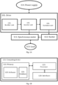
- Figure 1A illustrates a system to which embodiments of the invention may be applied.
- Figure 1A illustrates simplified system architecture only showing some elements and functional entities (namely, showing only some excitation control related elements and functional entities), all being logical units whose implementation may differ from what is shown.
- the connections shown in Figure 1A are logical connections; the actual physical connections may be different. It is apparent to a person skilled in the art that the system may also comprise other functions and structures.
- FIG. 1A illustrates a system comprising a drive 101 (equally called a motor drive) controlling a synchronous motor 111.
- the drive 101 is powered by a power supply 114.
- the synchronous motor 111 may be specifically an externally excited synchronous motor 111 with the external excitation being provided by the exciter 112 (e.g., a slip ring with conductive brushes or a brushless exciter) which is controlled or driven by the drive 101 (or specifically by the excitation unit 104 therein).
- the illustrated system (or specifically the drive 101) may be configured to operate using direct torque control (DTC), current vector control or any other control scheme for motor drives.
- the synchronous motor 111 may be salient pole or non-salient pole.
- the synchronous motor 111 (or equally the synchronous machine 111) is connected to a mechanical load 113.
- the mechanical load 113 may correspond, for example, to a device or a system for transporting material, such as a pump, a fan, a compressor, a blower, a conveyor belt, a crane and/or an elevator and/or a device or a system for processing materials, such as a paper machine, a mill, a stirrer and/or a centrifuge.
- the drive 101 is a device used for controlling the motion of the synchronous motor 111 (or a synchronous machine). Said control may be achieved by changing one or more drive parameters of the drive 101 which may comprise parameters such as torque, speed, power, voltage, rotor excitation current, stator flux linkage, frequency, motor control mode (e.g., scalar, vector or direct torque control), proportional-integral-derivative (PID) controller settings, acceleration ramp settings, deceleration ramp settings and/or other parameters affecting the operation of the drive.
- the drive 101 may specifically be an electrical drive (an AC drive supporting low to high voltages and/or low to high motor speeds).
- the drive 101 may be equally called a frequency converter.
- the drive 101 may be a programmable logic controller (PLC) or a (motor) soft starter.
- the drive 101 may be a variable speed drive (VSD) or a variable frequency drive (VFD).
- VSD variable speed drive
- VFD variable frequency drive
- the drive 101 (or specifically the inverter unit 103) feeds the synchronous motor 111 via a three-phase power supply. Contrary to some definitions of term "drive”, the synchronous motor 111 which is driven by the drive 101 does not form a part of the drive 101 itself in the context of this application (as is also shown in Figure 1A ).
- the drive 101 comprises a rectifier unit 102 for connecting to the alternating current (AC) power supply 114 and converting the AC power to DC power.
- AC alternating current
- the drive 101 comprises an inverter unit 103 for converting the DC power provided by the rectifier unit 102 to AC power for driving the synchronous motor 111 in a controlled manner.
- the inverter unit 103 is configured to feed the stator winding of the synchronous motor 111 to control the operation of the synchronous motor 111 (e.g., the air gap torque and the stator flux linkage).
- the inverter unit 103 is configured to provide stator voltage signals having a particular voltage and frequency to the synchronous motor 111.
- the control of the synchronous motor 111 may be provided using, e.g., DTC or current vector control or scalar control.
- the rectifier and inverter units 102, 103 may be connected together via a direct current (DC) circuit (equally called a DC link) which may comprise, for example, at least one DC choke and/or one or more capacitors (not shown in Figure 1A ).
- DC direct current
- the rectifier and inverter units 102, 103 effectively form together a DC link converter (unit) for performing a two-phase frequency conversion from the AC power of the AC power supply 114 to DC power and from said DC power to AC power suitable for driving the synchronous motor 111 in a controlled manner.
- a single-phase frequency conversion may be employed in the drive 101, instead of the two-phase frequency conversion.
- a (single) direct converter unit may be provided instead of the rectifier and inverter units 102, 103 (and the DC link between them).
- the embodiments for calculating a reduction factor to be discussed below in detail may be implemented specifically in a converter of the drive 101 such as in the rectifier unit 102 and/or in the inverter unit 103.
- the drive 101 comprises an excitation unit for providing an external DC excitation for a rotor of the synchronous machine 111 (i.e., for an excitation winding of the synchronous machine 111).
- the external excitation may be provided to the excitation winding via an exciter 112 such as a rotary electrical contact (also called a split ring or an electrical slip ring).
- the excitation unit 104 may be configured to be controlled by the inverter unit 103.
- the inverter unit 103 may be configured to calculate an excitation winding current that would produce unity power factor (or other desired power factor) in the steady state and to provide the calculated value as an excitation (or field) current reference to the excitation unit 104.
- the drive 101 may further comprise one or more user input devices (e.g., a control panel or a touch screen) for enabling the user to control the operation of the drive 101.
- user input devices e.g., a control panel or a touch screen
- the drive 101 may be configured to monitor one or more drive parameters of the drive 101 and/or one or more motor parameters of the synchronous motor 111.
- the drive 101 may monitor, for example, values of the stator flux linkage reference (or stator flux reference), the rotor excitation current reference, the torque reference and/or the stator flux linkage load angle reference.
- stator flux linkage and optionally the rotor excitation current reference and/or the stator current may be monitored.
- the drive 101 may be configured to control the externally-excited synchronous motor 111 using any conventional control scheme.
- one common way which may be employed by the drive 101 for controlling the externally-excited synchronous motor 111 is the so-called vector control where the torque of the motor 111 is controlled by controlling a stator current and/or voltage vector.
- the stator current/voltage vector is a vector comprising two orthogonal stator current/voltage components derived from stator currents/voltages of a three-phase AC electric machine. One of said components defines the magnetic flux of the motor, the other the torque of the motor.
- stator current/voltage components may be written either in a stationary reference frame as ⁇ - and ⁇ -axis stator currents/voltages or in a rotation reference frame (moving in sync with the rotor) as d- and q-axis stator currents/voltages, respectively.
- the actual control in the vector control is typically performed for the d- and q-axis stator currents or voltages.
- the d- and q-axis currents/voltages may be converted to the ⁇ - and ⁇ -axis currents/voltages using inverse Park transform while an opposite transformation is possible using Park transform.
- DTC Direct Torque Control
- DFLC direct flux linkage control
- the current model may be specifically based on measured stator currents and motor inductance parameters.
- the torque of the synchronous motor can be changed by accelerating rotational speed of the stator flux linkage vector.
- Figure 1A illustrates a single synchronous motor 111, in other embodiments the drive 101 may be used for controlling an electrical machine comprising multiple synchronous motors or machines.
- Figure 1B illustrates a computing device 121 which may form a part of a drive such as the drive 101 of Figure 1A or be at least communicatively connected to said drive.
- the computing device 121 may form a part of a converter (or a converter unit) of the drive 101 or may be at least communicatively connected to it.
- Said converter may be, e.g., a rectifier 102 or an inverter 103 of a DC link converter of the drive 101 or a direct converter of a drive.
- the computing device may be configured to at least cause operations necessary for calculating the rotor-to-stator reduction factor as will be described below in detail.
- the computing device 121 comprises a processor 123, interfaces 124 and a memory 122.
- the processor 123 may be a central processing unit (CPU) of the drive 101.
- one or more control circuitry such as one or more processors may be provided in the computing device 121, instead of a singular processor 123.
- the computing device 121 may comprise one or more control circuitry 123, such as at least one processor, and at least one memory 122, including one or more algorithms 125, such as a computer program code (software), wherein the at least one memory 122 and the computer program code (software) are configured, with the at least one processor, to cause the computing device 121 to carry out any one of the exemplified functionalities of the computing device or the drive to be described below. It is also feasible to use specific integrated circuits, such as ASIC (Application Specific Integrated Circuit) or other components and devices for implementing the functionalities in accordance with different embodiments.
- ASIC Application Specific Integrated Circuit
- the memory 122 of the computing device 121 may be implemented using any suitable data storage technology, such as semiconductor based memory devices, flash memory, magnetic memory devices and systems, optical memory devices and systems, fixed memory and removable memory.
- the memory 122 comprises at least one database 126 and software 125 (i.e., one or more algorithms).
- the interfaces 124 of the computing device 121 may comprise, for example, one or more communication interfaces comprising hardware and/or software for realizing communication connectivity according to one or more communication protocols.
- the one or more communication interfaces 124 may comprise, for example, at least one interface providing a connection to an excitation unit.
- the one or more communication interfaces 104 may comprise standard well-known components such as an amplifier, filter, frequency-converter, (de)modulator, and encoder/decoder circuitries, controlled by the corresponding controlling units, and one or more antennas.
- the one or more communication interfaces 124 may also comprise a user interface.
- ⁇ sd L s ⁇ i d + L md i f + i sd + i D
- ⁇ sq L s ⁇ i q + L mq i sq + i Q
- ⁇ sd is a d-axis stator flux linkage
- ⁇ sq is a q-axis stator flux
- L s ⁇ is a stator leakage inductance
- i sd is a d-axis stator current
- i sq is a q-axis stator current
- L md is the d-axis magnetizing inductance
- L mq is the q-axis magnetizing inductance
- i D is a d-axis damper winding current
- L md ⁇ s ,0 k r i F ,0 , where i F,0 is the rotor excitation (DC) current magnitude under zero-load conditions.
- i F,0 the rotor excitation (DC) current magnitude under zero-load conditions.
- stator excitation current i F When the rotor excitation current i F is increased relative to the zero-load value of the rotor excitation current i F,0 , the current will again flow to the stator winding (i.e., the magnitude of the stator current i s will increase and become non-zero).
- i sd ⁇ i s .
- Either of the equations (13)-(14) may be employed by the drive for calculating the rotor-to-stator reduction factor.
- the drive needs to first somehow obtain values of ⁇ s,0 , ⁇ s , i F,0 , i s and i F . How these values may be obtained is discussed in the following.
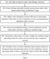
- Figure 2 illustrates a process according to embodiments for calculating the rotor-to-stator reduction factor of an externally excited synchronous motor.
- the process may be carried out by a drive or specifically by a converter of a drive (or another apparatus comprised in the drive).
- the process may be carried out by the drive 101 of Figure 1A (e.g., by the rectifier and/or inverter unit 102, 103 therein) or specifically by the computing device 121 of Figure 1B comprised in the drive 101 (in the rectifier or inverter unit 102, 103 or communicatively connected thereto).
- At least one processor of the computing device of the drive and at least one memory of the computing device of the drive for storing instructions to be executed by the at least one processor may be configured so as to cause the drive to carry out the illustrated process.
- the actor of the process is called “the apparatus" for simplicity.
- the apparatus initially sets, in block 201, a value at least for a stator flux linkage reference ( ⁇ s,ref ) of the externally excited synchronous motor.
- the value for the stator flux linkage reference may be selected to be relatively small. Namely, the value of the stator flux linkage reference may be selected to be small enough to enable operation in a (substantially) linear region of a d-axis magnetizing inductance ( L md ) of the externally excited synchronous motor without saturation.
- Said linear region may be defined as a region where the magnetizing flux (linkage) ( ⁇ md ) and the magnetizing current ( i md ) have a linear relationship, that is, the magnetizing flux (linkage) changes in a linear manner with the changing magnetizing current.
- the value of the stator flux linkage reference may be selected to be within a range of 0.3 - 0.7 p.u. or within a range of 0.4 - 0.6 p.u., where "p.u.” refers to a per-unit system defined so that 1 p.u. corresponds (substantially) to a nominal stator flux linkage.
- the value of the stator flux linkage reference may be selected to be 0.5 p.u.
- the apparatus may further set, in block 201, an (initial) value for a rotor excitation current reference of the externally excited synchronous motor.
- the initial value for the rotor excitation current reference may be such that the acceleration of the externally excited synchronous motor to the set speed is enabled.
- the initial value for the rotor excitation current reference may be selected to be at least below a nominal rotor excitation current of the externally excited synchronous motor.
- the initial value for the rotor excitation current reference may be read from a pre-defined zero-load curve (equally called a zero-load voltage curve) mapping zero-load voltage against zero-load excitation current.
- the initial value of the rotor excitation current reference may be selected to be smaller than the nominal rotor excitation current (and larger than zero). More specifically, the initial value of the rotor excitation current reference may be selected to be within a range of 10%-70% of the nominal rotor excitation current or within a range of 20%-70% of the nominal rotor excitation current or within a range of 30%-70% of the nominal rotor excitation current or within a range of 20%-60% of the nominal rotor excitation current or within a range of 30%-60% of the nominal rotor excitation current or within a range of 20%-50% of the nominal rotor excitation current or within a range of 30%-50% of the nominal rotor excitation current.
- the initial value of the rotor excitation current reference may be selected to be 50% of the nominal rotor excitation current.
- the apparatus causes, in block 202, the drive to drive the externally excited synchronous motor with a speed (or specifically an angular or rotating speed) within a linear modulation range using said value for the stator flux linkage reference (and said for value for the rotor excitation current reference) set in block 201.
- the speed may be high enough so that stator resistance effect can be neglected.
- the (angular) speed at which the externally excited synchronous motor is driven may be equal to or smaller than the upper limit defined by (15).
- the (angular speed) may be within the range 0.5-0.7 p.u.
- the apparatus adjusts, in block 203, the rotor excitation current reference to determine a minimum-load value for the rotor excitation current, that is, a value corresponding to a minimum stator current and thus to a minimum or minimized load.
- the minimum stator current may correspond here substantially to a zero current implying zero load.
- Said minimum-load value may be stored to at least one memory of the apparatus (or connected to the apparatus).
- the apparatus causes, in block 204, increasing or decreasing of the rotor excitation current (starting from said minimum-load value) until a stator current is within a pre-defined (operating) range.
- the stator current should be high enough so that the q-axis component can be neglected.
- a higher stator current means also that the leakage flux L s ⁇ i sd is higher.
- the value of the stator current is selected to be too high, the sensitivity to errors in L s ⁇ increases.
- the pre-defined range may at least have a lower limit higher than zero (amperes) and/or an upper limit lower than the nominal stator current of the externally excited synchronous motor.
- the pre-defined range for the stator current may be defined as 0.3 I N - 0.5 I N , where I N is the nominal stator current of the externally excited synchronous motor.
- the apparatus determines (or measures or causes measuring), in block 205, when the stator current is within the pre-defined range, operating values for the stator current and the rotor excitation current. Said operating values may be stored to at least one memory of the apparatus (or connected to the apparatus).
- the apparatus calculates, in block 206, a rotor-to-stator reduction factor of the externally excited synchronous motor based at least on the minimum-load and operating values of the rotor excitation current, the operating value of the stator current and the value of the stator flux linkage reference.
- the calculation in block 206 may be further based on a pre-defined stator leakage inductance of the externally excited synchronous motor.
- Said pre-defined stator leakage inductance may be stored in at least one memory of the apparatus. It should be noted that the process of Figure 2 is relatively robust to errors in the leakage inductance value and thus the value of the pre-defined stator leakage inductance may correspond merely to an approximation of the actual stator leakage inductance.
- the calculation of the rotor-to-stator reduction factor in block 206 may be carried out based on the equation (13).
- the apparatus may be configured to use the rotor-to-stator reduction factor for referring the rotor excitation current and/or associated resistance to stator side quantities during operation of the drive (e.g., as a part of a control method implemented by the drive).
- the stator side quantities may be used, by the apparatus (and/or the drive), for controlling the externally excited synchronous motor.
- the rotor-to-stator reduction factor may be a parameter of an equivalent circuit (or a machine model) of an externally excited synchronous motor used, by the apparatus (and/or the drive), in controlling the externally excited synchronous motor.
- the apparatus may, following the calculation of the rotor-to-stator reduction factor in block 206, cause transmission of the calculated rotor-to-stator reduction factor to another device via at least one wireless and/or wired communication network and/or wired and/or wireless communication link.
- Said another device may be or comprise a computing device.
- Said another device may be, e.g., a mobile phone, a tablet computer, a desktop computer, a laptop computer or a server computer.
- the apparatus may, following the calculation of the rotor-to-stator reduction factor in block 206 cause displaying the calculated value of the rotor-to-stator reduction factor to a user via a display (of the drive).
- At least some of the processes described in connection with Figure 2 may be carried out by an apparatus comprising corresponding means for carrying out at least some of the described processes.
- Some example means for carrying out the processes may include at least one of the following: detector, processor (including dual-core and multiple-core processors), digital signal processor, controller, receiver, transmitter, encoder, decoder, memory, RAM, ROM, software, firmware, display, user interface, display circuitry, user interface circuitry, user interface software, display software, circuit, antenna, antenna circuitry, and circuitry.
- the at least one processor, the memory, and the computer program code form (processing) means or comprises one or more computer program code portions for carrying out one or more operations according to any one of the embodiments of Figure 2 or operations thereof.
- Embodiments as described may also be carried out in the form of a computer process defined by a computer program or portions thereof. Embodiments of the methods described in connection with Figure 2 may be carried out by executing at least one portion of a computer program comprising corresponding instructions.
- the computer program may be provided as a computer readable medium comprising program instructions stored thereon or as a non-transitory computer readable medium comprising program instructions stored thereon.
- the computer program may be in source code form, object code form, or in some intermediate form, and it may be stored in some sort of carrier, which may be any entity or device capable of carrying the program.
- the computer program may be stored on a computer program distribution medium readable by a computer or a processor.
- the computer program medium may be, for example but not limited to, a record medium, computer memory, read-only memory, electrical carrier signal, telecommunications signal, and software distribution package, for example.
- the computer program medium may be a non-transitory medium. Coding of software for carrying out the embodiments as shown and described is well within the scope of a person of ordinary skill in the art.
Landscapes
- Engineering & Computer Science (AREA)
- Power Engineering (AREA)
- Databases & Information Systems (AREA)
- Control Of Ac Motors In General (AREA)
Priority Applications (3)
| Application Number | Priority Date | Filing Date | Title |
|---|---|---|---|
| EP23151482.9A EP4401300A1 (fr) | 2023-01-13 | 2023-01-13 | Évaluation du facteur de réduction rotor-stator pour machines synchrones à excitation externe |
| US18/405,105 US12609644B2 (en) | 2023-01-13 | 2024-01-05 | Rotor-to-stator reduction factor evaluation for externally-excited synchronous machines |
| CN202410049559.7A CN118353331A (zh) | 2023-01-13 | 2024-01-12 | 针对外部励磁同步电机的转子至定子折减系数评估 |
Applications Claiming Priority (1)
| Application Number | Priority Date | Filing Date | Title |
|---|---|---|---|
| EP23151482.9A EP4401300A1 (fr) | 2023-01-13 | 2023-01-13 | Évaluation du facteur de réduction rotor-stator pour machines synchrones à excitation externe |
Publications (1)
| Publication Number | Publication Date |
|---|---|
| EP4401300A1 true EP4401300A1 (fr) | 2024-07-17 |
Family
ID=84981387
Family Applications (1)
| Application Number | Title | Priority Date | Filing Date |
|---|---|---|---|
| EP23151482.9A Pending EP4401300A1 (fr) | 2023-01-13 | 2023-01-13 | Évaluation du facteur de réduction rotor-stator pour machines synchrones à excitation externe |
Country Status (3)
| Country | Link |
|---|---|
| US (1) | US12609644B2 (fr) |
| EP (1) | EP4401300A1 (fr) |
| CN (1) | CN118353331A (fr) |
Family Cites Families (12)
| Publication number | Priority date | Publication date | Assignee | Title |
|---|---|---|---|---|
| US6636012B2 (en) * | 2001-09-28 | 2003-10-21 | Rockwell Automation Technologies, Inc. | Stator and rotor resistance identifier using high frequency injection |
| US6924617B2 (en) * | 2003-06-23 | 2005-08-02 | General Motors Corporation | Position sensorless control algorithm for AC machine |
| WO2005034329A2 (fr) * | 2003-10-01 | 2005-04-14 | J. L. Behmer Corporation | Commande d'angle de phase pour commande de machine synchrone |
| ITMO20040218A1 (it) * | 2004-08-31 | 2004-11-30 | C A R E R Carrellificio Elettronico | Metodo per il controllo di un motore sincrono a rotare avvolto. |
| US8288975B2 (en) * | 2007-01-26 | 2012-10-16 | Regal Beloit Epc Inc. | BLDC motor with a simulated tapped winding interface |
| KR101534518B1 (ko) * | 2010-03-08 | 2015-07-07 | 존슨 컨트롤스 테크놀러지 컴퍼니 | 영구자석 동기모터를 제어하기 위한 방법 및 장치 |
| US8912743B2 (en) * | 2011-11-01 | 2014-12-16 | Simmonds Precision Products, Inc. | Apparatus and method of determining rotor position in a salient-type motor |
| FR3069989B1 (fr) * | 2017-08-02 | 2019-08-09 | Safran Electrical & Power | Procede de commande d'un onduleur |
| JP6939436B2 (ja) * | 2017-11-07 | 2021-09-22 | 株式会社デンソー | 回転電動機 |
| CN108281970B (zh) * | 2017-12-25 | 2019-10-25 | 华中科技大学 | 一种交流励磁同步调相机及其控制方法 |
| EP3799293B1 (fr) * | 2019-09-25 | 2023-12-27 | Schneider Toshiba Inverter Europe SAS | Entraînement à vitesse variable pour le contrôle pwm sans capteur d'un moteur à courant alternatif par l'exploitation d'artéfacts induits par pwm |
| CN115459663B (zh) * | 2021-05-20 | 2025-07-01 | 台达电子工业股份有限公司 | 马达控制方法 |
-
2023
- 2023-01-13 EP EP23151482.9A patent/EP4401300A1/fr active Pending
-
2024
- 2024-01-05 US US18/405,105 patent/US12609644B2/en active Active
- 2024-01-12 CN CN202410049559.7A patent/CN118353331A/zh active Pending
Non-Patent Citations (2)
| Title |
|---|
| KAUKONEN J ET AL: "SALIENT POLE SYNCHRONOUS MOTOR PARAMETER ESTIMATION IN A DIRECT FLUX LINKAGE CONTROLLED DRIVE", PROCEEDINGS OF 7TH EUROPEAN CONFERENCE ON POWER ELECTRONICS AND APPLICATIONS - 8-10 SEPT. 1997- TRONDHEIM, NORWAY; [EPE . EUROPEAN CONFERENCE ON POWER ELECTRONICS AND APPLICATIONS], BRUSSELS : EPE ASSOCIATION, 1997, BE, vol. 1, 8 September 1997 (1997-09-08), pages 1530 - 1535, XP000768115, ISBN: 978-90-75815-02-3 * |
| WINZER PATRICK ET AL: "Dynamic control of generalized electrically excited synchronous machines using predictive flux control", IECON 2016 - 42ND ANNUAL CONFERENCE OF THE IEEE INDUSTRIAL ELECTRONICS SOCIETY, IEEE, 23 October 2016 (2016-10-23), pages 2772 - 2777, XP033033868, DOI: 10.1109/IECON.2016.7793666 * |
Also Published As
| Publication number | Publication date |
|---|---|
| CN118353331A (zh) | 2024-07-16 |
| US20240243680A1 (en) | 2024-07-18 |
| US12609644B2 (en) | 2026-04-21 |
Similar Documents
| Publication | Publication Date | Title |
|---|---|---|
| US10469013B2 (en) | Motor control device, and method for correcting torque constant in such motor control device | |
| US12341447B2 (en) | Power conversion device | |
| JP2008220096A (ja) | 同期電動機のセンサレス制御装置 | |
| US12166437B2 (en) | Method of operating a synchronous motor in a flux weakening mode and a controller therefor | |
| CN104682824B (zh) | 用于控制感应电动机的设备 | |
| EP4401300A1 (fr) | Évaluation du facteur de réduction rotor-stator pour machines synchrones à excitation externe | |
| JP5146925B2 (ja) | 誘導電動機制御装置及びその電動機定数測定演算方法 | |
| US20240128906A1 (en) | Stable And Passive Observer-Based V/Hz Control For Synchronous Motors | |
| JP7082369B2 (ja) | 電動機の駆動装置 | |
| JP3405115B2 (ja) | 電動機の電気角偏差の測定方法 | |
| US12316267B2 (en) | Stator flux assistance and overexcitation for externally excited synchronous machines | |
| KR101814480B1 (ko) | 유도 전동기의 전동기 정수 연산 장치 및 방법 | |
| Luukko et al. | Estimation of rotor and load angle of direct-torque-controlled permanent magnet synchronous machine drive | |
| JP4984057B2 (ja) | 永久磁石形同期電動機の制御装置 | |
| US20250119083A1 (en) | Method For Controlling Power Converter System and Power Converter System | |
| US20240128905A1 (en) | Stable And Passive Observer-Based V/Hz Control For Induction Motors | |
| EP4539334A1 (fr) | Dispositif de commande pour moteur synchrone | |
| US20260058582A1 (en) | Motor control | |
| CN113497579B (zh) | 运行控制方法、装置、电机控制系统、电机和存储介质 | |
| KR20250122202A (ko) | 모터 구동 제어 장치 및 방법 | |
| KR20070078950A (ko) | 와인더용 벡터 인버터 제어장치 | |
| JPH06351277A (ja) | 誘導電動機のベクトル制御装置 |
Legal Events
| Date | Code | Title | Description |
|---|---|---|---|
| PUAI | Public reference made under article 153(3) epc to a published international application that has entered the european phase |
Free format text: ORIGINAL CODE: 0009012 |
|
| STAA | Information on the status of an ep patent application or granted ep patent |
Free format text: STATUS: THE APPLICATION HAS BEEN PUBLISHED |
|
| AK | Designated contracting states |
Kind code of ref document: A1 Designated state(s): AL AT BE BG CH CY CZ DE DK EE ES FI FR GB GR HR HU IE IS IT LI LT LU LV MC ME MK MT NL NO PL PT RO RS SE SI SK SM TR |
|
| STAA | Information on the status of an ep patent application or granted ep patent |
Free format text: STATUS: REQUEST FOR EXAMINATION WAS MADE |
|
| 17P | Request for examination filed |
Effective date: 20241218 |
|
| STAA | Information on the status of an ep patent application or granted ep patent |
Free format text: STATUS: EXAMINATION IS IN PROGRESS |
|
| 17Q | First examination report despatched |
Effective date: 20251029 |