EP4403466A1 - Système de commande de manoeuvre au sol d'un aéronef - Google Patents
Système de commande de manoeuvre au sol d'un aéronef Download PDFInfo
- Publication number
- EP4403466A1 EP4403466A1 EP24151250.8A EP24151250A EP4403466A1 EP 4403466 A1 EP4403466 A1 EP 4403466A1 EP 24151250 A EP24151250 A EP 24151250A EP 4403466 A1 EP4403466 A1 EP 4403466A1
- Authority
- EP
- European Patent Office
- Prior art keywords
- aircraft
- braking
- steering
- control module
- landing gear
- Prior art date
- Legal status (The legal status is an assumption and is not a legal conclusion. Google has not performed a legal analysis and makes no representation as to the accuracy of the status listed.)
- Withdrawn
Links
Images



Classifications
-
- B—PERFORMING OPERATIONS; TRANSPORTING
- B64—AIRCRAFT; AVIATION; COSMONAUTICS
- B64C—AEROPLANES; HELICOPTERS
- B64C25/00—Alighting gear
- B64C25/32—Alighting gear characterised by elements which contact the ground or similar surface
- B64C25/50—Steerable undercarriages; Shimmy-damping
-
- B—PERFORMING OPERATIONS; TRANSPORTING
- B60—VEHICLES IN GENERAL
- B60T—VEHICLE BRAKE CONTROL SYSTEMS OR PARTS THEREOF; BRAKE CONTROL SYSTEMS OR PARTS THEREOF, IN GENERAL; ARRANGEMENT OF BRAKING ELEMENTS ON VEHICLES IN GENERAL; PORTABLE DEVICES FOR PREVENTING UNWANTED MOVEMENT OF VEHICLES; VEHICLE MODIFICATIONS TO FACILITATE COOLING OF BRAKES
- B60T17/00—Component parts, details, or accessories of power brake systems not covered by groups B60T8/00, B60T13/00 or B60T15/00, or presenting other characteristic features
- B60T17/18—Safety devices; Monitoring
- B60T17/22—Devices for monitoring or checking brake systems; Signal devices
-
- B—PERFORMING OPERATIONS; TRANSPORTING
- B60—VEHICLES IN GENERAL
- B60T—VEHICLE BRAKE CONTROL SYSTEMS OR PARTS THEREOF; BRAKE CONTROL SYSTEMS OR PARTS THEREOF, IN GENERAL; ARRANGEMENT OF BRAKING ELEMENTS ON VEHICLES IN GENERAL; PORTABLE DEVICES FOR PREVENTING UNWANTED MOVEMENT OF VEHICLES; VEHICLE MODIFICATIONS TO FACILITATE COOLING OF BRAKES
- B60T8/00—Arrangements for adjusting wheel-braking force to meet varying vehicular or ground-surface conditions, e.g. limiting or varying distribution of braking force
- B60T8/17—Using electrical or electronic regulation means to control braking
- B60T8/1701—Braking or traction control means specially adapted for particular types of vehicles
- B60T8/1703—Braking or traction control means specially adapted for particular types of vehicles for aircrafts
-
- B—PERFORMING OPERATIONS; TRANSPORTING
- B60—VEHICLES IN GENERAL
- B60T—VEHICLE BRAKE CONTROL SYSTEMS OR PARTS THEREOF; BRAKE CONTROL SYSTEMS OR PARTS THEREOF, IN GENERAL; ARRANGEMENT OF BRAKING ELEMENTS ON VEHICLES IN GENERAL; PORTABLE DEVICES FOR PREVENTING UNWANTED MOVEMENT OF VEHICLES; VEHICLE MODIFICATIONS TO FACILITATE COOLING OF BRAKES
- B60T8/00—Arrangements for adjusting wheel-braking force to meet varying vehicular or ground-surface conditions, e.g. limiting or varying distribution of braking force
- B60T8/17—Using electrical or electronic regulation means to control braking
- B60T8/1755—Brake regulation specially adapted to control the stability of the vehicle, e.g. taking into account yaw rate or transverse acceleration in a curve
-
- B—PERFORMING OPERATIONS; TRANSPORTING
- B60—VEHICLES IN GENERAL
- B60T—VEHICLE BRAKE CONTROL SYSTEMS OR PARTS THEREOF; BRAKE CONTROL SYSTEMS OR PARTS THEREOF, IN GENERAL; ARRANGEMENT OF BRAKING ELEMENTS ON VEHICLES IN GENERAL; PORTABLE DEVICES FOR PREVENTING UNWANTED MOVEMENT OF VEHICLES; VEHICLE MODIFICATIONS TO FACILITATE COOLING OF BRAKES
- B60T8/00—Arrangements for adjusting wheel-braking force to meet varying vehicular or ground-surface conditions, e.g. limiting or varying distribution of braking force
- B60T8/17—Using electrical or electronic regulation means to control braking
- B60T8/1755—Brake regulation specially adapted to control the stability of the vehicle, e.g. taking into account yaw rate or transverse acceleration in a curve
- B60T8/17551—Brake regulation specially adapted to control the stability of the vehicle, e.g. taking into account yaw rate or transverse acceleration in a curve determining control parameters related to vehicle stability used in the regulation, e.g. by calculations involving measured or detected parameters
-
- B—PERFORMING OPERATIONS; TRANSPORTING
- B60—VEHICLES IN GENERAL
- B60T—VEHICLE BRAKE CONTROL SYSTEMS OR PARTS THEREOF; BRAKE CONTROL SYSTEMS OR PARTS THEREOF, IN GENERAL; ARRANGEMENT OF BRAKING ELEMENTS ON VEHICLES IN GENERAL; PORTABLE DEVICES FOR PREVENTING UNWANTED MOVEMENT OF VEHICLES; VEHICLE MODIFICATIONS TO FACILITATE COOLING OF BRAKES
- B60T8/00—Arrangements for adjusting wheel-braking force to meet varying vehicular or ground-surface conditions, e.g. limiting or varying distribution of braking force
- B60T8/32—Arrangements for adjusting wheel-braking force to meet varying vehicular or ground-surface conditions, e.g. limiting or varying distribution of braking force responsive to a speed condition, e.g. acceleration or deceleration
- B60T8/88—Arrangements for adjusting wheel-braking force to meet varying vehicular or ground-surface conditions, e.g. limiting or varying distribution of braking force responsive to a speed condition, e.g. acceleration or deceleration with failure responsive means, i.e. means for detecting and indicating faulty operation of the speed responsive control means
- B60T8/885—Arrangements for adjusting wheel-braking force to meet varying vehicular or ground-surface conditions, e.g. limiting or varying distribution of braking force responsive to a speed condition, e.g. acceleration or deceleration with failure responsive means, i.e. means for detecting and indicating faulty operation of the speed responsive control means using electrical circuitry
-
- B—PERFORMING OPERATIONS; TRANSPORTING
- B64—AIRCRAFT; AVIATION; COSMONAUTICS
- B64C—AEROPLANES; HELICOPTERS
- B64C25/00—Alighting gear
- B64C25/32—Alighting gear characterised by elements which contact the ground or similar surface
- B64C25/42—Arrangement or adaptation of brakes
-
- B—PERFORMING OPERATIONS; TRANSPORTING
- B64—AIRCRAFT; AVIATION; COSMONAUTICS
- B64D—EQUIPMENT FOR FITTING IN OR TO AIRCRAFT; FLIGHT SUITS; PARACHUTES; ARRANGEMENT OR MOUNTING OF POWER PLANTS OR PROPULSION TRANSMISSIONS IN AIRCRAFT
- B64D45/00—Aircraft indicators or protectors not otherwise provided for
-
- B—PERFORMING OPERATIONS; TRANSPORTING
- B60—VEHICLES IN GENERAL
- B60T—VEHICLE BRAKE CONTROL SYSTEMS OR PARTS THEREOF; BRAKE CONTROL SYSTEMS OR PARTS THEREOF, IN GENERAL; ARRANGEMENT OF BRAKING ELEMENTS ON VEHICLES IN GENERAL; PORTABLE DEVICES FOR PREVENTING UNWANTED MOVEMENT OF VEHICLES; VEHICLE MODIFICATIONS TO FACILITATE COOLING OF BRAKES
- B60T2260/00—Interaction of vehicle brake system with other systems
- B60T2260/02—Active Steering, Steer-by-Wire
-
- B—PERFORMING OPERATIONS; TRANSPORTING
- B64—AIRCRAFT; AVIATION; COSMONAUTICS
- B64C—AEROPLANES; HELICOPTERS
- B64C25/00—Alighting gear
- B64C25/32—Alighting gear characterised by elements which contact the ground or similar surface
- B64C25/42—Arrangement or adaptation of brakes
- B64C25/44—Actuating mechanisms
- B64C25/48—Actuating mechanisms differentially operated for steering purposes
Definitions
- the present disclosure relates to aircraft ground manoeuvres.
- the present invention concerns the automation, or partial automation, of an aircraft while performing ground manoeuvres for example as part of the landing phase of the aircraft. More particularly, but not exclusively, this invention concerns a control system for use with an aircraft. The invention also concerns a method for controlling an aircraft while moving along a runway, and other related subject matter.
- US10081346 discloses a braking control system for an aircraft including a health monitoring system and a task manager for automatically self-reconfiguring the braking control system in the event that the health monitoring system judges a failure of one or more of the braking wheels or sensor signals.
- US8108086 discloses an aircraft guidance and piloting system that automatically guides and pilots an aircraft in the event a pilot is unable to guide or pilot the aircraft.
- the control unit guides and pilots the aircraft to an alternative airport for landing.
- US2022/0058970 discloses an autoland system and process for landing an aircraft without pilot intervention.
- US2021/0287560 discloses flight guidance methods, systems and aircraft systems providing assist-to-land and emergency land functions.
- WO2012/145608 discloses a system for autonomously landing an aircraft which may include a controller configured to land the aircraft at the landing destination.
- US8521365 discloses a device including elements for automatically controlling an aircraft on the ground along the lateral axis, by a dissymmetrical use of the engines and/or brakes of the aircraft.
- the present invention seeks to mitigate one or more of the above-mentioned problems. Alternatively or additionally, the present invention seeks to provide an improved method or system for controlling ground manoeuvres of an aircraft.
- the present invention provides, according to a first aspect, a control system for use with an aircraft that automatically steers a nose landing gear ("NLG") wheel to compensate for asymmetrical braking of the wheels of the aircraft resulting from a failure.
- NLG nose landing gear
- the system has particular use when the failure is of a part of the braking system of the aircraft that, without other action being taken, would lead to differential braking being applied in response to a command for braking (e.g. non-differential braking) being issued (e.g. issued by a member of the flight crew of the aircraft).
- the control system is configured to detect such a failure in order to be able to effect such automatic steering, for example the control system may be arranged to receive a signal that indicates a failure and the type of failure (at least which of the port-side wheel brakes and the starboard-side wheel brakes have failed).
- the system may be configured to operate when there is a failure such that no braking can be applied on only one side of the aircraft (i.e. either port or starboard).
- the system is thus arranged such that in response to both (a) the detection of a brake-system failure and (b) a command for non-differential braking (e.g.
- the system is thus able to increase the safety of the aircraft in that, in the event of a brake failure on one side of the aircraft, there is a reduction in the risk of the aircraft veering off course (i.e. experiencing a large excursion from the centreline of the runway or taxiway) caused by uncommanded differential braking occurring during application of the brakes of the main landing gear wheels by flight crew.
- the system may, in certain scenarios, only be able to partly compensate for the inadvertent differential braking.
- some automatic compensation being applied will be better than no automatic measures being taken, and could make the difference between the aircraft veering laterally off a runway or taxiway (a "lateral excursion") and merely veering off course whilst remaining within the bounds of the runway or taxiway.
- the control system may be configured to receive input data relating to the current state of the wheel brakes and/or other aspects of the braking system(s) of the aircraft.
- the automatic steering of the NLG wheel effected by the control system may be in the form of issuing a signal or other output which causes the NLG to rotate in a certain direction (clockwise or anticlockwise depending on the side of the aircraft on which the brakes have failed) by a certain amount (which may be a fixed amount or may vary according to other factors) and/or to a certain angular position (e.g. a certain number of degrees off-set from the neutral angular position of the NLG).
- the control system commands a certain amount of automatic steering of the NLG wheel in dependence on one or more variables.
- the amount of automatic steering may be determined in dependence on the level of braking commanded, for example increased steering being commanded in response to increased braking being commanded.
- the relationship between steering and braking may be linear/proportional for at least part of a range of possible levels of braking being commanded.
- the amount of automatic steering of the NLG wheel may be determined in dependence, at least in part, on a speed of the aircraft (i.e. groundspeed). The risk of the NLG skidding and/or being less effective at steering increases with speed of the aircraft on the runway/taxiway.
- the amount of automatic steering of the NLG wheel may be subject to one of more limits, for example a maximum angular deflection from the neutral rotational position (i.e. neutral being 0 degrees) of the NLG wheel. It may for example be preferable for the system to be limited to causing an angular deflection of the NLG wheel of no greater than a threshold angle from its neutral position (the threshold angle for example being between 2 degrees and 10 degrees, and optionally being less than 5 degrees).
- the maximum angular deflection of the NLG wheel may depend on the speed of the aircraft.
- the maximum angular deflection of the NLG wheel may be a first value (e.g. 3 degrees) for speeds below a first threshold value, and a second value (e.g. 1 degree) for speeds above a second threshold value.
- the second threshold value may equal the first threshold value for example.
- the second value for maximum angular deflection is preferably less than the first value maximum angular deflection.
- an aircraft comprising a control system according to any aspect of the invention as described or claimed herein.
- the aircraft will typically be fitted with a NLG and associated wheel, and at least two main landing gear (“MLG”) sets, with associated brake(s) and braking systems - with the control system being integrated with the rest of the aircraft.
- the aircraft may be one that is not equipped with any centrally aligned (i.e. in line with the central longitudinal axis of the aircraft) main landing gear. It may be that there are only three sets of landing gear, namely the single NLG and two sets of MLG.
- the wheel brakes on the MLG of the aircraft may include one or more brake packs, which cause braking via friction.
- the wheel brakes on the MLG of the aircraft may include one or more brakes, which cause deceleration at least in part by magnetic forces.
- the aircraft may comprise a steering control module, for example a dedicated steering control module which has no other functions to perform other than steering control.
- the aircraft may comprise a braking control module, for example a dedicated braking control module which has no other functions to perform other than braking control.
- the steering control module may for example be separate from the braking control module.
- the control system may be configured to interact with, or comprise at least part of, both the steering control module and the braking control module.
- the steering control module and the braking control module may be provided by separate hardware. In some aircraft, the steering control module and the braking control module may be provided by common hardware for example being provided as separate functional blocks on the same computer. It may be that the steering control module of the aircraft controls other aspects of the steering of the NLG wheel (i.e.
- the steering control module controls steering of the NLG during normal fault-free operations). It may be that braking control module controls other aspects of the braking of the main landing gear wheels (i.e. independently of the control system of the invention that detects failure in the MLG brakes - for example, the braking control module controls braking of the MLG wheels during normal fault-free operations). Thus it may be that certain aspects of the steering controlled by the steering control module are wholly independent of certain aspects of the braking controlled by the braking control module. It may be that the function of the control system (e.g. at least insofar as it causes automatic steering of the NLG wheel) is provided in software.
- the present invention has particular application in relation to an aircraft used, or specifically configured for use, for single pilot operations or no-pilot operations.
- the aircraft may be a passenger aircraft.
- the passenger aircraft preferably comprises a passenger cabin comprising a plurality of rows and columns of seat units for accommodating a multiplicity of passengers.
- the aircraft may have a capacity of at least 20, more preferably at least 50 passengers, and more preferably more than 50 passengers.
- the aircraft may be a commercial aircraft, for example a commercial passenger aircraft, for example a single aisle or twin aisle aircraft.
- the aircraft need not be configured for carrying passengers, but could for example be an aircraft of an equivalent size configured for cargo and/or used on a non-commercial basis.
- the aircraft may have a maximum take-off weight (MTOW) of at least 20 tonnes, optionally at least 40 tonnes, and possibly 50 tonnes or more.
- the aircraft may have an operating empty weight of at least 20 tonnes, optionally at least 30 tonnes, and possibly about 40 tonnes or more.
- MTOW maximum take-off weight
- the present invention provides, according to a yet further aspect, a method of controlling the steering of an aircraft while the aircraft is moving along the ground (e.g. along a runway or taxiway surface).
- the automatic steering may be performed by a suitably configured control unit, which will typically be implemented electronically and/or in software.
- the automatic compensating of the asymmetry of braking force is preferably limited to changing the steering angle of the NLG wheel.
- the system(s) required in order to perform automatic compensating of the asymmetry of braking force may thus be relatively straightforward to design and implement.
- the method may include a control unit sending an output demand to a nose-wheel steering mechanism.
- the method may include a control unit (e.g. the same control unit) receiving data from sensors on board the aircraft that indicates a fault in the braking system of the MLG wheels on the aircraft.
- the invention may be at least partly embodied in software.
- the method of the invention may be a computer-implemented method wherein the method includes a computer performing those steps that are carried out by the control system of the invention as described or claimed herein.
- a computer program product for implementing those aspects of the invention that can be provided by software, for example on one or more suitable computer system(s) on the aircraft, for example on a computer and/or on a programmable control unit.
- the computer program product comprises instructions which, when the program is executed on a computer system, cause the system to be in accordance with an aspect of the present invention as claimed or described herein.
- the computer program product when implemented may cause interaction between a steering control module and a braking control module, both the steering control module and the braking control module being implemented, at least in part, by one or more computers (which, in use, would be located on-board the aircraft).
- the steering control module may for example be configured to receive inputs and as a result to output a signal that controls or influences the angle of steering of the NLG wheel of the aircraft.
- the braking control module may for example be configured to receive inputs and as a result to output a signal that controls or influences the amount of braking applied to one or more main landing gear wheels of the aircraft.
- the braking control module may for example be configured to receive inputs that indicate a fault in the braking system, such as a complete loss of braking on one side of the aircraft.
- the steering control module and the braking control module may be at least partly implemented in one or more computer system(s) of the aircraft (e.g. one or two segregated computer systems), in software as separate functional blocks.
- the functional blocks may for example be independent of each other, apart from the interaction caused by the computer program product of the present invention.
- an existing aircraft into an aircraft according to the present invention (e.g. retrofitting the invention to an aircraft that is already in service).
- Such an existing aircraft will typically include a steering control module as described above (e.g. one which is configured to receive inputs and as a result to output a signal that controls or influences the angle of steering of a NLG wheel of the aircraft).
- Such an existing aircraft will typically include a braking control module as described above (e.g. one which is configured to receive inputs and as a result to output a signal that controls or influences the amount of braking applied to one or more MLG wheels).
- the braking control module will typically be functionally independent of the steering control module.
- the method may include a step of installing software (e.g. in the form of a computer program product as described or claimed herein) such that when installed the software causes the required interaction between the steering control module and the braking control module to put the present invention into effect.
- Figure 1 shows a top down view of an example aircraft 101 according to an embodiment of this invention and Figure 2 shows the same aircraft 101 from the front.
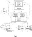
- the aircraft 101 comprises a ground manoeuvre control system 120 as described in relation to Figure 3 .
- a dashed line 102 indicates the lateral direction in relation to the aircraft. Any reference to “lateral movement” in relation to the illustrated embodiments refers to the component of movement of the aircraft in the direction of line 102.
- Dashed line 103 indicates the longitudinal axis of the aircraft. Any reference to “longitudinal movement” in relation to the illustrated embodiments refers to the component of movement of the aircraft along axis 103.
- the aircraft 101 is a commercial passenger jet.
- the aircraft 101 includes two sets of main landing gear (“MLG”), which are not steerable, each being in the form of two wheels on a common axle (four MLG wheels in total for the aircraft).
- MLG main landing gear
- the aircraft 101 also includes two nose wheels 112 on a common axle, which forms part of the nose landing gear (“NLG”) and associated nose-wheel steering mechanism.
- the aircraft 101 also includes engines 106a and 106b, a rudder 108 and spoilers 111a and 111b.
- the engines 106a and 106b, the spoilers 111a and 111b, and the wheel brakes 110a and 110b can be used by flight crew (e.g. a pilot) to control the longitudinal movement of the aircraft along a runway during ground manoeuvres.
- the rudder 108, the nose wheel 112 steering and the wheel brakes 110a and 110b can be used by the pilot to control the lateral movement of the aircraft along the runway during ground manoeuvres.
- lateral control under the pilot's direction may be best provided by the rudder pedals, whereas at lower groundspeeds, steering using the nose wheel only may be preferred by the pilot.
- wheel braking is the dominant mechanism for decelerating the aircraft.
- the aircraft of the embodiment shown in Figures 1 and 2 includes an aircraft ground manoeuvre control system 120 which is also shown in Figure 3 .
- the control system 120 comprises a "single pilot operations" unit (or SPO unit) 130, for use when the aircraft is being operated in a single pilot operation mode (which may be the only mode the aircraft is ever used in, or may be one of several modes, including for example a crewless mode and a multi-pilot mode).
- SPO unit 130 in this embodiment has the single function of assisting a pilot in the event of total failure of wheel brakes on one side of the aircraft.
- a total failure of wheel brakes on one side of the aircraft happens when the aircraft wheel brakes on either of the port-side MLG wheels or the star-board side are unable to respond to a command for braking, so that no braking is available on that side of the aircraft, whereas the wheel brakes for the other side are still able to respond.
- a failure may happen for example if there is a hydraulic fluid pipe rupture at a critical point.
- Another failure case may occur when all tyres on one side of the aircraft burst. Other failure cases may also exist.
- the SPO unit 130 responds to a detected total failure of wheel brakes on one side of the aircraft by commanding a NLG steering demand that counteracts, at least in part, the yaw moment induced on the aircraft when braking is applied to the faulty brake system(s) of the aircraft.
- the braking applied causes uncommanded differential braking, and a consequential yaw moment on the aircraft which would, if no other action is taken, cause the aircraft to steer away from its intended heading.
- the SPO unit 130 is a computer system (including a part of a computer system) suitably programmed with software 132, which interacts with the steering control functional block 134 and the braking control functional block 136 of the aircraft's braking and steering computer system 138.
- the steering control block 134 and the braking control block 136 will perform their normal functions of controlling steering of the NLG wheel and braking of the MLG wheels wholly independently of each other.
- the steering control block 134 outputs signals to the NLG steering actuators of the NLG steering system 140, and receives signals from the NLG steering system 140, for example confirming the angular (steering) position of the NLG wheel 112.
- the braking control block 136 outputs signals to the actuators of the brakes 142 for the MLG wheels 104, and receives signals regarding the wheels and/or brakes 142, for example confirming the amount of braking applied, tyre pressures and wheel speed.
- the braking and steering computer system 138 thus controls the MLG brakes and NLG steering in response to various inputs 139 which may for example include a pilot-originating command to steer the NLG and/or to apply the brakes to the MLG wheels.
- the SPO unit 130 receives data (or a signal, or other indication) from the braking and steering computer 138 that the wheels on one side of the aircraft have failed, resulting in no braking being available.
- data or a signal, or other indication
- Such a failure may for example be detected as a result of the braking and steering computer system 138 performing functional monitoring by processing the tyre pressure / wheel speed data received, and possibly other data, to determine whether a fault or failure has occurred.
- the system takes an appropriate sanction inside the computer and also outputs information to other systems, for example flight warning, to provide an appropriate indication to the flight crew.
- the SPO unit 130 responds as follows.
- a command for wheel braking is received by the braking and steering computer system 138.
- the braking control block 136 outputs a braking command to the MLG brakes 142.
- the commanded level of braking is reported by the braking control block 136 to the SPO unit 130.
- the SPO unit 130 causes the steering control block 134 to issue a command to the NLG to rotate to compensate for the asymmetric braking that is caused by the combination of the braking applied to the MLG brakes 142 and the fault/failure on one side only.
- the asymmetric braking caused by applying brakes only on the starboard side will of itself cause the aircraft to turn towards the starboard side, with the aircraft undergoing rotational movement about a vertical axis in a clockwise direction when viewed from above (otherwise known as yawing).
- This may be considered as being a case of uncommanded differential braking.
- a flight crew may apply different levels of braking on the MLG wheels on one side of the aircraft in comparison to the MLG wheels on the other side of the aircraft, so as to apply differential braking on purpose, so as to assist in turning or steering the aircraft.
- To counteract the fault-induced i.e.
- the NLG wheel is rotated anticlockwise towards the port-side.
- the SPO unit on detecting the failure of the brakes automatically steers the NLG to compensate for the consequential asymmetrical braking of the MLG wheels.
- the effectiveness and safety of NLG steering is dependent on aircraft groundspeed.
- the amount of rotation of the NLG steering needed to compensate for asymmetric braking is determined by the SPO unit 130 in dependence on both the aircraft speed and the amount of braking commanded.
- the angular deflection from neutral is represented in Figure 1 , as the angle labelled 105 (in the drawing this being a negative number of degrees from the 0 degrees heading of straight ahead).
- At high runway speeds e.g.
- the maximum angular deflection is reduced to 1 degree.
- the angle of steering commanded also depends on the level of braking commanded. If full braking is commanded then the maximum amount of steering of the NLG permitted at the aircraft's speed is commanded. At a reduced level of braking commanded, the steering is reduced.
- the NLG wheel may be automatically steered to 0.5 degrees to compensate for asymmetric braking. If 20% braking is commanded, the NLG wheel may be automatically steered to 1 degree to compensate for asymmetric braking. If 50% braking is commanded, the NLG wheel may be automatically steered to 2.5 degrees, but only if the speed of the aircraft is low enough to permit that.
- the amount of automatic steering may be such that within a range of braking from a certain threshold to maximum braking, the angle of steering will always be the maximum permitted. In certain scenarios, the steering commanded by the SPO unit 130 will not be sufficient to counteract completely the turning motion of the aircraft caused by asymmetric braking, but will instead compensate for it in part.
- the graphs shown in Figure 4 and 5 show schematically a possible relationship between the NLG angle commanded by the SPO unit 130 in response to the braking demand, when the aircraft speed is 40 knots ( Figure 4 ) and when the aircraft speed is 100 knots or higher ( Figure 4 ).
- aircraft ground manoeuvre control system 120 including the SPO unit 130 in particular, is configured to assist in an automated response to brake failures when an aircraft is moving at speed on a runway and/or in taxiing manoeuvres. This can facilitate operations with reduced flight crew (e.g. fewer pilots, single pilot operations, and possibly pilotless operations) and/or function as an enhanced safety feature, for example in the event of incapacity of the pilot(s).
- the SPO unit 130 may be provided as software on one or more computer systems already present on a legacy aircraft.
- a legacy aircraft may include a braking and steering computer system having a steering control block and a braking control block already.
- the SPO unit may introduce very little extra complication when being integrated on an aircraft, whether that aircraft is a pre-existing aircraft, e.g. already having been in-service, being retrofitted with an SPO unit 130, whether that aircraft is to be manufactured according to designs modified from those of a legacy aircraft, or otherwise.
- the present embodiment is able to use existing signals that are used to generate the alerts on an aircraft of the prior art (e.g. brake-fault detected) and/or those signals / data that would normally provide information to the flight crew, such as aircraft heading, groundspeed and the like.
- FIG. 5 shows a flow diagram 200 showing an example method of controlling NLG steering of an aircraft moving on a runway according to a second embodiment.
- the method includes a step (box 201) of detecting failure of all wheel brakes on a first side of the aircraft, being the port-side or the starboard-side, the wheel brakes on the opposite side (a second side) still being at least partly operational. Then (or, in other cases, possibly before this step 201) there is a step (box 203) in which a pilot issues a wheel braking command causing a braking force to be applied to the MLG wheels of the aircraft.
- step 205 braking is applied only to the MLG wheels on the second side, which results in an asymmetry of braking force being applied to the wheels of the aircraft (step represented by box 205).
- the asymmetry of braking creates a moment force (about a vertical axis) which urges the aircraft to turn towards the second side.
- This asymmetry of braking is however compensated for by automatically performing the step represented by box 207.
- This compensating step 207 is performed immediately after the braking command is issued or possibly substantially at the same time.
- step 207 asymmetry of braking is compensated for by steering the NLG wheel towards the first side.
- the automated steering of the NLG wheels may compensate fully or in part for the asymmetry of braking force.
- the automated compensating of the asymmetry of braking force is limited to changing the steering angle of the NLG wheel.
- rudder control is not modified, as part of the method.
- An advantage of the embodiments described above is that, as a result of its lack of complication and its use of existing systems and data on the aircraft, it may easily retrofitted onto an existing aircraft.
- Figure 6 illustrates a method 300 of retrofitting an embodiment of the invention onto an existing aircraft so as to convert the aircraft into one in accordance with a further third embodiment of the present invention.
- the pre-existing systems on the aircraft already include a braking and steering computer system 338 having various computer-implemented modules including an independent steering control block 334 and an independent braking control block 336, substantially the same as described above in relation to the first embodiment.
- the method includes installing (the step illustrated by arrow 350) software onto the braking and steering computer system so as to cause the braking and steering computer system 338 to include the functionality of the SPO unit of the first embodiment and also to perform the method of the second embodiment.
- Both the steering control block 334 and the braking control block 336 receive inputs and send outputs, as described above.
- the software 332 once installed causes a new interaction between the steering control block 334 and the braking control block 336 such that the steering control block 334 causes the NLG to steer to compensate for faulty braking on one side of the aircraft notified to and/or by the braking control block 336.
- the SPO unit of the first embodiment could alternatively be embedded in software as an integrated element of the braking and steering computer.
- the SPO unit may form a part of a larger single pilot operations computer system that enables other functionality appropriate or of benefit for single pilot operations of the aircraft.
- the SPO unit could be embedded in software as an integrated element of a flight control computer of the aircraft, with appropriate data exchange with the braking and steering computer.
- Embodiments of the invention may also be used to compensate for a failure of the MLG brakes on one side of the aircraft in the form of constant braking being applied without the brakes being able to be released.
- the SPO unit is described above as being for use in supporting single pilot operations. Other embodiments are envisaged for use during normal operations, for example to limit the severity of an event associated with a loss of braking on a single gear, given that an automated system may be able to react faster and more appropriately than flight crew.
- the benefit of the embodiments may also have application on a taxiway in addition to on a runway.
Landscapes
- Engineering & Computer Science (AREA)
- Mechanical Engineering (AREA)
- Transportation (AREA)
- Aviation & Aerospace Engineering (AREA)
- Regulating Braking Force (AREA)
Applications Claiming Priority (1)
| Application Number | Priority Date | Filing Date | Title |
|---|---|---|---|
| GB2300829.5A GB2626530A (en) | 2023-01-19 | 2023-01-19 | System for controlling aircraft ground manoeuvres |
Publications (1)
| Publication Number | Publication Date |
|---|---|
| EP4403466A1 true EP4403466A1 (fr) | 2024-07-24 |
Family
ID=85383207
Family Applications (1)
| Application Number | Title | Priority Date | Filing Date |
|---|---|---|---|
| EP24151250.8A Withdrawn EP4403466A1 (fr) | 2023-01-19 | 2024-01-10 | Système de commande de manoeuvre au sol d'un aéronef |
Country Status (3)
| Country | Link |
|---|---|
| US (1) | US20240246663A1 (fr) |
| EP (1) | EP4403466A1 (fr) |
| GB (1) | GB2626530A (fr) |
Citations (9)
| Publication number | Priority date | Publication date | Assignee | Title |
|---|---|---|---|---|
| US6923510B2 (en) * | 2003-09-17 | 2005-08-02 | Delphi Technologies, Inc. | Control of brake-and steer-by-wire systems during brake failure |
| US8108086B2 (en) | 2007-06-11 | 2012-01-31 | Airbus Operations Sas | System for guiding and piloting an aircraft in case of inability of the pilots |
| WO2012145608A1 (fr) | 2011-04-20 | 2012-10-26 | Vos David W | Systèmes et procédés pour l'atterrissage autonome d'un avion |
| US8521365B2 (en) | 2008-03-18 | 2013-08-27 | Airbus Operations (Sas) | Method and device for the lateral control of a taxiing aircraft |
| GB2540182A (en) * | 2015-07-08 | 2017-01-11 | Airbus Operations Ltd | Aircraft steering system controller |
| US10081346B2 (en) | 2015-07-08 | 2018-09-25 | Airbus Operations Limited | Braking control system for an aircraft |
| WO2021127352A1 (fr) * | 2019-12-20 | 2021-06-24 | Meggitt Aircraft Braking Systems Corporation | Système de réduction de lacet et procédé de freinage d'aéronef |
| US20210287560A1 (en) | 2020-03-10 | 2021-09-16 | Honeywell International Inc. | Systems and methods providing assist-to-land and emergency land functions |
| US20220058970A1 (en) | 2016-02-29 | 2022-02-24 | Garmin International, Inc. | Emergency autoland system |
Family Cites Families (7)
| Publication number | Priority date | Publication date | Assignee | Title |
|---|---|---|---|---|
| US20160154642A1 (en) * | 2012-08-14 | 2016-06-02 | The Boeing Company | Aircraft Software Configuration Selection and Installation |
| JP7185498B2 (ja) * | 2018-11-12 | 2022-12-07 | 株式会社Subaru | 回転翼航空機及び回転翼航空機の制御方法 |
| US11263912B2 (en) * | 2019-08-15 | 2022-03-01 | Gulfstream Aerospace Corporation | Aircraft taxi assistance avionics |
| RU2727225C1 (ru) * | 2019-10-30 | 2020-07-21 | Акционерное общество "Лётно-исследовательский институт имени М.М. Громова" | Способ и система предотвращения бокового увода летательного аппарата с взлётно-посадочной полосы |
| CN111544797A (zh) * | 2020-04-02 | 2020-08-18 | 峰飞国际有限公司 | 一种应用于无人机的高空抛投瞄准方法及系统、存储介质 |
| GB2596290C (en) * | 2020-06-22 | 2023-09-20 | L Univ Ta Malta | A method |
| US12122347B2 (en) * | 2022-08-29 | 2024-10-22 | Goodrich Corporation | System and method to address uncommanded brake (UCB) application and brake temperature sensing using primary and alternate architecture |
-
2023
- 2023-01-19 GB GB2300829.5A patent/GB2626530A/en active Pending
-
2024
- 2024-01-10 EP EP24151250.8A patent/EP4403466A1/fr not_active Withdrawn
- 2024-01-17 US US18/415,079 patent/US20240246663A1/en active Pending
Patent Citations (9)
| Publication number | Priority date | Publication date | Assignee | Title |
|---|---|---|---|---|
| US6923510B2 (en) * | 2003-09-17 | 2005-08-02 | Delphi Technologies, Inc. | Control of brake-and steer-by-wire systems during brake failure |
| US8108086B2 (en) | 2007-06-11 | 2012-01-31 | Airbus Operations Sas | System for guiding and piloting an aircraft in case of inability of the pilots |
| US8521365B2 (en) | 2008-03-18 | 2013-08-27 | Airbus Operations (Sas) | Method and device for the lateral control of a taxiing aircraft |
| WO2012145608A1 (fr) | 2011-04-20 | 2012-10-26 | Vos David W | Systèmes et procédés pour l'atterrissage autonome d'un avion |
| GB2540182A (en) * | 2015-07-08 | 2017-01-11 | Airbus Operations Ltd | Aircraft steering system controller |
| US10081346B2 (en) | 2015-07-08 | 2018-09-25 | Airbus Operations Limited | Braking control system for an aircraft |
| US20220058970A1 (en) | 2016-02-29 | 2022-02-24 | Garmin International, Inc. | Emergency autoland system |
| WO2021127352A1 (fr) * | 2019-12-20 | 2021-06-24 | Meggitt Aircraft Braking Systems Corporation | Système de réduction de lacet et procédé de freinage d'aéronef |
| US20210287560A1 (en) | 2020-03-10 | 2021-09-16 | Honeywell International Inc. | Systems and methods providing assist-to-land and emergency land functions |
Also Published As
| Publication number | Publication date |
|---|---|
| GB2626530A (en) | 2024-07-31 |
| US20240246663A1 (en) | 2024-07-25 |
| GB202300829D0 (en) | 2023-03-08 |
Similar Documents
| Publication | Publication Date | Title |
|---|---|---|
| CN106335632B (zh) | 用于飞行器的制动控制系统 | |
| CN106335633B (zh) | 用于飞行器起落架性能监测的数据处理单元 | |
| CN102016738B (zh) | 用于横向操纵在地面上滑行的飞行器的方法和装置 | |
| EP2920070B1 (fr) | Dstributeur de forces et de couple de braquage pour système de propulsion ou de freinage d'un atterrisseur d'aéronef | |
| EP2540621B1 (fr) | Système de commande pour aéronef, procédé de commande d'aéronef et aéronef | |
| EP4001104B1 (fr) | Commande de force longitudinale de train d'atterrissage d'aéronef | |
| CN106335634B (zh) | 飞行器及其转向系统、转向方法和转向系统控制器 | |
| US10065729B2 (en) | Control method and apparatus for an aircraft when taxiing | |
| US20160046364A1 (en) | Systems for inceptor control in fly-by-wire aircraft systems | |
| US9272770B2 (en) | Method and apparatus for improved lateral control of an aircraft on the ground during takeoff | |
| CN106828884A (zh) | 水陆两栖飞机飞控系统加装控制增稳系统的方法 | |
| EP3141976B1 (fr) | Limiteur de vitesse angulaire de roulis dépendant de l'assiette latérale | |
| EP4403466A1 (fr) | Système de commande de manoeuvre au sol d'un aéronef | |
| EP4325316B1 (fr) | Procédé et appareil de commande de manoeuvres au sol d'un aéronef | |
| EP3232284A1 (fr) | Procédé et appareil pour la commande d'un train d'atterrissage orientable | |
| EP4063266A1 (fr) | Système de surveillance pour aéronef | |
| EP4042250B1 (fr) | Système de commande de cap | |
| CN120681329A (zh) | 飞机地面转向系统及飞机地面转向控制方法 |
Legal Events
| Date | Code | Title | Description |
|---|---|---|---|
| PUAI | Public reference made under article 153(3) epc to a published international application that has entered the european phase |
Free format text: ORIGINAL CODE: 0009012 |
|
| STAA | Information on the status of an ep patent application or granted ep patent |
Free format text: STATUS: THE APPLICATION HAS BEEN PUBLISHED |
|
| AK | Designated contracting states |
Kind code of ref document: A1 Designated state(s): AL AT BE BG CH CY CZ DE DK EE ES FI FR GB GR HR HU IE IS IT LI LT LU LV MC ME MK MT NL NO PL PT RO RS SE SI SK SM TR |
|
| STAA | Information on the status of an ep patent application or granted ep patent |
Free format text: STATUS: THE APPLICATION IS DEEMED TO BE WITHDRAWN |
|
| 18D | Application deemed to be withdrawn |
Effective date: 20250125 |