EP4403865A1 - Echangeur de chaleur - Google Patents
Echangeur de chaleur Download PDFInfo
- Publication number
- EP4403865A1 EP4403865A1 EP24151996.6A EP24151996A EP4403865A1 EP 4403865 A1 EP4403865 A1 EP 4403865A1 EP 24151996 A EP24151996 A EP 24151996A EP 4403865 A1 EP4403865 A1 EP 4403865A1
- Authority
- EP
- European Patent Office
- Prior art keywords
- heat exchanger
- sheet portion
- fins
- length
- sheet
- Prior art date
- Legal status (The legal status is an assumption and is not a legal conclusion. Google has not performed a legal analysis and makes no representation as to the accuracy of the status listed.)
- Granted
Links
Images




Classifications
-
- F—MECHANICAL ENGINEERING; LIGHTING; HEATING; WEAPONS; BLASTING
- F28—HEAT EXCHANGE IN GENERAL
- F28F—DETAILS OF HEAT-EXCHANGE AND HEAT-TRANSFER APPARATUS, OF GENERAL APPLICATION
- F28F1/00—Tubular elements; Assemblies of tubular elements
- F28F1/10—Tubular elements and assemblies thereof with means for increasing heat-transfer area, e.g. with fins, with projections, with recesses
- F28F1/12—Tubular elements and assemblies thereof with means for increasing heat-transfer area, e.g. with fins, with projections, with recesses the means being only outside the tubular element
- F28F1/24—Tubular elements and assemblies thereof with means for increasing heat-transfer area, e.g. with fins, with projections, with recesses the means being only outside the tubular element and extending transversely
- F28F1/32—Tubular elements and assemblies thereof with means for increasing heat-transfer area, e.g. with fins, with projections, with recesses the means being only outside the tubular element and extending transversely the means having portions engaging further tubular elements
- F28F1/325—Fins with openings
-
- F—MECHANICAL ENGINEERING; LIGHTING; HEATING; WEAPONS; BLASTING
- F28—HEAT EXCHANGE IN GENERAL
- F28F—DETAILS OF HEAT-EXCHANGE AND HEAT-TRANSFER APPARATUS, OF GENERAL APPLICATION
- F28F1/00—Tubular elements; Assemblies of tubular elements
- F28F1/10—Tubular elements and assemblies thereof with means for increasing heat-transfer area, e.g. with fins, with projections, with recesses
- F28F1/12—Tubular elements and assemblies thereof with means for increasing heat-transfer area, e.g. with fins, with projections, with recesses the means being only outside the tubular element
- F28F1/24—Tubular elements and assemblies thereof with means for increasing heat-transfer area, e.g. with fins, with projections, with recesses the means being only outside the tubular element and extending transversely
- F28F1/32—Tubular elements and assemblies thereof with means for increasing heat-transfer area, e.g. with fins, with projections, with recesses the means being only outside the tubular element and extending transversely the means having portions engaging further tubular elements
-
- F—MECHANICAL ENGINEERING; LIGHTING; HEATING; WEAPONS; BLASTING
- F28—HEAT EXCHANGE IN GENERAL
- F28F—DETAILS OF HEAT-EXCHANGE AND HEAT-TRANSFER APPARATUS, OF GENERAL APPLICATION
- F28F17/00—Removing ice or water from heat-exchange apparatus
- F28F17/005—Means for draining condensates from heat exchangers, e.g. from evaporators
-
- F—MECHANICAL ENGINEERING; LIGHTING; HEATING; WEAPONS; BLASTING
- F24—HEATING; RANGES; VENTILATING
- F24F—AIR-CONDITIONING; AIR-HUMIDIFICATION; VENTILATION; USE OF AIR CURRENTS FOR SCREENING
- F24F1/00—Room units for air-conditioning, e.g. separate or self-contained units or units receiving primary air from a central station
- F24F1/0007—Indoor units, e.g. fan coil units
- F24F1/0059—Indoor units, e.g. fan coil units characterised by heat exchangers
-
- F—MECHANICAL ENGINEERING; LIGHTING; HEATING; WEAPONS; BLASTING
- F24—HEATING; RANGES; VENTILATING
- F24F—AIR-CONDITIONING; AIR-HUMIDIFICATION; VENTILATION; USE OF AIR CURRENTS FOR SCREENING
- F24F1/00—Room units for air-conditioning, e.g. separate or self-contained units or units receiving primary air from a central station
- F24F1/0007—Indoor units, e.g. fan coil units
- F24F1/0059—Indoor units, e.g. fan coil units characterised by heat exchangers
- F24F1/0067—Indoor units, e.g. fan coil units characterised by heat exchangers by the shape of the heat exchangers or of parts thereof, e.g. of their fins
-
- F—MECHANICAL ENGINEERING; LIGHTING; HEATING; WEAPONS; BLASTING
- F24—HEATING; RANGES; VENTILATING
- F24F—AIR-CONDITIONING; AIR-HUMIDIFICATION; VENTILATION; USE OF AIR CURRENTS FOR SCREENING
- F24F1/00—Room units for air-conditioning, e.g. separate or self-contained units or units receiving primary air from a central station
- F24F1/06—Separate outdoor units, e.g. outdoor unit to be linked to a separate room comprising a compressor and a heat exchanger
- F24F1/14—Heat exchangers specially adapted for separate outdoor units
- F24F1/18—Heat exchangers specially adapted for separate outdoor units characterised by their shape
-
- F—MECHANICAL ENGINEERING; LIGHTING; HEATING; WEAPONS; BLASTING
- F25—REFRIGERATION OR COOLING; COMBINED HEATING AND REFRIGERATION SYSTEMS; HEAT PUMP SYSTEMS; MANUFACTURE OR STORAGE OF ICE; LIQUEFACTION SOLIDIFICATION OF GASES
- F25B—REFRIGERATION MACHINES, PLANTS OR SYSTEMS; COMBINED HEATING AND REFRIGERATION SYSTEMS; HEAT PUMP SYSTEMS
- F25B39/00—Evaporators; Condensers
-
- F—MECHANICAL ENGINEERING; LIGHTING; HEATING; WEAPONS; BLASTING
- F28—HEAT EXCHANGE IN GENERAL
- F28D—HEAT-EXCHANGE APPARATUS, NOT PROVIDED FOR IN ANOTHER SUBCLASS, IN WHICH THE HEAT-EXCHANGE MEDIA DO NOT COME INTO DIRECT CONTACT
- F28D1/00—Heat-exchange apparatus having stationary conduit assemblies for one heat-exchange medium only, the media being in contact with different sides of the conduit wall, in which the other heat-exchange medium is a large body of fluid, e.g. domestic or motor car radiators
- F28D1/02—Heat-exchange apparatus having stationary conduit assemblies for one heat-exchange medium only, the media being in contact with different sides of the conduit wall, in which the other heat-exchange medium is a large body of fluid, e.g. domestic or motor car radiators with heat-exchange conduits immersed in the body of fluid
- F28D1/04—Heat-exchange apparatus having stationary conduit assemblies for one heat-exchange medium only, the media being in contact with different sides of the conduit wall, in which the other heat-exchange medium is a large body of fluid, e.g. domestic or motor car radiators with heat-exchange conduits immersed in the body of fluid with tubular conduits
- F28D1/047—Heat-exchange apparatus having stationary conduit assemblies for one heat-exchange medium only, the media being in contact with different sides of the conduit wall, in which the other heat-exchange medium is a large body of fluid, e.g. domestic or motor car radiators with heat-exchange conduits immersed in the body of fluid with tubular conduits the conduits being bent, e.g. in a serpentine or zig-zag
- F28D1/0477—Heat-exchange apparatus having stationary conduit assemblies for one heat-exchange medium only, the media being in contact with different sides of the conduit wall, in which the other heat-exchange medium is a large body of fluid, e.g. domestic or motor car radiators with heat-exchange conduits immersed in the body of fluid with tubular conduits the conduits being bent, e.g. in a serpentine or zig-zag the conduits being bent in a serpentine or zig-zag
-
- F—MECHANICAL ENGINEERING; LIGHTING; HEATING; WEAPONS; BLASTING
- F28—HEAT EXCHANGE IN GENERAL
- F28D—HEAT-EXCHANGE APPARATUS, NOT PROVIDED FOR IN ANOTHER SUBCLASS, IN WHICH THE HEAT-EXCHANGE MEDIA DO NOT COME INTO DIRECT CONTACT
- F28D1/00—Heat-exchange apparatus having stationary conduit assemblies for one heat-exchange medium only, the media being in contact with different sides of the conduit wall, in which the other heat-exchange medium is a large body of fluid, e.g. domestic or motor car radiators
- F28D1/02—Heat-exchange apparatus having stationary conduit assemblies for one heat-exchange medium only, the media being in contact with different sides of the conduit wall, in which the other heat-exchange medium is a large body of fluid, e.g. domestic or motor car radiators with heat-exchange conduits immersed in the body of fluid
- F28D1/04—Heat-exchange apparatus having stationary conduit assemblies for one heat-exchange medium only, the media being in contact with different sides of the conduit wall, in which the other heat-exchange medium is a large body of fluid, e.g. domestic or motor car radiators with heat-exchange conduits immersed in the body of fluid with tubular conduits
- F28D1/053—Heat-exchange apparatus having stationary conduit assemblies for one heat-exchange medium only, the media being in contact with different sides of the conduit wall, in which the other heat-exchange medium is a large body of fluid, e.g. domestic or motor car radiators with heat-exchange conduits immersed in the body of fluid with tubular conduits the conduits being straight
-
- F—MECHANICAL ENGINEERING; LIGHTING; HEATING; WEAPONS; BLASTING
- F28—HEAT EXCHANGE IN GENERAL
- F28F—DETAILS OF HEAT-EXCHANGE AND HEAT-TRANSFER APPARATUS, OF GENERAL APPLICATION
- F28F1/00—Tubular elements; Assemblies of tubular elements
- F28F1/10—Tubular elements and assemblies thereof with means for increasing heat-transfer area, e.g. with fins, with projections, with recesses
- F28F1/12—Tubular elements and assemblies thereof with means for increasing heat-transfer area, e.g. with fins, with projections, with recesses the means being only outside the tubular element
- F28F1/126—Tubular elements and assemblies thereof with means for increasing heat-transfer area, e.g. with fins, with projections, with recesses the means being only outside the tubular element consisting of zig-zag shaped fins
-
- F—MECHANICAL ENGINEERING; LIGHTING; HEATING; WEAPONS; BLASTING
- F28—HEAT EXCHANGE IN GENERAL
- F28F—DETAILS OF HEAT-EXCHANGE AND HEAT-TRANSFER APPARATUS, OF GENERAL APPLICATION
- F28F1/00—Tubular elements; Assemblies of tubular elements
- F28F1/10—Tubular elements and assemblies thereof with means for increasing heat-transfer area, e.g. with fins, with projections, with recesses
- F28F1/12—Tubular elements and assemblies thereof with means for increasing heat-transfer area, e.g. with fins, with projections, with recesses the means being only outside the tubular element
- F28F1/126—Tubular elements and assemblies thereof with means for increasing heat-transfer area, e.g. with fins, with projections, with recesses the means being only outside the tubular element consisting of zig-zag shaped fins
- F28F1/128—Fins with openings, e.g. louvered fins
-
- F—MECHANICAL ENGINEERING; LIGHTING; HEATING; WEAPONS; BLASTING
- F28—HEAT EXCHANGE IN GENERAL
- F28D—HEAT-EXCHANGE APPARATUS, NOT PROVIDED FOR IN ANOTHER SUBCLASS, IN WHICH THE HEAT-EXCHANGE MEDIA DO NOT COME INTO DIRECT CONTACT
- F28D1/00—Heat-exchange apparatus having stationary conduit assemblies for one heat-exchange medium only, the media being in contact with different sides of the conduit wall, in which the other heat-exchange medium is a large body of fluid, e.g. domestic or motor car radiators
- F28D1/02—Heat-exchange apparatus having stationary conduit assemblies for one heat-exchange medium only, the media being in contact with different sides of the conduit wall, in which the other heat-exchange medium is a large body of fluid, e.g. domestic or motor car radiators with heat-exchange conduits immersed in the body of fluid
- F28D1/04—Heat-exchange apparatus having stationary conduit assemblies for one heat-exchange medium only, the media being in contact with different sides of the conduit wall, in which the other heat-exchange medium is a large body of fluid, e.g. domestic or motor car radiators with heat-exchange conduits immersed in the body of fluid with tubular conduits
-
- F—MECHANICAL ENGINEERING; LIGHTING; HEATING; WEAPONS; BLASTING
- F28—HEAT EXCHANGE IN GENERAL
- F28D—HEAT-EXCHANGE APPARATUS, NOT PROVIDED FOR IN ANOTHER SUBCLASS, IN WHICH THE HEAT-EXCHANGE MEDIA DO NOT COME INTO DIRECT CONTACT
- F28D21/00—Heat-exchange apparatus not covered by any of the groups F28D1/00 - F28D20/00
- F28D2021/0019—Other heat exchangers for particular applications; Heat exchange systems not otherwise provided for
- F28D2021/0068—Other heat exchangers for particular applications; Heat exchange systems not otherwise provided for for refrigerant cycles
-
- F—MECHANICAL ENGINEERING; LIGHTING; HEATING; WEAPONS; BLASTING
- F28—HEAT EXCHANGE IN GENERAL
- F28D—HEAT-EXCHANGE APPARATUS, NOT PROVIDED FOR IN ANOTHER SUBCLASS, IN WHICH THE HEAT-EXCHANGE MEDIA DO NOT COME INTO DIRECT CONTACT
- F28D21/00—Heat-exchange apparatus not covered by any of the groups F28D1/00 - F28D20/00
- F28D2021/0019—Other heat exchangers for particular applications; Heat exchange systems not otherwise provided for
- F28D2021/0068—Other heat exchangers for particular applications; Heat exchange systems not otherwise provided for for refrigerant cycles
- F28D2021/007—Condensers
-
- F—MECHANICAL ENGINEERING; LIGHTING; HEATING; WEAPONS; BLASTING
- F28—HEAT EXCHANGE IN GENERAL
- F28D—HEAT-EXCHANGE APPARATUS, NOT PROVIDED FOR IN ANOTHER SUBCLASS, IN WHICH THE HEAT-EXCHANGE MEDIA DO NOT COME INTO DIRECT CONTACT
- F28D21/00—Heat-exchange apparatus not covered by any of the groups F28D1/00 - F28D20/00
- F28D2021/0019—Other heat exchangers for particular applications; Heat exchange systems not otherwise provided for
- F28D2021/0068—Other heat exchangers for particular applications; Heat exchange systems not otherwise provided for for refrigerant cycles
- F28D2021/0071—Evaporators
-
- F—MECHANICAL ENGINEERING; LIGHTING; HEATING; WEAPONS; BLASTING
- F28—HEAT EXCHANGE IN GENERAL
- F28F—DETAILS OF HEAT-EXCHANGE AND HEAT-TRANSFER APPARATUS, OF GENERAL APPLICATION
- F28F2215/00—Fins
Definitions
- a heat exchanger can be used as a condenser or an evaporator in a refrigeration cycle device including a compressor, a condenser, an expansion mechanism, and an evaporator.
- a heat exchanger can be installed in a vehicle, a refrigerator, and the like to exchange heat between refrigerant and air.
- a plate fin for improving the heat transfer rate on the fin side without an increase in pressure loss on the air side is disclosed in Related Art 1, which is hereby incorporated by reference.
- the plate fin has a plurality of crest portions formed along a column direction, and the shape of a sheet portion around a through-hole is formed in an oval shape elongated horizontally.
- a heat exchanger includes: a heat transfer pipe to guide a refrigerant; and a plurality of fins spaced apart from each other to allow air to pass in a first direction, the plurality of fins each having a through-hole through which the heat transfer pipe is installed, wherein the plurality of fins each includes: a corrugated portion formed in a zigzag shape proceeding in the first direction, which is an air flow direction; and a sheet portion recessed from the corrugated portion around the through-hole to be parallel with the first direction, and, when dividing a fin, among the plurality of fins, into a plurality of units with respect to one sheet portion, an area of the sheet portion corresponds to 16% or more of an area of one unit.
- the sheet portion may have a first length in the first direction, which is an air flow direction, and a second length in a second direction perpendicular to the air flow direction, the second length being greater than the first length.
- the plurality of fins may each further include a collar in surface contact with the heat transfer pipe.
- the sheet portion may be connected to an outer surface of the collar.
- the corrugated portion may be disposed between adjacent sheet portions.
- the corrugated portion may include four inclined portions, two crest portions, and one trough portion, with respect to one sheet portion.
- the sheet portion may be formed in two inner inclined portions that are disposed between the two crest portions and define the through portion therebetween.
- An overlapping length between the inner inclined portion and the crest portion may be greater than or equal to 50% of the second length of the sheet portion in the second direction.
- a ratio of the second length of the sheet portion to the first length of the sheet portion may be in a range of 1.2 to 1.9.
- the two crest portions may be disposed so as not to overlap the sheet portion in the second direction.
- the two crest portions may be positioned higher than the sheet portion in a third direction perpendicular to the first direction and the second direction.
- the plurality of fins may each further include a connecting portion to connect the corrugated portion and the sheet portion.
- the sheet portion may be configured such that a distance to the through-hole in the second direction is greater than a distance to the through-hole in the first direction.
- an air conditioner includes: an indoor heat exchanger configured to exchange heat with indoor air; and an outdoor heat exchanger configured to exchange heat with outdoor air, wherein at least one of the indoor heat exchanger and the outdoor heat exchanger includes: a heat transfer pipe to guide a refrigerant; and a plurality of fins spaced apart from each other to allow air to pass in a first direction, the plurality of fins each having a through-hole through which the heat transfer pipe vertically passes, wherein the plurality of fins each includes: a corrugated portion formed in a zigzag shape proceeding in the first direction, which is an air flow direction; and a sheet portion recessed from the corrugated portion around the through-hole to be parallel with the first direction, and wherein, when dividing a fin, among the plurality of fins, into a plurality of units with respect to one sheet portion, an area of the sheet portion corresponds to 16% or more with respect to an area of one unit, and a separation distance exists between the plurality of fins.
- a heat exchanger according to embodiments of the present disclosure has one or more of the following effects.
- a corrugated portion formed in a zigzag shape proceeding in a first direction, which is an air flow direction, and a sheet portion configured as a flat surface adjacent to the through-hole is provided, the mixing of air in a region adjacent to the corrugated portion and the through-hole can be facilitated.
- Spatially relative terms such as “below”, “beneath”, “lower”, “above”, “upper”, etc., can be used to easily describe the correlation between one component and another component as shown in the drawing.
- Spatially relative terms should be understood as including different directions of components at the time of use or operation in addition to the directions shown in the drawing. For example, when reversing a spherical element shown in the drawing, a component described as “below” or “beneath” of another component may be placed “above” another component. Thus, the illustrative term “below” may include both the lower and the above directions. Components can also be oriented in different directions, so that spatially relative terms can be interpreted according to the orientation.
- each component in the drawings has been exaggerated, omitted, or schematically shown for ease of description and clarity.
- the size and area of each component do not fully reflect the actual size or area.
- FIG. 1 is a schematic diagram of an air conditioner in heating operation, according to an embodiment of the present disclosure.
- an air conditioner 1 includes an outdoor unit 10 provided in an outdoor space, a plurality of indoor units 20 provided in an indoor space, and a refrigerant pipe 30 through which refrigerant circulates between the outdoor unit 10 and the plurality of indoor units 20.
- two indoor units 20 are connected to one outdoor unit 10.
- the indoor unit 20 includes an indoor heat exchanger 21 for heat exchange between indoor air and refrigerant, an indoor blower 22 to allow indoor air to pass through the indoor heat exchanger 21, and an indoor expansion valve 23 to depressurize and expand refrigerant.
- the refrigerant pipe 30 includes a liquid refrigerant pipe 31 through which liquid refrigerant passes, and a gas refrigerant pipe 32 through which gaseous refrigerant passes.
- the liquid refrigerant pipe 31 allows refrigerant to flow between the indoor expansion valve 23 and the outdoor expansion valve 13.
- the gas refrigerant pipe 32 guides refrigerant to flow between the four-way valve 14 of the outdoor unit 10 and the gas side of the indoor heat exchanger 21 of the indoor unit 20.
- any one of HC refrigerant, HC mixed refrigerant, R32, R410A, R407C, and carbon dioxide may be preferably used.
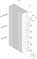
- FIG. 2 is a perspective view of a heat exchanger according to an embodiment of the present disclosure
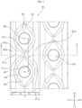
- FIG. 3 is an enlarged plan view showing a portion of a fin according to an embodiment of the disclosure.
- a plurality of heat transfer pipes 60 extend in a left-right direction (second direction) (LeRi) perpendicular to an air flow direction.
- the plurality of heat transfer pipes 60 may include a plurality of first-row heat transfer pipes 60a spaced apart from each other in an up-down direction (third direction) (UD), and a plurality of second-row heat transfer pipes 60b spaced rearward from the first-row heat transfer pipes 60a and spaced apart from each other in the up-down direction.
- a pitch between the first-row heat transfer pipes 60a is the same as a pitch between the second-row heat transfer pipes 60b, and the first-row heat transfer pipes 60a and the second-row heat transfer pipes 60b are arranged so as not to overlap each other in a front-rear direction (first direction) (FR).
- first direction first direction
- resistance exerted by the heat transfer pipes 60 on air flowing in the front-rear direction may be reduced.
- the collar 84 may be configured such that a height protruding in an upward direction of the sheet portion 85 and a height protruding in a downward direction of the sheet portion 85 are different, and the height protruding in the upward direction may be greater.
- heat exchange between refrigerant and air can be efficiently achieved in the sheet portion 85, allowing more air to come into contact with the sheet portion 85.
- heat exchange efficiency of the heat exchanger 40 can be improved.
- the number of corrugated fins 80 coupled per length of the heat transfer pipe 60 can be significantly lower, which corresponds to 1/2 to 1/3 of the general number.
- a separation distance of neighboring or adjacent corrugated fins 80 may be greater than the height of the collar 84.
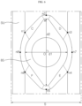
- FIG. 4 is an enlarged plan view showing one unit of the fin in FIG. 3
- FIG. 5 is a cross-sectional view taken along line I-I' of the fin in FIG. 3
- FIG. 6 is an enlarged view showing a portion of FIG. 3 .
- the sheet portion 85 may define a surface aligned with the first direction, around the through-hole 89.
- the sheet portion 85 may be defined as a surface aligned with the first direction (F-R direction) and the second direction (Ri-Le direction), around the through-hole 89.
- the sheet portion 85 may be defined to have an oval shape elongated vertically.
- the oval shape is only defined as having the second length d2 in the second direction greater than the first length d1 in the first direction, and all of its boundary surfaces are not necessarily having curvature.
- the shape of the sheet portion 85 is only defined as a shape elongated vertically, namely, a shape elongated in the second direction perpendicular to the air flow direction.
- the corrugated fin 80 includes a corrugated portion.
- the corrugated portion is a region formed in a zigzag shape proceeding in the first direction, which is the air flow direction.
- the corrugated portion is disposed between adjacent sheet portions 85.
- the corrugated portion includes four inclined portions 82a, 82b, 82c and 82d, two crest portions 81a and 81b, and one trough portion 81c.
- the two crest portions 81a and 81b and the one trough portion 81c are defined by the four inclined portions 82a, 82b, 82c, and 82d.
- the four inclined portions 82a, 82b, 82c, and 82d have an inclination with respect to the first direction (F-R direction), and extend in the second direction.
- the inclined portions may include a first inclined portion 82a that is connected to the front of the first crest portion 81a, a second inclined portion 82b that is connected to the rear of the first crest portion 81a and connects the first crest portion 81a and the trough portion 81c, a third inclined portion 82c that is connected to the front of the second crest portion 81b and connects the second crest portion 81b and the trough portion 81c, and a fourth inclined portion 82d that is connected to the rear of the second crest portion 81b.
- the crest portions 81a and 81b, and the trough portion 81c are folded portions when the corrugated fin 80 is bent to form the inclined portions 82a, 82b, 82c and 82d, and the inclined portions 82a, 82b, 82c, and 82d are inclined surfaces inclined with respect to the surface of the fin 80 before the formation of the inclined portions 82a, 82b, 82c, and 82d.
- the second inclined portion 82b may decrease in width in the second direction from front to rear, and the third inclined portion 82c may increase in width in the second direction from front to rear.
- an area of the sheet portion 85 having the first length d1 in the first direction, which is the same direction as the sum (P1 + P1) of the lengths of the second and third inclined portions 82b and 82c, may be secured, thereby improving the heat exchange efficiency.
- the first crest portion 81a, the second crest portion 81b, and the trough portion 81c extend in the second direction.
- a center O of the through-hole 89 may be located to overlap the trough portion 81c in the second direction.
- the two crest portions 81a and 81b may be disposed so as not to overlap the through-hole 89 in the second direction.
- the first inclination angle ⁇ 1 of the first inclined portion 82a with the first direction and the fourth inclination angle ⁇ 4 of the fourth inclined portion 82d with the first direction may be greater than the second inclination angle ⁇ 2 of the second inclined portion 82b with the first direction and the third inclination angle ⁇ 3 of the third inclined portion 82c with the first direction.
- the interval H between the heat transfer pipes 60 is defined as a distance from a center O of one heat transfer pipe 60 to a center O of another (or next) heat transfer pipe 60 in the second direction.
- the sheet portion 85 may have a curvature at each local extremum point of four directions which are farthest points from the center O of the heat transfer pipe 60, and a distance between the local extremum points of the four directions may be a straight line.
- a distance between each local extremum point and the through-hole 89 may be greater in the second direction than the first direction. That is, the area defining the sheet portion 85 is larger vertically.
- a ratio of the second length d2 of the sheet portion 85 to the first length d1 of the sheet portion 85 may preferably be in a range of 1.2 to 1.9.
- the corrugated fin 80 has a predetermined ratio between the area of the sheet portion 85, namely, an area A of the oval shape (which has the first length d1 and the second length d2) and an area B1, B2 of a corrugated portion on top thereof.
- a region of the corrugated portion includes triangular shapes in which portions of the second inclined portion 82b and the third inclined portion 82c are symmetrical with each other.
- the second inclined portion 82b defines a first triangle B1 and the third inclined portion 82c defines a second triangle B2, and the first triangle B1 and the second triangle B2 are arranged to be point symmetric with respect to a point passing through the trough portion 81c.
- the sum of areas of the first triangle B1 and the second triangle B2 may correspond to 60 to 80% of the area A of the sheet portion 85.
- the overlapping length h1 may correspond to 50% or more of the second length d2.
- the upward and downward movement of air may be facilitated even when the number of fins 80 is small, thereby achieving the heat exchange performance.
- the function to increase heat exchange may be sufficiently achieved using the predetermined ratio of the area and overlapping length of the corrugated portion to the area and length of the sheet portion 85.
- each of the partition surfaces C, D, E, and F is configured such that a distance from each of the horizontal and vertical contact points (n7, n8, n2, n5) to the sheet portion 85 is the shortest, and a distance from each of the inclined contact points (n1, n3, n4, n6) to the sheet portion 85 is the longest.
- the area S85 defining the sheet portion 85 may correspond to 16 to 25% of an entire area of one reference region SU.
- the flow rate of air flowing through the sheet portion 85 is increased, thereby facilitating heat exchange with the heat transfer pipe 60.
- FIG. 7 illustrates a heat exchanger with fins of FIGS. 2 to 6 superimposed over one another.
Landscapes
- Engineering & Computer Science (AREA)
- Physics & Mathematics (AREA)
- Mechanical Engineering (AREA)
- General Engineering & Computer Science (AREA)
- Thermal Sciences (AREA)
- Geometry (AREA)
- Chemical & Material Sciences (AREA)
- Combustion & Propulsion (AREA)
- Heat-Exchange Devices With Radiators And Conduit Assemblies (AREA)
Applications Claiming Priority (1)
| Application Number | Priority Date | Filing Date | Title |
|---|---|---|---|
| KR1020230008148A KR20240115602A (ko) | 2023-01-19 | 2023-01-19 | 열교환기 |
Publications (2)
| Publication Number | Publication Date |
|---|---|
| EP4403865A1 true EP4403865A1 (fr) | 2024-07-24 |
| EP4403865B1 EP4403865B1 (fr) | 2026-03-11 |
Family
ID=89620226
Family Applications (1)
| Application Number | Title | Priority Date | Filing Date |
|---|---|---|---|
| EP24151996.6A Active EP4403865B1 (fr) | 2023-01-19 | 2024-01-16 | Echangeur de chaleur |
Country Status (3)
| Country | Link |
|---|---|
| US (1) | US20240247881A1 (fr) |
| EP (1) | EP4403865B1 (fr) |
| KR (1) | KR20240115602A (fr) |
Families Citing this family (1)
| Publication number | Priority date | Publication date | Assignee | Title |
|---|---|---|---|---|
| KR20240050865A (ko) * | 2022-10-12 | 2024-04-19 | 엘지전자 주식회사 | 열교환기 |
Citations (5)
| Publication number | Priority date | Publication date | Assignee | Title |
|---|---|---|---|---|
| JPH10281674A (ja) * | 1997-04-07 | 1998-10-23 | Daikin Ind Ltd | 室外機用クロスフィン熱交換器 |
| JP2013228125A (ja) * | 2012-04-25 | 2013-11-07 | Panasonic Corp | フィンチューブ熱交換器 |
| EP2843346A1 (fr) * | 2012-04-23 | 2015-03-04 | Panasonic Corporation | Échangeur de chaleur à tube à ailettes et son procédé de fabrication |
| KR20190115907A (ko) | 2018-04-04 | 2019-10-14 | 엘지전자 주식회사 | 가습청정장치 및 그 제어방법 |
| WO2020080862A1 (fr) * | 2018-10-18 | 2020-04-23 | Samsung Electronics Co., Ltd. | Échangeur de chaleur et climatiseur doté dudit échangeur de chaleur |
-
2023
- 2023-01-19 KR KR1020230008148A patent/KR20240115602A/ko active Pending
-
2024
- 2024-01-16 EP EP24151996.6A patent/EP4403865B1/fr active Active
- 2024-01-16 US US18/414,060 patent/US20240247881A1/en active Pending
Patent Citations (5)
| Publication number | Priority date | Publication date | Assignee | Title |
|---|---|---|---|---|
| JPH10281674A (ja) * | 1997-04-07 | 1998-10-23 | Daikin Ind Ltd | 室外機用クロスフィン熱交換器 |
| EP2843346A1 (fr) * | 2012-04-23 | 2015-03-04 | Panasonic Corporation | Échangeur de chaleur à tube à ailettes et son procédé de fabrication |
| JP2013228125A (ja) * | 2012-04-25 | 2013-11-07 | Panasonic Corp | フィンチューブ熱交換器 |
| KR20190115907A (ko) | 2018-04-04 | 2019-10-14 | 엘지전자 주식회사 | 가습청정장치 및 그 제어방법 |
| WO2020080862A1 (fr) * | 2018-10-18 | 2020-04-23 | Samsung Electronics Co., Ltd. | Échangeur de chaleur et climatiseur doté dudit échangeur de chaleur |
Also Published As
| Publication number | Publication date |
|---|---|
| KR20240115602A (ko) | 2024-07-26 |
| EP4403865B1 (fr) | 2026-03-11 |
| US20240247881A1 (en) | 2024-07-25 |
Similar Documents
| Publication | Publication Date | Title |
|---|---|---|
| US8973647B2 (en) | Heat exchanger and air conditioner having the same | |
| EP2594886B1 (fr) | Échangeur de chaleur | |
| EP2447656B1 (fr) | Échangeur de chaleur avec des aillettes transversales à persiennes | |
| EP4403865A1 (fr) | Echangeur de chaleur | |
| US20240271882A1 (en) | Heat exchanger | |
| EP3850292B1 (fr) | Échangeur de chaleur et climatiseur doté dudit échangeur de chaleur | |
| KR20040082571A (ko) | 핀-튜브 일체형 열교환기 | |
| US10415887B2 (en) | Fin and micro-channel heat exchanger | |
| EP4403866A1 (fr) | Echangeur de chaleur | |
| EP4354070B1 (fr) | Echangeur de chaleur | |
| US20040035563A1 (en) | Heat exchanger | |
| EP2796822B1 (fr) | Climatiseur | |
| WO2016121119A1 (fr) | Échangeur de chaleur et dispositif à cycle de réfrigération | |
| US12595975B2 (en) | Heat exchanger | |
| KR20190096171A (ko) | 냉장고용 응축기 | |
| KR102088829B1 (ko) | 냉장고 | |
| KR102719518B1 (ko) | 냉동사이클의 열교환기 | |
| KR100486599B1 (ko) | 핀-튜브 일체형 열교환기의 냉각핀 배열 구조 | |
| EP4421435A1 (fr) | Echangeur de chaleur | |
| EP3686518B1 (fr) | Condenseur pour réfrigérateur | |
| CN1412516A (zh) | 热交换器机组 | |
| WO2024241417A1 (fr) | Échangeur de chaleur et dispositif de cycle de réfrigération le comprenant | |
| KR20020048366A (ko) | 핀튜브형 열교환기 및 이를 이용한 에어컨 및 냉동기 | |
| JPWO2020213079A1 (ja) | 熱交換器及び冷凍サイクル装置 | |
| KR20040082572A (ko) | 핀-튜브 일체형 열교환기 |
Legal Events
| Date | Code | Title | Description |
|---|---|---|---|
| PUAI | Public reference made under article 153(3) epc to a published international application that has entered the european phase |
Free format text: ORIGINAL CODE: 0009012 |
|
| STAA | Information on the status of an ep patent application or granted ep patent |
Free format text: STATUS: REQUEST FOR EXAMINATION WAS MADE |
|
| 17P | Request for examination filed |
Effective date: 20240216 |
|
| AK | Designated contracting states |
Kind code of ref document: A1 Designated state(s): AL AT BE BG CH CY CZ DE DK EE ES FI FR GB GR HR HU IE IS IT LI LT LU LV MC ME MK MT NL NO PL PT RO RS SE SI SK SM TR |
|
| GRAP | Despatch of communication of intention to grant a patent |
Free format text: ORIGINAL CODE: EPIDOSNIGR1 |
|
| STAA | Information on the status of an ep patent application or granted ep patent |
Free format text: STATUS: GRANT OF PATENT IS INTENDED |
|
| INTG | Intention to grant announced |
Effective date: 20250805 |
|
| GRAS | Grant fee paid |
Free format text: ORIGINAL CODE: EPIDOSNIGR3 |
|
| GRAJ | Information related to disapproval of communication of intention to grant by the applicant or resumption of examination proceedings by the epo deleted |
Free format text: ORIGINAL CODE: EPIDOSDIGR1 |
|
| GRAL | Information related to payment of fee for publishing/printing deleted |
Free format text: ORIGINAL CODE: EPIDOSDIGR3 |
|
| STAA | Information on the status of an ep patent application or granted ep patent |
Free format text: STATUS: REQUEST FOR EXAMINATION WAS MADE |
|
| GRAP | Despatch of communication of intention to grant a patent |
Free format text: ORIGINAL CODE: EPIDOSNIGR1 |
|
| STAA | Information on the status of an ep patent application or granted ep patent |
Free format text: STATUS: GRANT OF PATENT IS INTENDED |
|
| INTC | Intention to grant announced (deleted) | ||
| INTG | Intention to grant announced |
Effective date: 20251203 |
|
| GRAA | (expected) grant |
Free format text: ORIGINAL CODE: 0009210 |
|
| STAA | Information on the status of an ep patent application or granted ep patent |
Free format text: STATUS: THE PATENT HAS BEEN GRANTED |
|
| AK | Designated contracting states |
Kind code of ref document: B1 Designated state(s): AL AT BE BG CH CY CZ DE DK EE ES FI FR GB GR HR HU IE IS IT LI LT LU LV MC ME MK MT NL NO PL PT RO RS SE SI SK SM TR |
|
| REG | Reference to a national code |
Ref country code: CH Ref legal event code: F10 Free format text: ST27 STATUS EVENT CODE: U-0-0-F10-F00 (AS PROVIDED BY THE NATIONAL OFFICE) Effective date: 20260311 Ref country code: GB Ref legal event code: FG4D |
|
| REG | Reference to a national code |
Ref country code: DE Ref legal event code: R096 Ref document number: 602024003030 Country of ref document: DE |
|
| REG | Reference to a national code |
Ref country code: IE Ref legal event code: FG4D |