EP4403875A1 - Capteur de vitesse angulaire du type à vibration - Google Patents
Capteur de vitesse angulaire du type à vibration Download PDFInfo
- Publication number
- EP4403875A1 EP4403875A1 EP21956854.0A EP21956854A EP4403875A1 EP 4403875 A1 EP4403875 A1 EP 4403875A1 EP 21956854 A EP21956854 A EP 21956854A EP 4403875 A1 EP4403875 A1 EP 4403875A1
- Authority
- EP
- European Patent Office
- Prior art keywords
- control circuit
- vibrator
- side control
- offset value
- vibration
- Prior art date
- Legal status (The legal status is an assumption and is not a legal conclusion. Google has not performed a legal analysis and makes no representation as to the accuracy of the status listed.)
- Pending
Links
Images



Classifications
-
- G—PHYSICS
- G01—MEASURING; TESTING
- G01C—MEASURING DISTANCES, LEVELS OR BEARINGS; SURVEYING; NAVIGATION; GYROSCOPIC INSTRUMENTS; PHOTOGRAMMETRY OR VIDEOGRAMMETRY
- G01C19/00—Gyroscopes; Turn-sensitive devices using vibrating masses; Turn-sensitive devices without moving masses; Measuring angular rate using gyroscopic effects
- G01C19/56—Turn-sensitive devices using vibrating masses, e.g. vibratory angular rate sensors based on Coriolis forces
- G01C19/5776—Signal processing not specific to any of the devices covered by groups G01C19/5607 - G01C19/5719
-
- G—PHYSICS
- G01—MEASURING; TESTING
- G01C—MEASURING DISTANCES, LEVELS OR BEARINGS; SURVEYING; NAVIGATION; GYROSCOPIC INSTRUMENTS; PHOTOGRAMMETRY OR VIDEOGRAMMETRY
- G01C19/00—Gyroscopes; Turn-sensitive devices using vibrating masses; Turn-sensitive devices without moving masses; Measuring angular rate using gyroscopic effects
- G01C19/56—Turn-sensitive devices using vibrating masses, e.g. vibratory angular rate sensors based on Coriolis forces
- G01C19/567—Turn-sensitive devices using vibrating masses, e.g. vibratory angular rate sensors based on Coriolis forces using the phase shift of a vibration node or antinode
-
- G—PHYSICS
- G01—MEASURING; TESTING
- G01C—MEASURING DISTANCES, LEVELS OR BEARINGS; SURVEYING; NAVIGATION; GYROSCOPIC INSTRUMENTS; PHOTOGRAMMETRY OR VIDEOGRAMMETRY
- G01C19/00—Gyroscopes; Turn-sensitive devices using vibrating masses; Turn-sensitive devices without moving masses; Measuring angular rate using gyroscopic effects
- G01C19/56—Turn-sensitive devices using vibrating masses, e.g. vibratory angular rate sensors based on Coriolis forces
- G01C19/5719—Turn-sensitive devices using vibrating masses, e.g. vibratory angular rate sensors based on Coriolis forces using planar vibrating masses driven in a translation vibration along an axis
- G01C19/5726—Signal processing
Definitions
- the present invention relates to a vibration-type angular rate sensor, in particular to a vibration-type angular rate sensor including a primary-side control circuit that induces a primary vibration in a vibrator and a secondary-side control circuit that detects and outputs a secondary vibration generated in the vibrator due to an angular velocity applied to the vibrator.
- Vibration-type angular rate sensors are known in the art. Such vibration-type angular rate sensors are disclosed, for example, in Japanese Patent Laid-Open Publication No. JP 2009-115559 and Japanese Patent Publication No. JP 6463335 .
- a ring-shaped element, and a plurality of electrodes circumferentially arranged in a radially outside part are provided.
- the plurality of electrodes include primary and secondary electrodes. Alternating current sources are connected to one of the primary electrode set and the secondary electrode set to apply alternating voltage to the one of the primary electrode set and the secondary electrode set so as to generate primary vibration in the ring-shaped element.
- the other side of the primary electrode and the secondary electrode is connected to a detector that detects the magnitude of the electrical signal generated in the ring-shaped element.
- secondary vibration is then generated in the element in accordance with the angular velocity of the rotational motion.
- detectors connected to another of the primary electrode set and the secondary electrode set detect magnitudes of electrical signals that are generated in the another of the primary electrode set and the secondary electrode set due to the secondary vibration.
- an alternating voltage is applied to one of the primary electrode set and the secondary electrode set based on the magnitudes of the detected electrical signals to counteract the secondary vibration.
- a magnitude of the angular velocity is calculated based on a magnitude of the alternating voltage, which is applied to counteract the secondary vibration.
- the angular velocity detected by the vibration-type angular rate sensor includes a bias component (error with respect to a zero point output from the sensor even when the angular velocity is not applied).
- the bias component is caused by asymmetry of a gyro element included in the vibration-type angular rate sensor.
- the known vibration-type angular rate sensor disclosed in Japanese Patent Laid-Open Publication No. JP 2009-115559 is configured to switch between electrodes to which an alternating current source is connected (one of the primary electrode set and the secondary electrode set) and electrodes to which detectors are connected (another of the primary electrode set and the secondary electrode set).
- the bias component is canceled by acquiring a difference between outputs of the vibration-type angular rate sensor before and after the switching.
- Japanese Patent Publication No. JP 6463335 discloses a vibration-type angular rate sensor including a primary-side control circuit that induces a primary vibration in a vibrator and a secondary-side control circuit that detects and outputs a secondary vibration generated in the vibrator due to an angular velocity applied to the vibrator.
- the primary-side control circuit and the secondary-side control circuit include a closed control loop.
- a first offset value based on an output of the primary-side control circuit that is inversely proportional to a temperature change of a gain of the vibrator, and a second offset value based on a constant signal that is independent of temperature are added to the closed control loop of the secondary-side control circuit.
- an error by cross talk from the primary-side control circuit to the secondary-side control circuit (error inversely proportional to the first power and the second power of the gain of the vibrator) can be reduced.
- the first and second offset values are adjusted to reduce the error caused by the crosstalk from the primary-side control circuit to the secondary-side control circuit.
- the sensor output from the secondary-side control circuit is corrected. Consequently, temperature variation of the output from the vibration-type angular rate sensor (variation of output value caused by surrounding temperature) can be reduced.
- the residual bias component which varies depending on a surrounding environmental temperature, can be reduced by applying a configuration of Japanese Patent Publication No. JP 6463335 to the vibration-type angular rate sensor disclosed in Japanese Patent Laid-Open Publication No. JP 2009-115559 , which is configured to switch between electrodes to which alternating current sources are connected and electrodes to which detectors are connected so as to cancel the bias component, before and after the switching.
- the present invention is intended to solve the above problem, and one object of the present invention is to provide vibration-type angular rate sensor capable of preventing increase of a temperature variation component of residual bias that cannot be completely canceled.
- a vibration-type angular rate sensor includes a vibrator; a primary-side control circuit including a closed control loop and configured to induce a primary vibration in the vibrator by using an output of the closed control loop; and a secondary-side control circuit including a closed control loop that is configured to detect a secondary vibration generated in the vibrator due to an angular velocity applied to the vibrator, and configured to correct a sensor output by adding an offset value to the closed control loop, wherein the primary-side control circuit is configured to switch between one set of electrodes and another set of electrodes as electrodes that induce the primary vibration in the vibrator, the secondary-side control circuit is configured to switch between the another set of electrodes and the one set of electrodes as electrodes that detect the secondary vibration in the vibrator, and the offset value after the switching and the offset value before the switching are symmetrical values with respect to a predetermined reference value.
- the primary-side control circuit is configured to switch between one set of electrodes and another set of electrodes as electrodes that induce the primary vibration in the vibrator
- the secondary-side control circuit is configured to switch between the another set of electrodes and the one set of electrodes as electrodes that detect the secondary vibration in the vibrator
- the offset value after the switching and the offset value before the switching are symmetrical values with respect to a predetermined reference value.
- the secondary-side control circuit includes a loop filter in the closed control loop, and that the sensor output is corrected by adding the offset value to an input of the loop filter.
- the output of the closed control loop corresponds to an output of the loop filter.
- the output of the loop filter is inversely proportional to the gain of the vibrator dependent on temperature by the feedback operation of the closed control loop.
- an error caused by crosstalk that is inversely proportional to the first power and/or the second power of the gain of the vibrator, can be reduced by adding the offset value to the input of the loop filter.
- the offset value after the switching is -a, which is a value whose polarity is inverted from the offset value before the switching a. According to this configuration, because the offset values before and after the switching are symmetrical values with respect to zero, it is possible to prevent that symmetry of control of the vibration-type angular rate sensor before and after the switching is broken.
- the offset value before the switching is a + b
- the offset value after the switching is -a + b
- a is a temporary offset value before the switching
- -a is a temporary offset value after the switching
- b is a temporary offset value that is offset with respect to a median between the sensor output before the switching and the sensor output after the switching.
- the offset values before and after the switching are symmetrical with the offset value b with respect to the median between the sensor output before the switching and the sensor output after the switching, it is possible to prevent that symmetry of control of the vibration-type angular rate sensor before and after the switching is broken while reducing a gradient of a residual bias component with respect to an environment temperature.
- temporary refers to an offset value in an intermediate stage before a final offset value is acquired.
- the sensor output is corrected, in a case of analog correction of the sensor output, by adding, to the closed control loop of the secondary-side control circuit, a first offset value based on the output of the primary-side control circuit that is inversely proportional to a temperature-dependent gain of the vibrator for correction of the sensor output that is inversely proportional to a second power of a temperature-dependent gain of the vibrator from the secondary-side control circuit, and a second offset value based on a constant signal that is independent of temperature for correction of the sensor output that is inversely proportional to the temperature-dependent gain of the vibrator from the secondary-side control circuit, and by adjusting addition amounts of the first offset value and the second offset value.
- the output of the secondary-side control circuit has properties inversely proportional to the gain of the vibrator dependent on temperature.
- the output of the primary-side control circuit also has properties inversely proportional to the gain of the vibrator by the feedback operation of the closed control loop, and hence the output of the secondary-side control circuit has properties inversely proportional to the second power of the gain of the vibrator by adding, to the closed control loop of the secondary-side control circuit, the first offset value based on the output of the primary-side control circuit having the properties inversely proportional to the gain of the vibrator.
- the sensor output is corrected, by adding, a first offset value corresponding to a second power of the gain of the vibrator and a second offset value corresponding to the gain of the vibrator, and by adjusting addition amounts of the first offset value and the second offset value, the sensor output can be subjected to correction that is inversely proportional to a first power of the gain of the vibrator and correction that is inversely proportional to a second power of the gain of the vibrator.
- the analog correction is applied to the sensor output by adjusting the addition amount of the first offset value based on the output of the primary-side control circuit, which is dependent on temperature and is inversely proportional to the temperature-dependent gain of the vibrator, so as to reduce A/GR 2 (T), and by adjusting the addition amount of the second offset value based on the constant signal that is independent of temperature so as to reduce B/G R (T); and
- A/GR 2 (T) and B/G R (T) are first and second terms, respectively, of the following equation representing a total error V Out_Total_Error of an error of the sensor output that occurs in the closed control loop of the secondary-side control circuit due to an error signal that occurs from a circuit block included in the secondary-side control circuit and an error of the sensor output that occurs in the closed control loop of the secondary-side control circuit due to cross talk from the primary-side control circuit to the secondary-side control circuit.
- the sensor output is corrected, in a case of digital correction of the sensor output, by quantizing the output of the primary-side control circuit, which is dependent on temperature and is inversely proportional to the temperature-dependent gain of the vibrator, and by adding, to the secondary-side control circuit, the offset value for reducing an error in the sensor output caused by a temperature change in accordance with the quantized output of the primary-side control circuit.
- the sensor output can be corrected simply by adding, to the secondary-side control circuit, the offset value for reducing the error in the sensor output caused by a temperature change to zero or substantially zero, and hence the configuration of the vibration-type angular rate sensor can be simplified, unlike the case where an offset value other than the offset value based on the output of the primary-side control circuit dependent on temperature is added.
- the vibrator includes a ring-shaped vibrator.
- the ring-type vibrator has a symmetrical shape, and hence a vibration mode in the primary-side control circuit and a vibration mode in the secondary-side control circuit are similar to each other.
- the present invention when the present invention is applied to the vibration-type angular rate sensor including the ring-type vibrator, it is not necessary to take into account the influence of a difference between the vibration modes, and hence the sensor output can be easily corrected.
- the primary-side control circuit includes a first switch provided to an input side of a signal to the vibrator, and a second switch provided to an output side of a signal from the vibrator; that the secondary-side control circuit includes a third switch provided to the input side of a signal to the vibrator, and a fourth switch provided to the output side of the signal from the vibrator; that the primary-side control circuit is configured to switch between the one set of electrodes and the another set of electrodes as the electrodes that induce the primary vibration in the vibrator by switching the first switch and the second switch; and that the secondary-side control circuit is configured to switch between the another set of electrodes and the one set of electrodes as the electrodes that detect the secondary vibration in the vibrator by switching the third switch and the fourth switch.
- the switching of the first to fourth switches allows the primary-side control circuit to easily switch between one set of electrodes and another set of electrodes as electrodes that induce the primary vibration in the vibrator, and the secondary-side control circuit to easily switch between the another set of electrodes and the one set of electrodes as electrodes that detect the secondary vibration in the vibrator.
- the following description describes a configuration of a vibration-type angular rate sensor 100 according to a first embodiment with reference to FIG. 1 .
- exemplary correction is described by applying analog processing to a sensor output of the vibration-type angular rate sensor 100.
- the vibration-type angular rate sensor 100 includes a vibrator 1, a primary-side control circuit 2 including a closed control loop configured to drive the vibrator 1, and a secondary-side control circuit 3 including a closed control loop configured to detect and output secondary vibration when the angular velocity is applied to the vibrator 1 driven by the primary-side control circuit 2.
- the vibrator 1 includes a ring-type vibrator 1.
- the primary-side control circuit 2 includes an amplifier circuit 21, a synchronous detection circuit 22, a loop filter 23, a modulation circuit 24, a drive circuit 25, a PLL (phase locked loop) circuit (phase synchronization circuit) 26, and a reference signal generation circuit 27.
- the vibrator 1, the amplifier circuit 21, the synchronous detection circuit 22, the loop filter 23, the modulation circuit 24, and the drive circuit 25 are connected to each other in this order, and constitute the closed control loop.
- the loop filter 23 includes an integral filter, for example.
- the loop filter 23 is an example of a "primary-side loop filter" in the claims.
- the secondary-side control circuit 3 includes an amplifier circuit 31, a synchronous detection circuit 32, an adder circuit 33, a loop filter 34, a modulation circuit 35, a drive circuit 36, and an amplifier circuit 37.
- the vibrator 1, the amplifier circuit 31, the synchronous detection circuit 32, the adder circuit 33, the loop filter 34, the modulation circuit 35, and the drive circuit 36 are connected to each other in this order, and constitute the closed control loop.
- the adder circuit 33 includes a common adder and subtracter using an operational amplifier.
- the loop filter 34 includes an integral filter, for example. An output of the loop filter 34 is input into the amplifier circuit 37. A signal output from the amplifier circuit 37 is output as a sensor output of the vibration-type angular rate sensor 100 to an external portion.
- the primary-side control circuit 2 is configured to switch between one set of electrodes 50 and another set of electrodes 50 as electrodes that induce the primary vibration in the vibrator 1
- the secondary-side control circuit 3 is configured to switch between the another set of electrodes and the one set of electrodes as electrodes that detect the secondary vibration in the vibrator 1.
- the primary-side control circuit 2 includes a switch 41 that is provided to the input side of a signal to the vibrator 1, and a switch 42 that is provided to the output side of a signal (output side of amplification circuit 21) from the vibrator 1.
- the secondary-side control circuit 3 includes a switch 43 that is provided to the input side of a signal to the vibrator 1, and a switch 44 that is provided to the output side of the signal (output side of amplification circuit 31) from the vibrator 1.
- FIG. 1 is a block diagram illustrating a connection state in which the switch 41 and the switch 42 connect the electrode 50 that are located in an upper side of the vibrator 1 to the primary-side control circuit 2, and the switch 43 and the switch 44 connect the electrode 50 that are located in a lower side of the vibrator 1 to the secondary-side control circuit 3.
- the terms “upper side” and “lower side” are used as an “upper side” and a “lower side” only for ease of illustration of FIG.
- the switch 41 and the switch 42 are an example of a “first switch” and an example of a “second switch” in the claims, respectively.
- the switch 43 and the switch 44 are an example of a "third switch” and an example of a “fourth switch” in the claims, respectively.
- the primary-side control circuit 2 is configured to switch between the one set of electrodes 50 and the another set of electrodes 50 as the electrodes that induce the primary vibration in the vibrator 1 by switching the switch 41 and the switch 42.
- the secondary-side control circuit 3 is configured to switch between the another set of electrodes 50 and the one set of electrodes 50 as the electrodes that detect the secondary vibration in the vibrator 1 by switching the switch 43 and the switch 44. Specifically, the connection state as shown in FIG.
- the primary-side control circuit 2 can switch between one set of electrodes 50 and another set of electrodes 50 as electrodes that induce the primary vibration in the vibrator 1
- the secondary-side control circuit 3 can switch between the another set of electrodes and the one set of electrodes as electrodes that detect the secondary vibration in the vibrator 1.
- the terms “upper side” and “lower side” are used as an “upper side” and a “lower side” only for ease of illustration of FIG. 1 , and are not refer to an actual “upper side” and an actual “lower side” of the vibrator 1.
- the vibration-type angular rate sensor 100 is provided with addition-subtraction amount adjusting circuits 4a and 4b into which an output from the primary-side control circuit 2 (an output from the loop filter 23) is input.
- the addition-subtraction amount adjusting circuits 4a and 4b are configured to adjust the magnitude of the output of the loop filter 23 of the primary-side control circuit 2 dependent on temperature and input the adjusted output (temporary first offset value) into the adder circuit 33 of the secondary-side control circuit 3.
- the addition-subtraction amount adjusting circuits 4a and 4b adjust the addition amount of the temporary first offset value by dividing a voltage with a potentiometer (volume resistance) or the like.
- the vibration-type angular rate sensor 100 is provided with an addition-subtraction amount adjusting circuit 5a into which a constant signal S1 not dependent on temperature is input.
- the addition-subtraction amount adjusting circuit 5a is configured to adjust the magnitude of the constant signal S1 and input the adjusted constant signal S1 (temporary second offset value) into the adder circuit 33 of the secondary-side control circuit 3.
- the addition-subtraction amount adjusting circuit 5a adjusts the addition amount of the constant signal S1 by dividing a voltage with a potentiometer (volume resistance) or the like.
- the vibration-type angular rate sensor 100 is provided with an addition-subtraction amount adjusting circuit 5b into which a constant signal S2 not dependent on temperature is input.
- the addition-subtraction amount adjusting circuit 5b is configured to adjust the magnitude of the constant signal S2 and input the adjusted constant signal S2 (temporary second offset value) into the adder circuit 33 of the secondary-side control circuit 3.
- the addition-subtraction amount adjusting circuit 5b adjusts the addition amount of the constant signal S2 by dividing a voltage with a potentiometer (volume resistance) or the like.
- the sensor output (output from secondary-side control circuit 3) is corrected, in a case of analog correction of the sensor output, by adding, to the closed control loop of the secondary-side control circuit 3 (input of loop filter 34 of secondary-side control circuit 3), a first offset value based on the output of the primary-side control circuit 2 (output of loop filter 23), which is inversely proportional to the temperature-dependent gain of the vibrator 1 for correction of the sensor output from the secondary-side control circuit 3 that is inversely proportional to a second power of the temperature-dependent gain of the vibrator 1, and a second offset value based on a constant signal that is independent of temperature for correction of the sensor output from the secondary-side control circuit 3 that is inversely proportional to the temperature-dependent gain of the vibrator 1, and by adjusting addition amounts of the first offset value and the second offset value by using by the addition-subtraction amount adjusting circuits 4a and 4b, and the addition-subtraction amount adjusting circuits 5a and 5b, respectively.
- the first offset value and the second offset value are determined to reduce an error of the sensor output that occurs in the closed control loop of the secondary-side control circuit 3 due to an error signal that occurs from a circuit block included in the secondary-side control circuit 3, and an error of the sensor output that occurs in the closed control loop of the secondary-side control circuit 3 due to cross talk (signal interference) from the primary-side control circuit 2 to the secondary-side control circuit 3, and added to the closed control loop of the secondary-side control circuit for correction of the sensor output.
- the offset values after the switching (first and second offset values) and offset values before the switching are symmetrical values with respect to a predetermined reference value.
- an absolute value of difference between the offset value added to the closed control loop before the switching and the predetermined reference value is substantially equal to an absolute value of difference between the offset value added to the closed control loop after before the switching and the predetermined reference value.
- the offset value before the switching is a + b
- the offset value after the switching is -a + b
- a is a temporary offset value before the switching
- -a is a temporary offset value after the switching
- b is a temporary offset value that is offset with respect to a median between the sensor output before the switching and the sensor output after the switching.
- the temporal offset value a corresponds a temporal first offset value a1, and a temporal second offset value a2, which will be described later.
- the temporal offset value b corresponds a temporal first offset value b1, and a temporal second offset value b2, which will be described later.
- the temporary offset value b with respect to the median is an example of a "predetermined reference value" in the claims.
- the addition-subtraction amount adjusting circuit 4a and the addition-subtraction amount adjusting circuit 4b are connected to the output side of the primary-side control circuit 2 as shown in FIG. 1 .
- An inverting circuit 51 and a switch 52 are provided to the output side of the addition-subtraction amount adjusting circuit 4a.
- the switch 52 is configured to switch between a connection state in which the switch is connected to the addition-subtraction amount adjusting circuit 4a, and a connection state in which the switch is connected to the inverting circuit 51. In the connection state in which the switch 52 is connected to the addition-subtraction amount adjusting circuit 4a as shown in FIG.
- an output (a1) from the addition-subtraction amount adjusting circuit 4a, and an output (b1) from the addition-subtraction amount adjusting circuit 4b are input to the adder circuit 33.
- a1 + b1 is added as the first offset value to the secondary-side control circuit 3.
- an output (-a1) from the inverting circuit 51, and an output (b1) from the addition-subtraction amount adjusting circuit 4b are input to the adder circuit 33.
- -a1 + b1 is added as the first offset value to the secondary-side control circuit 3. Calculation for acquiring a1 and b1 will be described later.
- An inverting circuit 45 and a switch 46 are provided to the output side of the addition-subtraction amount adjusting circuit 5b.
- the switch 46 is configured to switch between a connection state in which the switch is connected to the addition-subtraction amount adjusting circuit 5b, and a connection state in which the switch is connected to the inverting circuit 45.
- an output (a2) from the addition-subtraction amount adjusting circuit 5b, and an output (b2) from the addition-subtraction amount adjusting circuit 5a are input to the adder circuit 33.
- a2 + b2 is added as the second offset value to the secondary-side control circuit 3.
- the following description describes correction of the sensor output of the vibration-type angular rate sensor 100 with reference to FIG. 1 .
- the following describes a configuration in which the primary-side control circuit 2 does not switch between one set of electrodes 50 and another set of electrodes 50 as electrodes that induce the primary vibration in the vibrator 1, and the secondary-side control circuit 3 does not switch between the another set of electrodes and the one set of electrodes as electrodes that detect the secondary vibration in the vibrator 1 (in other words, a configuration of Japanese Patent Publication No. JP 6463335 ).
- an error in the output of the vibration-type angular rate sensor 100 which is a subject to be corrected, is first described.
- the error in the output of the vibration-type angular rate sensor 100 the error in the sensor output of the vibration-type angular rate sensor 100 caused by the error signal generated from the circuit block constituting the secondary-side control circuit 3 and the error in the sensor output of the vibration-type angular rate sensor 100 caused by an influence (cross talk) from the primary-side control circuit 2 exist.
- a component (error component) of the error signal generated from the circuit block constituting the secondary-side control circuit 3 is a constant value, which is not dependent on temperature.
- a total error V Out_Total_Error of an error of the sensor output that occurs in the closed control loop of the secondary-side control circuit 3 due to an error signal that occurs from a circuit block included in the secondary-side control circuit 3, and an error of the sensor output that occurs in the closed control loop of the secondary-side control circuit 3 due to cross talk from the primary-side control circuit 2 to the secondary-side control circuit 3 is represented by the following Equation 3
- V Out _ Total _ Error A ⁇ 1 G R 2 T + B ⁇ 1 G R T + C
- A, B, and C are constant values (coefficients) independent of temperature.
- V In_Const_Corr (second offset value) based on the constant signal not dependent on temperature is added to the input (path 2) of the loop filter 34 of the secondary-side control circuit 3.
- the sensor output V Out_const_Corr of the vibration-type angular rate sensor 100 is represented by the following Equation 4.
- G SD is a gain (Secondary Drive Amplifier Gain) of the drive circuit 36, and is independent of temperature.
- G SR (T) is a gain (Secondary resonator Gain) of the vibrator 1.
- G SP is a gain (Secondary Pick off Amplifier Gain) of the amplifier circuit 31 and is independent of temperature.
- V Out _ const _ Corr V In _ Const _ Corr
- V Out_const_Corr becomes a value inversely proportional to the gain G R (T) dependent on temperature, as shown in the aforementioned Equation 4.
- p is a constant value.
- the second offset value based on the constant signal not dependent on temperature is adjusted and added to the input of the loop filter 34 so that the term inversely proportional to the first power of the gain G R (T) dependent on temperature in the aforementioned Equation 3 can be canceled.
- the output V AGC of the loop filter 23 of the primary-side control circuit 2, which is dependent on temperature, is expressed by the following Equation 5.
- the output V AGC of the loop filter 23 is the output of the loop filter 23 obtained by taking into account the closed control loop, and becomes a value dependent on temperature.
- V AGC D ⁇ 1 G R T
- V In_Const_Corr (second offset value) based on the constant signal not dependent on temperature, described above, a value (first offset value) obtained by multiply the output V AGC by a certain ratio q is added to the input (path 2) of the loop filter 34 of the secondary-side control circuit 3.
- the sensor output V Out_AGC_Corr of the vibration-type angular rate sensor 100 is expressed by the following Equation (6).
- the sensor output V Out_AGC_Corr becomes a value inversely proportional to the second power of the gain G R (T) dependent on temperature, as shown in the aforementioned Equation 6.
- r is a constant value.
- the first offset value and the second offset value are added so that the sensor output of the vibration-type angular rate sensor 100 becomes a value obtained by adding a constant value C to the original sensor output.
- Equation 3 C is a constant value not dependent on temperature, and hence no problem occurs in the correction.
- the coefficients A, B, and C in the aforementioned Equation 3 are calculated by measuring (actually measuring) the sensor output of the vibration-type angular rate sensor 100 before correction (compensation) at each temperature and performing polynomial approximation on the measured data by a least-square method.
- the coefficients A, B, and C are calculated for each vibration-type angular rate sensor 100 (each product).
- the addition amount of the first offset value based on the output of the primary-side control circuit 2 dependent on temperature is adjusted such that A/GR 2 (T), which is the first term in the Equation 3, (the term inversely proportional to the second power of the gain G R (T) dependent on temperature) is reduced to zero, and the addition amount of the second offset value based on the constant signal not dependent on temperature is adjusted such that B/G R (T), which is the second term in the Equation 3, (the term inversely proportional to the gain G R (T) dependent on temperature) is reduced to zero, whereby the sensor output is corrected in an analog manner.
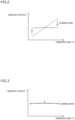
- a component (the second term in the Equation 3) proportional to 1/G R (T) of the error in the sensor output of the vibration-type angular rate sensor 100 (the term inversely proportional to the gain G R (T) dependent on temperature) is canceled by adding the second offset value based on the constant signal not dependent on temperature, whereby the sensor output (a dotted line in FIG. 2 ) having properties dependent on temperature becomes substantially constant (a solid line in FIG. 2 ).
- the sensor output that has been made substantially constant microscopically has properties (a dotted line in FIG. 3 ) dependent on temperature.
- a component (the first term in the Equation 3) proportional to 1/G R 2 (T) of the sensor output of the vibration-type angular rate sensor 100 (the term inversely proportional to the second power of the gain G R (T) dependent on temperature) is also canceled by adding the first offset value based on the output of the primary-side control circuit 2 dependent on temperature, whereby the sensor output becomes non-dependent on temperature and substantially constant (a solid line in FIG. 3 ). Consequently, the accuracy of the correction can be increased.
- the signal is a continuous value so that the sensor output of the vibration-type angular rate sensor 100 can be restrained from changing in a step manner (the sensor output can be a continuous value), unlike the case where the sensor output is corrected in a digital manner (the signal is a discrete value).
- the following describes the offset values in the first embodiment in which the primary-side control circuit 2 does not switch between one set of electrodes 50 and another set of electrodes 50 as electrodes that induce the primary vibration in the vibrator 1, and the secondary-side control circuit 3 does not switch between the another set of electrodes and the one set of electrodes as electrodes that detect the secondary vibration in the vibrator 1.
- a bias component (vertical axis) of angular velocity detected by the vibration-type angular rate sensor 100 generally varies in accordance with a change of temperature (horizontal axis). Also, variation of the bias component before the switching (P in FIG. 4 ) is different from variation the bias component after the switching (S in FIG. 4 ).
- a temperature variation of the sensor output (P in FIG. 5 ) can be reduced by adding the first and second offset values to cancel first and second terms of the aforementioned Equation 3 before the switching as shown in FIG. 5 . Also, a temperature variation of the sensor output (S in FIG.
- the temporal first offset value a1 and the temporal second offset value a2 are determined before and after the switching to minimize the temperature variation component of difference between bias components before and after the switching with polarities of the offset values before and after the switching being inverted with respect to each other as shown in FIG. 6(a) . If the temporal first offset value a1 and the temporal second offset value a2 are used before the switching, the first and second terms of the aforementioned Equation 3 are not canceled, and as a result the bias component has a gradient in accordance with temperature before the switching.
- the bias component has a gradient in accordance with temperature after the switching.
- the temporal first offset value b1 and the temporal second offset value b2 which are offset with respect to a median (M in FIG. 4 between the variation of the bias component before the switching (P in FIG. 4 ) and the variation of the bias component after the switching (S in FIG. 4 )), are determined to cancel the first and second terms of the aforementioned Equation 3 as shown in FIG. 6(b).
- the first offset value before the switching is a1 + b1
- the second offset value before the switching is a2 + b2
- the first offset value after the switching is -a1 + b1
- the second offset value after the switching is -a2 + b2.
- the first offset values before and after the switching become symmetrical with respect to the temporal first offset value b1, which is offset with respect to the median
- the second offset values before and after the switching become symmetrical with respect to the second offset value b2, which is offset with respect to the median.
- a Q-value (a dimensionless number indicating a vibration state) generally has properties inversely proportional to temperature.
- the primary-side control circuit 2 is configured to switch between one set of electrodes 50 and another set of electrodes 50 as electrodes that induce the primary vibration in the vibrator 1
- the secondary-side control circuit 3 is configured to switch between the another set of electrodes and the one set of electrodes as electrodes that detect the secondary vibration in the vibrator, and the offset value after the switching and the offset value before the switching are symmetrical values with respect to a predetermined reference value.
- the offset values before and after the switching are symmetrical values with respect to a predetermined reference value, it is possible to prevent that symmetry of control of the vibration-type angular rate sensor 100 before and after the switching is broken. Consequently, it is possible to preventing increase of a temperature variation component of residual bias that cannot be completely canceled.
- the secondary-side control circuit 3 includes a loop filter 34 in the closed control loop, and the sensor output is corrected by adding the offset value to an input of the loop filter 34.
- the output of the closed control loop corresponds to an output of the loop filter.
- the output of the loop filter is inversely proportional to the gain (gain) of the temperature-dependent vibrator 1 due to the feedback operation of the closed control loop.
- an error caused by crosstalk that is inversely proportional to the first power and/or the second power of the gain of the vibrator 1, can be reduced by adding the offset value to the input of the loop filter 34.
- the offset value after the switching is -a, which is a value whose polarity is inverted from the offset value before the switching a. Accordingly, because the offset values before and after the switching are symmetrical values with respect to zero before and after the primary-side control circuit 2 switch between one set of electrodes 50 and another set of electrodes 50 as electrodes that induce the primary vibration in the vibrator 1, and the secondary-side control circuit 3 can switch between the another set of electrodes and the one set of electrodes as electrodes that detect the secondary vibration in the vibrator 1, it is possible to prevent that symmetry of control of the vibration-type angular rate sensor 100 before and after the switching is broken.
- the offset value before the switching is a + b
- the offset value after the switching is -a + b
- a is a temporary offset before the switching
- -a is a temporary offset value after the switching
- b is a temporary offset value that is offset with respect to a median between the sensor output before the switching and the sensor output after the switching.
- the offset values before and after the switching are symmetrical values with respect to b before and after the primary-side control circuit 2 switch between one set of electrodes 50 and another set of electrodes 50 as electrodes that induce the primary vibration in the vibrator 1, and the secondary-side control circuit 3 can switch between the another set of electrodes and the one set of electrodes as electrodes that detect the secondary vibration in the vibrator 1, it is possible to prevent that symmetry of control of the vibration-type angular rate sensor 100 before and after the switching is broken.
- the offset values before and after the switching are symmetrical with the offset value b with respect to the median between the sensor output before the switching and the sensor output after the switching, it is possible to prevent that symmetry of control of the vibration-type angular rate sensor 100 before and after the switching is broken while reducing a gradient of a residual bias component with respect to an environment temperature.
- the sensor output is corrected, in a case of the analog correction of the sensor output, by adding, to the closed control loop of the secondary-side control circuit 3, a first offset value based on the output of the primary-side control circuit 2, which is inversely proportional to the temperature-dependent gain of the vibrator 1, for correction of the sensor output from the secondary-side control circuit 3 that is inversely proportional to a second power of the temperature-dependent gain of the vibrator 1, and a second offset value based on a constant signal that is independent of temperature for correction of the sensor output from the secondary-side control circuit 3 that is inversely proportional to the temperature-dependent gain of the vibrator 1, and by adjusting addition amounts of the first offset value and the second offset value.
- the output of the secondary-side control circuit 3 has properties inversely proportional to the gain of the vibrator 1 dependent on temperature.
- the output of the primary-side control circuit 2 also has properties inversely proportional to the gain of the vibrator 1 by the feedback operation of the closed control loop, and hence the output of the secondary-side control circuit 3 has properties inversely proportional to the second power of the gain of the vibrator 1 by adding, to the closed control loop of the secondary-side control circuit 3, the first offset value based on the output of the primary-side control circuit 2 having the properties inversely proportional to the gain of the vibrator 1.
- the sensor output is corrected, by adding, a first offset value corresponding to a second power of the gain of the vibrator and a second offset value corresponding to the gain of the vibrator, and by adjusting addition amounts of the first offset value and the second offset value, the sensor output can be subjected to correction that is inversely proportional to a first power of the gain of the vibrator and correction that is inversely proportional to a second power of the gain of the vibrator.
- the analog correction is applied to the sensor output by adjusting the addition amount of the first offset value based on the output of the primary-side control circuit 2, which is dependent on temperature and is inversely proportional to the temperature-dependent gain of the vibrator 1, so as to reduce A/GR 2 (T), and by adjusting the addition amount of the second offset value based on the constant signal that is independent of temperature so as to reduce B/G R (T); and A/G R 2 (T) and B/G R (T) are first and second terms, respectively, of Equation 3 representing a total error V Out_Total_Error of an error of the sensor output that occurs in the closed control loop of the secondary-side control circuit 3 due to an error signal that occurs from a circuit block included in the secondary-side control circuit 3 and an error of the sensor output that occurs in the closed control loop of the secondary-side control circuit 3 due to cross talk from the primary-side control circuit 2 to the secondary-side control circuit 3.
- Equation 3 where G R (T) is the gain of the vibrator 1, which is dependent on temperature, and A, B, and C are constant values independent of temperature.
- G R (T) is the gain of the vibrator 1, which is dependent on temperature
- A, B, and C are constant values independent of temperature.
- the vibrator 1 includes a ring-type vibrator 1.
- the ring-type vibrator 1 has a symmetrical shape, and hence a vibration mode in the primary-side control circuit 2 and a vibration mode in the secondary-side control circuit 3 are similar to each other.
- the present invention is applied to the vibration-type angular rate sensor 100 including the ring-type vibrator 1, it is not necessary to take into account the influence of a difference between the vibration modes, and hence the sensor output can be easily corrected.
- the primary-side control circuit 2 is configured to switch between parts of the vibrator 1 as parts that induce the primary vibration by switching the switch 41 and the switch 42
- the secondary-side control circuit 3 is configured to switch between parts of the vibrator 1 as parts that detect the secondary vibration by switching the switch 43 and the switch 44. Accordingly, the switching of the switches 41 to 43 allows the primary-side control circuit 2 to easily switch between one set of electrodes 50 and another set of electrodes 50 as electrodes that induce the primary vibration in the vibrator 1, and the secondary-side control circuit 3 to easily switch between the another set of electrodes and the one set of electrodes as electrodes that detect the secondary vibration in the vibrator 1.
- the following description describes a configuration of a vibration-type angular rate sensor 101 according to a second embodiment with reference to FIG. 8 .
- exemplary correction is described by digitally processing an output of the loop filter 23 of the primary-side control circuit 2.
- the vibration-type angular rate sensor 101 includes a vibrator 1, the primary-side control circuit 2, a secondary-side control circuit 3, an A-D conversion circuit 6, a correction arithmetic processing portion 7, and a D-A conversion circuit 8.
- Configurations of the vibrator 1, the primary-side control circuit 2 and the secondary-side control circuit 3 are similar to those of the first embodiment.
- the primary-side control circuit 2 is configured to switch between one set of electrodes 50 and another set of electrodes 50 as electrodes that induce the primary vibration in the vibrator 1
- the secondary-side control circuit 3 is configured to switch between the another set of electrodes and the one set of electrodes as electrodes that detect the secondary vibration in the vibrator 1.
- the primary-side control circuit 2 includes a switch 41 that is provided to the input side of a signal to the vibrator 1, and a switch 42 that is provided to the output side of the signal (output side of amplification circuit 21) from the vibrator 1.
- the secondary-side control circuit 3 includes a switch 43 that is provided to the input side of a signal to the vibrator 1, and a switch 44 that is provided to the output side of the signal (output side of amplification circuit 31) from the vibrator 1.
- the A-D conversion circuit 6 is configured to receive an analog signal dependent on temperature, output from the loop filter 23 of the primary-side control circuit 2, convert (quantize) the analog signal to a digital signal, and output the digital signal to the correction arithmetic processing portion 7.
- the correction arithmetic processing portion 7 is configured to output, to the D-A conversion circuit 8, an offset value for reducing an error in a sensor output caused by a temperature change in accordance with the quantized output (an output from the A-D conversion circuit 6) of the primary-side control circuit 2.
- the D-A conversion circuit 8 is configured to convert the offset value into an analog signal and add the analog signal to the input of a loop filter 34 of the secondary-side control circuit 3.
- the vibration-type angular rate sensor 101 is configured to correct the sensor output.
- offset values (y1, y2, ... , see FIG. 9 ) corresponding to temperatures (T1, T2, ... , see FIG. 9 ) are searched before and after the switching to minimize the residual temperature variation component of bias (difference between bias components before and after the switching) with polarities of the offset values before and after the switching being inverted similar to the aforementioned first embodiment.
- offset values (z1, z2, ... , see FIG. 9 ) which are offset with respect to a median between bias components before and after the switching, corresponding to temperatures (T1, T2, ... , see FIG. 9 ) are searched to reduce an error in the sensor output of the vibration-type angular rate sensor 101 (an error corresponding to the error defined by the aforementioned Equation 3) to zero or substantially zero.
- Equation 7 (l, m, and n are coefficients of constant values) is acquired (calculated) as y, which is an offset value that minimizes the residual temperature variation component of bias (difference between bias components before and after the switching), by performing polynomial approximation on data shown in FIG. 9 by a least-square method, where x is an output from the primary-side control circuit 2 (loop filter 23) quantized corresponding to each temperature.
- y is an offset value that minimizes the residual temperature variation component of bias (difference between bias components before and after the switching)
- Equation 8 is acquired as an offset value of the bias component before and the after switching, where x is the output from the primary-side control circuit 2 (loop filter 23) quantized corresponding to each temperature.
- the sensor output is corrected, in a case of digital correction of the sensor output, by quantizing the output of the primary-side control circuit 2, which is dependent on temperature and is inversely proportional to a temperature-dependent gain of the vibrator 1, and by adding, to the secondary-side control circuit 3, the offset value for reducing an error in the sensor output caused by a temperature change in accordance with the quantized output of the primary-side control circuit 2.
- the sensor output can be corrected simply by adding, to the secondary-side control circuit 3, the offset value for reducing the error in the sensor output caused by a temperature change to zero or substantially zero, and hence the configuration of the vibration-type angular rate sensor 101 can be simplified, unlike the case where an offset value other than the offset value based on the output of the primary-side control circuit 2 dependent on temperature is added.
- a disk-shaped, cup-shaped (wineglass-shaped), or octagon-shaped vibrator may be used so far as the vibrator has a symmetrical shape.
- the closed control loop includes the vibrator, the amplifier circuit, the synchronous detection circuit, the loop filter, the modulation circuit, and the drive circuit
- the present invention is not restricted to this.
- the control loop may include a structure other than the structure including the amplifier circuit, the synchronous detection circuit, the loop filter, the modulation circuit, and the drive circuit.
- the present invention is not limited to this.
- the first offset value before the switching can be a1
- the second offset value before the switching can be a2
- the first offset value after the switching can be -a1 whose polarity is inverted from the offset value before the switching a1
- the second offset value after the switching can be -a2 whose polarity is inverted from the offset value after the switching a2.
- the primary-side control circuit 2 switch between one set of electrodes 50 and another set of electrodes 50 as electrodes that induce the primary vibration in the vibrator 1
- the secondary-side control circuit 3 can switch between the another set of electrodes and the one set of electrodes as electrodes that detect the secondary vibration in the vibrator 1
- the second offset value for correction that is inversely proportional to a first power of the gain of the vibrator 1 are symmetrical with respect to zero (predetermined reference value), and as a result it is possible to prevent that symmetry of control of the vibration-type angular rate sensor before and after the switching is broken.
- the present invention is not limited to this.
- a median can be determined to cancel the first term in the aforementioned Equation 3 (in other words, the first offset value is fixed b1), the second offset value before the switching can be a2 + b2, and the second offset value after the switching can be -a2 + b2. That is, only the second offset values before and after the switching can be symmetrical with respect to a predetermined reference value.
- the present invention is not limited to this.
- the first and second offset values before and after the switching can be determined to reduce residual bias components to values close to the minimized residual bias component values before and after the switching.
- addition-subtraction amount adjusting circuits 4a and 4b, and the addition-subtraction amount adjusting circuits 5a and 5b are provided to output the offset value a + b and the offset value -a + b
- the present invention is not limited to this.
- any circuit can be provided as long as it can output signals corresponding to the offset value of a + b and the offset value of -a + b.
Landscapes
- Engineering & Computer Science (AREA)
- Physics & Mathematics (AREA)
- General Physics & Mathematics (AREA)
- Radar, Positioning & Navigation (AREA)
- Remote Sensing (AREA)
- Signal Processing (AREA)
- Gyroscopes (AREA)
Applications Claiming Priority (1)
| Application Number | Priority Date | Filing Date | Title |
|---|---|---|---|
| PCT/JP2021/033607 WO2023037559A1 (fr) | 2021-09-13 | 2021-09-13 | Capteur de vitesse angulaire du type à vibration |
Publications (2)
| Publication Number | Publication Date |
|---|---|
| EP4403875A1 true EP4403875A1 (fr) | 2024-07-24 |
| EP4403875A4 EP4403875A4 (fr) | 2025-09-10 |
Family
ID=85506236
Family Applications (1)
| Application Number | Title | Priority Date | Filing Date |
|---|---|---|---|
| EP21956854.0A Pending EP4403875A4 (fr) | 2021-09-13 | 2021-09-13 | Capteur de vitesse angulaire du type à vibration |
Country Status (7)
| Country | Link |
|---|---|
| US (1) | US20240384990A1 (fr) |
| EP (1) | EP4403875A4 (fr) |
| JP (1) | JP7600423B2 (fr) |
| CN (1) | CN117916555A (fr) |
| AU (1) | AU2021464033B2 (fr) |
| CA (1) | CA3232403A1 (fr) |
| WO (1) | WO2023037559A1 (fr) |
Families Citing this family (1)
| Publication number | Priority date | Publication date | Assignee | Title |
|---|---|---|---|---|
| JP7404123B2 (ja) * | 2020-03-24 | 2023-12-25 | 住友精密工業株式会社 | 振動型角速度センサ |
Family Cites Families (6)
| Publication number | Priority date | Publication date | Assignee | Title |
|---|---|---|---|---|
| JP3536497B2 (ja) * | 1995-12-21 | 2004-06-07 | 株式会社デンソー | 振動型角速度検出装置 |
| JP2009115559A (ja) | 2007-11-05 | 2009-05-28 | Sumitomo Precision Prod Co Ltd | 角速度センサ及び角速度センサを備えた電子機器 |
| JP5714388B2 (ja) * | 2011-04-01 | 2015-05-07 | シチズンホールディングス株式会社 | センサ駆動回路、及びそれを用いた物理量センサ |
| JP6463335B2 (ja) | 2014-02-26 | 2019-01-30 | 住友精密工業株式会社 | 振動型角速度センサ |
| JP7404123B2 (ja) * | 2020-03-24 | 2023-12-25 | 住友精密工業株式会社 | 振動型角速度センサ |
| JP6761140B1 (ja) * | 2020-03-24 | 2020-09-23 | 住友精密工業株式会社 | 振動型角速度センサ |
-
2021
- 2021-09-13 EP EP21956854.0A patent/EP4403875A4/fr active Pending
- 2021-09-13 CA CA3232403A patent/CA3232403A1/fr active Pending
- 2021-09-13 WO PCT/JP2021/033607 patent/WO2023037559A1/fr not_active Ceased
- 2021-09-13 CN CN202180102273.5A patent/CN117916555A/zh active Pending
- 2021-09-13 US US18/691,257 patent/US20240384990A1/en active Pending
- 2021-09-13 JP JP2023546726A patent/JP7600423B2/ja active Active
- 2021-09-13 AU AU2021464033A patent/AU2021464033B2/en active Active
Also Published As
| Publication number | Publication date |
|---|---|
| WO2023037559A1 (fr) | 2023-03-16 |
| AU2021464033A1 (en) | 2024-04-11 |
| CN117916555A (zh) | 2024-04-19 |
| CA3232403A1 (fr) | 2023-03-16 |
| AU2021464033B2 (en) | 2025-05-15 |
| JPWO2023037559A1 (fr) | 2023-03-16 |
| US20240384990A1 (en) | 2024-11-21 |
| JP7600423B2 (ja) | 2024-12-16 |
| EP4403875A4 (fr) | 2025-09-10 |
Similar Documents
| Publication | Publication Date | Title |
|---|---|---|
| EP3112804B1 (fr) | Capteur de vitesse angulaire du type à vibration | |
| CN101023367B (zh) | 连续校准的磁场传感器 | |
| EP2351982A1 (fr) | Capteur de vitesse angulaire | |
| CN115315612A (zh) | 振动型角速度传感器 | |
| EP4130661B1 (fr) | Capteur de vitesse angulaire du type à vibration | |
| EP4403875A1 (fr) | Capteur de vitesse angulaire du type à vibration | |
| CN115280100A (zh) | 方位角姿势角测量装置 | |
| JP5128910B2 (ja) | 温度補正装置及び温度補正方法 | |
| CN116184815B (zh) | 消除光纤陀螺复位误差的闭环控制方法及系统 | |
| EP0520485B1 (fr) | Dispositif de retard réglable | |
| JPH06294664A (ja) | 非線形回路 | |
| JP3464516B2 (ja) | ロードセルの零点変化検出装置及びロードセルの零点変化補正装置 | |
| JPH037072B2 (fr) | ||
| JP2822829B2 (ja) | 信号入力装置 | |
| JP2001242008A (ja) | 温度補正手段を用いてクリープ補正をする電子秤 | |
| WO2023037554A1 (fr) | Capteur de vitesse angulaire de type oscillatoire | |
| SU1446691A2 (ru) | Преобразователь угла поворота вала в код | |
| JPH08126187A (ja) | ディジタル形保護継電器の保護方法 | |
| JPH0258951A (ja) | 位相検波装置 | |
| JPH0257851B2 (fr) | ||
| JPH0342513A (ja) | 差動トランス変換方式 | |
| JPH01318980A (ja) | 磁場計測装置 |
Legal Events
| Date | Code | Title | Description |
|---|---|---|---|
| STAA | Information on the status of an ep patent application or granted ep patent |
Free format text: STATUS: THE INTERNATIONAL PUBLICATION HAS BEEN MADE |
|
| PUAI | Public reference made under article 153(3) epc to a published international application that has entered the european phase |
Free format text: ORIGINAL CODE: 0009012 |
|
| STAA | Information on the status of an ep patent application or granted ep patent |
Free format text: STATUS: REQUEST FOR EXAMINATION WAS MADE |
|
| 17P | Request for examination filed |
Effective date: 20240305 |
|
| AK | Designated contracting states |
Kind code of ref document: A1 Designated state(s): AL AT BE BG CH CY CZ DE DK EE ES FI FR GB GR HR HU IE IS IT LI LT LU LV MC MK MT NL NO PL PT RO RS SE SI SK SM TR |
|
| DAV | Request for validation of the european patent (deleted) | ||
| DAX | Request for extension of the european patent (deleted) | ||
| A4 | Supplementary search report drawn up and despatched |
Effective date: 20250807 |
|
| RIC1 | Information provided on ipc code assigned before grant |
Ipc: G01C 19/5776 20120101AFI20250801BHEP Ipc: G01C 19/567 20120101ALI20250801BHEP |