EP4403982A2 - Intraokularlinsen zur verringerung von negativer dysphotopsie - Google Patents
Intraokularlinsen zur verringerung von negativer dysphotopsie Download PDFInfo
- Publication number
- EP4403982A2 EP4403982A2 EP24180170.3A EP24180170A EP4403982A2 EP 4403982 A2 EP4403982 A2 EP 4403982A2 EP 24180170 A EP24180170 A EP 24180170A EP 4403982 A2 EP4403982 A2 EP 4403982A2
- Authority
- EP
- European Patent Office
- Prior art keywords
- optical zone
- optic
- attenuation
- ophthalmic lens
- edge
- Prior art date
- Legal status (The legal status is an assumption and is not a legal conclusion. Google has not performed a legal analysis and makes no representation as to the accuracy of the status listed.)
- Pending
Links
Images




Classifications
-
- A—HUMAN NECESSITIES
- A61—MEDICAL OR VETERINARY SCIENCE; HYGIENE
- A61F—FILTERS IMPLANTABLE INTO BLOOD VESSELS; PROSTHESES; DEVICES PROVIDING PATENCY TO, OR PREVENTING COLLAPSING OF, TUBULAR STRUCTURES OF THE BODY, e.g. STENTS; ORTHOPAEDIC, NURSING OR CONTRACEPTIVE DEVICES; FOMENTATION; TREATMENT OR PROTECTION OF EYES OR EARS; BANDAGES, DRESSINGS OR ABSORBENT PADS; FIRST-AID KITS
- A61F2/00—Filters implantable into blood vessels; Prostheses, i.e. artificial substitutes or replacements for parts of the body; Appliances for connecting them with the body; Devices providing patency to, or preventing collapsing of, tubular structures of the body, e.g. stents
- A61F2/02—Prostheses implantable into the body
- A61F2/14—Eye parts, e.g. lenses or corneal implants; Artificial eyes
- A61F2/16—Intraocular lenses
- A61F2/1613—Intraocular lenses having special lens configurations, e.g. multipart lenses; having particular optical properties, e.g. pseudo-accommodative lenses, lenses having aberration corrections, diffractive lenses, lenses for variably absorbing electromagnetic radiation, lenses having variable focus
- A61F2/1616—Pseudo-accommodative, e.g. multifocal or enabling monovision
- A61F2/1618—Multifocal lenses
-
- A—HUMAN NECESSITIES
- A61—MEDICAL OR VETERINARY SCIENCE; HYGIENE
- A61F—FILTERS IMPLANTABLE INTO BLOOD VESSELS; PROSTHESES; DEVICES PROVIDING PATENCY TO, OR PREVENTING COLLAPSING OF, TUBULAR STRUCTURES OF THE BODY, e.g. STENTS; ORTHOPAEDIC, NURSING OR CONTRACEPTIVE DEVICES; FOMENTATION; TREATMENT OR PROTECTION OF EYES OR EARS; BANDAGES, DRESSINGS OR ABSORBENT PADS; FIRST-AID KITS
- A61F2/00—Filters implantable into blood vessels; Prostheses, i.e. artificial substitutes or replacements for parts of the body; Appliances for connecting them with the body; Devices providing patency to, or preventing collapsing of, tubular structures of the body, e.g. stents
- A61F2/02—Prostheses implantable into the body
- A61F2/14—Eye parts, e.g. lenses or corneal implants; Artificial eyes
- A61F2/16—Intraocular lenses
- A61F2/1613—Intraocular lenses having special lens configurations, e.g. multipart lenses; having particular optical properties, e.g. pseudo-accommodative lenses, lenses having aberration corrections, diffractive lenses, lenses for variably absorbing electromagnetic radiation, lenses having variable focus
- A61F2/1637—Correcting aberrations caused by inhomogeneities; correcting intrinsic aberrations, e.g. of the cornea, of the surface of the natural lens, aspheric, cylindrical, toric lenses
- A61F2/164—Aspheric lenses
-
- A—HUMAN NECESSITIES
- A61—MEDICAL OR VETERINARY SCIENCE; HYGIENE
- A61F—FILTERS IMPLANTABLE INTO BLOOD VESSELS; PROSTHESES; DEVICES PROVIDING PATENCY TO, OR PREVENTING COLLAPSING OF, TUBULAR STRUCTURES OF THE BODY, e.g. STENTS; ORTHOPAEDIC, NURSING OR CONTRACEPTIVE DEVICES; FOMENTATION; TREATMENT OR PROTECTION OF EYES OR EARS; BANDAGES, DRESSINGS OR ABSORBENT PADS; FIRST-AID KITS
- A61F2/00—Filters implantable into blood vessels; Prostheses, i.e. artificial substitutes or replacements for parts of the body; Appliances for connecting them with the body; Devices providing patency to, or preventing collapsing of, tubular structures of the body, e.g. stents
- A61F2/02—Prostheses implantable into the body
- A61F2/14—Eye parts, e.g. lenses or corneal implants; Artificial eyes
- A61F2/16—Intraocular lenses
- A61F2002/1696—Having structure for blocking or reducing amount of light transmitted, e.g. glare reduction
-
- A—HUMAN NECESSITIES
- A61—MEDICAL OR VETERINARY SCIENCE; HYGIENE
- A61F—FILTERS IMPLANTABLE INTO BLOOD VESSELS; PROSTHESES; DEVICES PROVIDING PATENCY TO, OR PREVENTING COLLAPSING OF, TUBULAR STRUCTURES OF THE BODY, e.g. STENTS; ORTHOPAEDIC, NURSING OR CONTRACEPTIVE DEVICES; FOMENTATION; TREATMENT OR PROTECTION OF EYES OR EARS; BANDAGES, DRESSINGS OR ABSORBENT PADS; FIRST-AID KITS
- A61F2240/00—Manufacturing or designing of prostheses classified in groups A61F2/00 - A61F2/26 or A61F2/82 or A61F9/00 or A61F11/00 or subgroups thereof
- A61F2240/001—Designing or manufacturing processes
-
- A—HUMAN NECESSITIES
- A61—MEDICAL OR VETERINARY SCIENCE; HYGIENE
- A61F—FILTERS IMPLANTABLE INTO BLOOD VESSELS; PROSTHESES; DEVICES PROVIDING PATENCY TO, OR PREVENTING COLLAPSING OF, TUBULAR STRUCTURES OF THE BODY, e.g. STENTS; ORTHOPAEDIC, NURSING OR CONTRACEPTIVE DEVICES; FOMENTATION; TREATMENT OR PROTECTION OF EYES OR EARS; BANDAGES, DRESSINGS OR ABSORBENT PADS; FIRST-AID KITS
- A61F2250/00—Special features of prostheses classified in groups A61F2/00 - A61F2/26 or A61F2/82 or A61F9/00 or A61F11/00 or subgroups thereof
- A61F2250/0014—Special features of prostheses classified in groups A61F2/00 - A61F2/26 or A61F2/82 or A61F9/00 or A61F11/00 or subgroups thereof having different values of a given property or geometrical feature, e.g. mechanical property or material property, at different locations within the same prosthesis
- A61F2250/0053—Special features of prostheses classified in groups A61F2/00 - A61F2/26 or A61F2/82 or A61F9/00 or A61F11/00 or subgroups thereof having different values of a given property or geometrical feature, e.g. mechanical property or material property, at different locations within the same prosthesis differing in optical properties
-
- G—PHYSICS
- G02—OPTICS
- G02C—SPECTACLES; SUNGLASSES OR GOGGLES INSOFAR AS THEY HAVE THE SAME FEATURES AS SPECTACLES; CONTACT LENSES
- G02C7/00—Optical parts
- G02C7/02—Lenses; Lens systems ; Methods of designing lenses
- G02C7/024—Methods of designing ophthalmic lenses
- G02C7/028—Special mathematical design techniques
Definitions
- Negative dysphotopsia is characterized by subjective reports and complaints from patients having an intraocular lens (IOL) implanted, where the complaints describe the presence of a dark shadow in the far periphery.
- IOL intraocular lens
- the presence of ND is likely caused by absence of light in the retinal interval between light passing through and refracted by the IOL (e.g., at lower angles of incidence) and rays missing the IOL (e.g., at higher angles of incidence).
- Posterior capsule opacification results from lens fibers formed in the equatorial zone that migrate over the posterior side of an IOL, which can result in reduced visual quality and potentially requires a secondary intervention with an NdYAG laser. While results vary, and improved IOL designs have substantially reduced the rate of PCO the last few decades, it is still a significant issue negatively affecting the results of cataract surgery.
- the current state of the art for PCO prevention is a PCO edge covering the full IOL (360 degrees) with an angle of around 90-110 degrees, including on the haptics.
- An example ophthalmic lens may include an optic including an anterior surface defining an anterior side of the optic, and a posterior surface defining a posterior side of the optic, wherein the posterior surface opposes the anterior surface.
- the lens includes a central optical zone disposed about the optical axis and an attenuation optical zone disposed about the central optical zone, wherein the attenuation optical zone is contiguous with the central optical zone, and wherein optical power of the ophthalmic lens is gradually reduced within the attenuation optical zone.
- the optical power of the ophthalmic lens may gradually reduce to zero at an outermost edge of the attenuation optical zone.
- the outermost edge of the attenuation optical zone may be configured to minimize ray deviation as compared to a ray that misses the optic.
- a transition between the central optical zone and the attenuation optical zone may be smooth and continuous.
- a slope of the optic may be the same at a beginning of the attenuation optical zone and an end of the central optical zone.
- the attenuation optical zone may be configured to eliminate discontinuity in angular deviation of chief rays passing through the optic. Additionally, the attenuation optical zone may increase a diameter of the optic by between about 0.5 millimeter (mm) and about 3 mm. The diameter of the optic may between about 6 mm and about 8 mm.
- the optic may define an edge, and wherein an angle of the edge is 90 degrees or less.
- an ophthalmic lens comprising an optic, the optic including a central optical zone disposed about the optical axis and an attenuation optical zone disposed about the central optical zone, wherein the attenuation optical zone is contiguous with the central optical zone, may be carried out with a method comprising: establishing a starting point for the attenuation optical zone, the starting point having the same thickness and the same slope as an ending point for the central optical zone; establishing an ending point for the attenuation optical zone, wherein the ending point for the attenuation optical zone is at an edge of the optic; and optimizing splines between the starting and ending points for the attenuation optical zone, wherein the splines are optimized using a merit function.
- the splines may be optimized to provide minimal total slope deviation.
- the slope of the ending point for the attenuation optical zone may be 90 degrees or less.
- the attenuation optical zone may be configured to eliminate discontinuity in angular deviation of chief rays passing through the optic.
- Ranges may be expressed herein as from “about” one particular value, and/or to "about” another particular value. When such a range is expressed, an aspect includes from the one particular value and/or to the other particular value. Similarly, when values are expressed as approximations, by use of the antecedent "about,” it will be understood that the particular value forms another aspect. It will be further understood that the endpoints of each of the ranges are significant both in relation to the other endpoint, and independently of the other endpoint. While implementations are described for intraocular lenses, it will become evident to those skilled in the art that the implementations are not limited thereto, but are applicable for other ophthalmic lenses.
- an IOL that substantially reduces negative dysphotopsia through changes of IOL design in the form of introducing an attenuation optical zone (also referred to herein as "attenuation zone"). While conventional IOLs on the market have an optical zone size of about 5 or 6 mm in diameter (and nothing outside the edge of that zone), the IOLs described herein increase the optical diameter by about 0.5-3 mm, bringing the total optical diameter of the IOL potentially up to 8 mm.
- the purpose of the attenuation zone is to act as a bridge between light at angles where the light is refracted by the IOL and where the light misses the IOL.
- the attenuation zone gradually decreases the deviation of light with higher angles, until light at angles just at the edge of the IOL are almost not refracted at all, making the difference to light at angles missing the IOL minimal.
- An IOL that reduces or attenuates ND as described herein can include: a central optical zone for central vision and/or functional peripheral vision; and an attenuation optical zone that gradually reduces the power in the outer or peripheral part of the IOL.
- a central optical zone for central vision and/or functional peripheral vision
- an attenuation optical zone that gradually reduces the power in the outer or peripheral part of the IOL.
- monofocal, multifocal, and Extended Depth of Focus (EDoF) IOLs are used for central vision.
- functional peripheral vision is vision within less than about 40 degrees of the visual field.
- the attenuation zone does not contribute to either central vision or functional peripheral vision (e.g., vision below 40 degrees of the visual field) unless the pupil is exceptionally large.
- the IOL that reduces or attenuates ND can include a sharp IOL edge design.
- the central optical zone of the IOL is independent of the attenuation optical zone. Accordingly, this disclosure contemplates that the attenuation zone and/or the sharp edge design described herein can be added to any IOL design because neither affects central vision or peripheral vision below 40 degrees. Accordingly, the attenuation zone and/or sharp edge design can be added to refractive and diffractive lOLs as well as to monofocal, multifocal and extended range of vision IOLs.
- an IOL that increases pressure at the posterior capsular bend, which reduces the possibility of cell growth and migration onto the optics of the IOL. Such cell growth and migration reduces the structure disposed about the peripheral region of the optic, which results in the presence of glare or posterior capsular opacification (PCO).
- An IOL that reduces the risk of PCO can include one or more of the following: a sharper edge design, an enlarged optical zone, and/or an increased vault height.
- the terms “about” or “approximately”, when used in reference to an angle mean within plus or minus 1 degree.
- the terms “about” or “approximately”, when used in reference to a linear dimension mean within plus or minus 5 % of the value of the referenced linear dimension.
- the terms "light” or “visible light” mean electromagnetic radiation within the visible waveband, for example, electromagnetic radiation with a wavelength in a vacuum that is between 390 nanometers and 780 nanometers.
- the term "optical power" of a lens or optic means the ability of the lens or optic to converge or diverge light to provide a focus (real or virtual) when disposed within a media having a refractive index of 1.336 (generally considered to be the refractive index of the aqueous and vitreous humors of the human eye), and is specified in reciprocal meters or Diopters (D). See ISO 11979-2.
- focus or "focal length” of a lens or optic is the reciprocal of the optical power.
- power of a lens or optic means optical power. Except where noted otherwise, optical power (either absolute or add power) of an intraocular lens or associated optic is from a reference plane associated with the lens or optic (e.g., a principal plane of an optic).
- the term “near vision” means vision produced by an eye that allows a subject to focus on objects that are at a distance of 40 cm or closer to a subject, typically within a range of 25 cm to 33 cm from the subject, which corresponds to a distance at which a subject would generally place printed material for the purpose of reading.
- intermediate vision means vision produced by an eye that allows a subject to focus on objects that are located between 40 cm and 2 meters from the subject.
- disant vision means vision produced by an eye that allows a subject to focus on objects that are at a distance that is greater than 2 meters, typically at a distance of about 5 meters from the subject, or at a distance of about 6 meters from the subject, or greater.
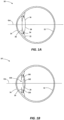
- FIG. 1A a cross-sectional view of a phakic eye containing the natural crystalline lens is shown in which an eye 10 includes a retina 12 that receives light in the form of an image produced when light from an object is focused by the combination of the optical powers of a cornea 14 and a natural crystalline lens 16.
- the cornea 14 and lens 16 are generally disposed about an optical axis (OA).
- OA optical axis
- the natural lens 16 is enclosed within a capsular bag 20, which is a thin membrane attached to a ciliary muscle 22 via zonules 24.
- An iris 26, disposed between the cornea 14 and the natural lens 16, provides a variable pupil that dilates under lower lighting conditions (mesopic or scotopic vision) and constricts under brighter lighting conditions (photopic vision).
- the ciliary muscle 22, via the zonules 24, controls the shape and position of the natural lens 16, allowing the eye 10 to focus on both distant and near objects. It is generally understood that distant vision is provided when the ciliary muscle 22 is relaxed, wherein the zonules 24 pull the natural lens 16 so that the capsular bag 20 and lens 16 are generally flatter and provide a longer focal length (lower optical power). It is generally understood that near vision is provided when the ciliary muscle contracts, thereby relaxing the zonules 24 and allowing the capsular bag 20 and lens 16 to return to a more rounded state that produces a shorter focal length (higher optical power).
- the intraocular lens 100 can include an optic 102 and haptics 103, the haptics 103 being configured to at least generally center the optic 102 within the capsular bag 20, provide transfer of ocular forces to the optic 102, and the like.
- Numerous configurations of haptics 103 relative to optic 102 are well known within the art, and the optics described herein can generally include any of these haptic configurations.
- the ophthalmic lens is an IOL.
- the ophthalmic lens can be a refractive or diffractive IOL.
- the ophthalmic lens can be a monofocal, multifocal, or extended range of vision IOL.
- the IOL types described above are only provided as examples and that the ophthalmic lens can be an IOL other than one of the types provided as examples.
- the IOL described with regard to Figs. 2A-2C can reduce the rate of PCO. Alternatively or additionally, the IOL described with regard to Figs. 2A-2C can reduce ND.
- the ophthalmic lens can include an optic 200 including an anterior surface 202 defining an anterior side of the optic 200 and a posterior surface 204 defining a posterior side of the optic 200.
- the posterior surface 204 can oppose the anterior surface 202.
- the optic 200 can also include an edge 210 arranged between the anterior and posterior surfaces 202, 204.
- the optical axis is labelled "OA" in Fig. 2A and extends through about the center of the optic 200.
- the rate of PCO can be reduced by including one or more of the following elements: a sharper edge design (e.g., the edge 210 shown in Figs. 2A and 2B ), an enlarged optical zone (e.g., including the attenuation optical zone 220 in addition to the central optical zone 225 shown in Figs. 2A and 2C ), and/or an increased vault height (e.g., as shown in Figs. 2A and 3 ).
- edge design existing commercial IOLs do not include the sharper edge designs described herein (e.g., less than about 90 degrees).
- the edge of an IOL would have an angle of 107 degrees, 102 degrees, and 99 degrees, respectively, following a radius of curvature of 10 mm, 15 mm, and 20 mm, respectively, at 6 mm optic diameter. This is shown by Figs. 12A-12C . These angles are greater than 90, and bad for PCO. An IOL with an edge angle of 90 degrees is shown in Fig. 12D for comparison.
- ND can be reduced by including one or more of the following elements: an enlarged optical zone (e.g., including the attenuation optical zone 220 in addition to the central optical zone 225 shown in Figs.
- ND can be eliminated using a sharp edge design with an angle of about 90 degrees. Using an angle of about 90 degrees may reduce manufacturing challenges depending on the technique used for producing the IOL. Alternatively, ND can be eliminated using a sharp edge design with an angle of less than 90 degrees.
- the IOLs described herein can include a sharper edge design as compared to conventional lOLs.
- This disclosure contemplates that the sharper edge can be provided along the entire edge - 360 degrees - of the optic.
- the edge 210 and the posterior surface 204 can form an angle (e.g., angle ⁇ ).
- the edge with angle ⁇ can be configured to increase pressure on a capsular bend in a subject's eye.
- angle ⁇ can be 90 degrees.
- the edge 210 is parallel to the optical axis of the ophthalmic lens.
- An IOL with angle ⁇ equal to about 90 degrees can decrease or even eliminate ND and reduce PCO.
- angle ⁇ can be less than 90 degrees such as between 45 degrees and 90 degrees.
- the edge 210 is not parallel to the optical axis of the ophthalmic lens.
- the edge of an IOL is cut such that the angle formed between the edge and posterior surface is greater than 90 degrees but less than 110 degrees. Examples where the edge of an existing IOL would have an angle between 99 and 107 degrees are discussed above with regard to Figs. 12A-12C .
- Fig. 2B is an enlarged view of the portion of the optic 200 in the dashed box 215, which includes the edge 210, shown in Fig. 2A .
- Fig. 2B illustrates angle ⁇ .
- the angle ⁇ can be between 45 degrees and 90 degrees.
- the angle ⁇ can be less than or equal to about 90 degrees. In some implementations, the angle ⁇ can be less than about 90 degrees. In some implementations, the angle ⁇ can be less than or equal to about 85 degrees. In some implementations, the angle ⁇ can be less than or equal to about 80 degrees. In some implementations, the angle ⁇ can be less than or equal to about 70 degrees. In some implementations, the angle ⁇ can be less than or equal to about 60 degrees. In some implementations, the angle ⁇ can be less than or equal to about 50 degrees. Having an angle ⁇ as described above (e.g., a sharper edge design) results in a higher pressure at the capsular bend, which lowers risk of PCO.
- the angle ⁇ as described above reduces ND.
- a sharp angle of the edge 210 can be achieved by enlarging the optical zone size (as described below) and/or having an anterior side with an equal or smaller diameter as compared to a posterior side.
- the diameter of the anterior surface 202 that forms the anterior side is less than the diameter of the posterior surface 204 that forms the posterior side as shown in Fig. 2A , which results in a sharp edge angle of less than 90 degrees.
- the diameter of the anterior surface 202 that forms the anterior side would be equal to the diameter of the posterior surface 204 that forms the posterior side.
- the IOLs described herein can include an enlarged optical zone as compared to conventional lOLs.
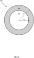
- the ophthalmic lens can include a central optical zone 225 disposed about the optical axis and an attenuation optical zone 220 disposed about the central optical zone 225. These zones are shown in Figs. 2A and 2C .
- the central optical zone 225 and the attenuation optical zone 220 are defined by respective shapes of the anterior and posterior surfaces 202, 204 of the optic 200.
- the shapes or contours of the anterior and posterior surfaces 202, 204 control the design parameters (e.g., height, thickness, width, curvature, etc.) of the optic 200.
- the central optical zone 225 extends radially outward from about the center of the optic (e.g., where the optical axis intersects the optic 200 as shown in Fig. 2A ) to the radius (R') as shown in Fig. 2C .
- the central optical zone 225 is configured for central vision and/or functional peripheral vision, e.g., the central optical zone 225 is optimized for central vision and/or functional peripheral vision, which is below 40 degrees of the visual field. In some implementations, the central optical zone 225 has a diameter of about 5-6 mm).
- the IOLs described herein can include the attenuation optical zone 220, which is in addition to the central optical zone 225. Having an attenuation zone as described herein results in a higher pressure at the capsular bend, which lowers risk of PCO. Alternatively or additionally, the attenuation zone reduces ND. The attenuation optical zone also facilitates the provision of a sharper edge design as described above.
- the attenuation optical zone 220 is contiguous with the central optical zone 225.
- the central optical zone 225 and the attenuation optical zone 220 can optionally be concentric.
- the attenuation optical zone 220 is configured to not affect central vision and/or peripheral vision below 40 degrees Additionally, the transition between the central optical zone 225 and attenuation optical zone 220 can be smooth and continuous.
- the optic 200 can be configured such that the start (or beginning) of the optical attenuation zone 220 (e.g., the nearest attenuation region radially outward from the center of the optic) has the same coordinate and the same slope as the end of the central optical zone 225 (e.g., the most distant central region radially outward from the center of the optic 200). Design of the optic is described in further detail below with regard to Figs. 4-11 . Therefore, the central and attenuation optical zones connect seamlessly.
- the attenuation optical zone 220 extends radially outward from about the central optical zone 225 from radius (R') to radius (R) as shown in Fig. 2C .
- optical power can be gradually reduced within the attenuation optical zone 220.
- optical power of the ophthalmic lens can optionally be gradually reduced to zero at an outermost edge of attenuation optical zone 220 (e.g., at edge 210 as shown in Figs. 2A and 2B ).
- Gradual reduction in optical power is now described with reference to Figs. 5 and 7 . Normally, as the angle of the chief rays increase, the angular deviation of the chief rays by the IOL increases as well.
- Fig. 7 illustrates gradual reduction in optical power. Increasing angular deviation stops at about 55 degrees, which corresponds to a higher angle outside of the eye. Then, the angular deviation decreases gradually (e.g., not suddenly as shown in Fig. 5 ).
- the optic and particularly the attenuation optical zone 220, is configured to eliminate discontinuity in angular deviation of chief rays passing through the optic 200. A gradual reduction in optical power is therefore shown in Fig. 7 .
- the attenuation optical zone 220 increases the size of the optical zone of the IOL.
- the central optical zone 225 has a diameter of about 5-6 mm).
- the attenuation optical zone 220 can increase the diameter of the optic 200 by between about 0.5 mm and about 3 mm, for example, to achieve an optical diameter of between about 6 mm and about 8 mm.
- the diameter of the optic can optionally be 6.0, 6.5 mm, 7, mm, 7.5 mm, or 8 mm. Exceeding 8 mm diameters adds a lot of volume and may create problems with fit.
- the larger optical zone size increases the ratio of the optical zone to the anterior capsulorhexis, which facilitates firmly attaching the remaining anterior part of the capsule to the anterior side of the IOL. This results in increasing the pressure on the posterior capsular bend, which lowers the risk of PCO.
- the size of the optical zone is limited by the need to keep the optic volume low, which is an untenable goal with a full power IOL, e.g., at 8 mm diameter.
- the full optical zone does not need to provide the full power, since the outer or peripheral optical portions of the IOL (e.g., the attenuation optical zone 220 shown in Figs.
- optical power of the IOL can be gradually reduced in the attenuation zone, which results in lower optic volume.
- optical power can be reduced down to zero Diopter (D) at the edge of the optical zone.
- D Diopter
- improved PCO protection can be achieved without the need for excessive volume.
- optical power is gradually reduced in the attenuation optical zone 220, e.g., the radii between about 2.5 mm and 4 mm.
- the IOL has both an enlarged optical zone (e.g., including central and attenuation optical zones as shown in Figs. 2A and 2C ) and an increased vault height (e.g., as shown in Figs. 2A and 2C ).
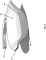
- an optic 300 including an anterior surface 302 defining an anterior side of the optic 300 and a posterior surface 304 defining a posterior side of the optic 300.
- the posterior surface 304 opposes the anterior surface 302.
- the optic 300 has a negative shape factor. More negative shape factor, meaning more posterior, means higher vault height.
- the optic 300 also includes a haptic 350 attached to the optic 300. Haptics are configured to generally center the optic 300 within the capsular bag (e.g., capsular bag 20 shown in Figs. 1A-1B ) and/or transfer ocular forces to the optic 300.
- the use of haptics with IOLs are well known in the art. This disclosure contemplates using haptic configurations known in the art with IOLs described herein.
- the optic 300 includes an edge 310 arranged between the anterior and posterior surfaces 302, 304. The edge 310 is cut parallel to the optical axis of the ophthalmic lens. In other words, the edge 310 and the posterior surface 304 form an angle of about 90 degrees. As described herein, the angle formed by the edge 310 and the posterior surface 304 can be between 45 degrees and 90 degrees.
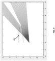
- Fig. 4 a diagram illustrating the chief ray passing through the center of a pupil at an angle between 50 and 85 degrees, for a conventional biconvex IOL 400 is described.
- Fig. 4 is useful for understanding the cause of ND.
- Fig. 4 illustrates the path of the chief rays passing through the center of the pupil at angles between 50 and 85 degrees.
- the chief rays are either refracted by the biconvex IOL 400 or miss the biconvex IOL 400. Rays hitting the edge of the biconvex IOL 400 are assumed to be scattered/blocked, as the edge is often frosted. From Fig. 4 , it is clear that there is an angular interval that will be perceived as a shadow.
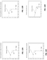
- the behavior of the chief ray can be quantified as shown in Fig. 5 , which illustrates chief ray deviation as a function of angle for the biconvex IOL of Fig. 4 .
- the discontinuity arises between about 63 degrees, where the deviation is 9 degrees, and about 65 degrees, where the chief ray pass the IOL creating a shadow of about 11 degrees in the extreme case, with partial illumination of the shadow area at larger pupil sizes.
- an attenuation zone e.g., the attenuation optical zone 220 shown in Figs. 2A and 2C
- the central optical part e.g., the central optical zone 225 shown in Figs. 2A and 2C .
- an IOL configuration can include the following design features.
- the beginning of the attenuation zone can be smooth and continuous, meaning that the height and the slope in the beginning of the attenuation zone is the same as the height and the slope in the end of the central optical part. In other words, the transition between the zones is smooth and continuous.
- the end of the attenuation zone can introduce minimal ray deviations as compared to a chief ray missing the IOL. Additionally, the end of the attenuation zone can have a predetermined position, thickness and slope.
- the attenuation zone (e.g., size, dimensions, etc.) itself can be evaluated or optimized in order to fulfill the criteria above while minimizing ray deviations and slope variability within the zone.
- a number of attenuation zone design parameters are discussed above. These design parameters include, but are not limited to, the size of the attenuation zone and/or edge thickness.
- the attenuation zone can increase the total diameter of the optic (e.g., optic 200 shown in Figs. 2A-2C ) by between about 0.5 mm and about 3 mm, bringing the total IOL diameter to between about 6 mm to about 8 mm.
- the edge thickness can, for example, be 0.1 mm, 0.2 mm, 0.3 mm, 0.4 mm or 0.5 mm.
- algorithms can be used to design, and in some implementations optimize, the attenuation zone of the IOL. For example, different designs with these functions can be evaluated (and optionally optimized) looking at a range of merit functions that include slope characteristics, variability, and magnitude of deviation between neighboring chief ray angles.
- Example algorithms can include, but are not limited to, analytical solutions fitting a third order polynomial, higher order aspheric functions, or splines. Such algorithms are known in the art and are therefore not described in further detail below. Additionally, the specific algorithms discussed above are provided only as examples. This disclosure contemplates that algorithms other than those discussed above can be used to evaluate or optimize the design.
- the optic can include both central and attenuation optical zones (e.g., central optical zone 225 in Figs. 2A and 2C and attenuation optical zone 220 in Figs. 2A and 2C ), and the transition between the central and attenuation optical zones is smooth an continuous.
- symmetry is assumed to be circular and coordinates are used.
- One coordinate is the radial coordinate (e.g., zero (0) at the vertex of the optic).
- the other coordinate is the height, which is the difference between the vertex position and the surface height at any point on the optic other than the vertex.
- the height as a function of radius can be described as a spherical function.
- the coefficients determine the optical quality. Design of IOLs using such a spherical function is known in the art and is therefore not described in further detail below.
- the height as a function of radius can be described as a spherical function with additional aspherical coordinates. It is not possible to construct an attenuation optical zone as described herein (e.g., attenuation optical zone 220 in Figs. 2A and 2C ) using a spherical function with additional aspherical coordinates using existing techniques. Instead, splines can be used to design the attenuation optical zone.
- a spline is a function defined by piecewise polynomials. Splines and spline interpolation are known in the art and are therefore not described in further detail below.
- the attenuation optical zone can be designed by construction of splines according to a set of conditions.
- the conditions for the splines include establishing a first point and a second point.
- the first point can be the starting point for the attenuation optical zone.
- the thickness and slope at the starting point are continuous with the central optical zone (e.g., central optical zone 225 in Figs. 2A and 2C ).
- the second point can be the ending point for the attenuation optical zone at the edge of the optic, which is the farthest point radially outward from the center of the optic.
- the thickness and slope at the ending point are those at the edge of the optic (e.g., edge 210 in Figs. 2A and 2B and edge 310 in Fig. 3 ).
- the slope e.g., angle at the edge
- the slope is about 90 degrees. In other implementations, the slope (e.g., angle at the edge) is less than 90 degrees.
- the splines can be optimized in the region between the first and second points (e.g., the attenuation optical zone) by analyzing a merit function such as the slope deviation. This disclosure contemplates that splines can be optimized to give minimal total slope deviation. This results in an IOL having gradual decline in chief ray angular deviation as shown, for example, by Figs. 7 and 9 . In other words, there will be no discontinuity in chief ray angular deviation as shown in Fig. 5 .
- FIG. 6 a diagram illustrating the chief ray passing through the center of a pupil at an angle between 50 and 85 degrees, for an IOL 600 with an attenuation optical zone (e.g., the attenuation optical zone 220 shown in Figs. 2A and 2C ) is described.
- the IOL design is optimized for a high image quality in central and functional peripheral vision (e.g., up to 40 degrees) and includes the increased vault height, changed shape factor, and aspheric parts described in earlier patent applications, including U.S. Patent Application No. 15/456356, filed on March 10, 2017 and incorporated herein by reference.
- U.S. Patent Application No. 15/456356 filed on March 10, 2017 and incorporated herein by reference.
- the attenuation zone ensures minimal deviation between chief rays passing through the IOL 600 and missing the IOL 600, where the only shadow is due to the edge of the IOL 600. This smaller shadow is likely obscured by aberrated rays at realistic pupil sizes (e.g., 2 mm, 2.5 mm, or 3 mm).
- the behavior of the chief ray can be quantified as shown in Fig. 7 , which illustrates chief ray deviation as a function of angle for the IOL of Fig. 6 .
- the discontinuity is reduced to 3 degrees and occurs at a significantly higher angle.
- the discontinuity occurs at about 80 degrees inside the eye, as compared to at about 65 degrees for the biconvex IOL as described with regard to Figs. 4 and 5 , where retinal sampling is lower.
- the reduction of ND can further be enhanced by the introduction of an edge design (e.g., the sharper edge design such as edge 210 shown in Figs. 2A and 2B or edge 310 shown in Fig. 3 ).
- an edge design e.g., the sharper edge design such as edge 210 shown in Figs. 2A and 2B or edge 310 shown in Fig. 3 .
- the anterior side of the optic can have a smaller diameter than the posterior side of the optic, creating a sharp posterior edge rather than a 90-degree posterior edge.
- the anterior side of the optic can have the same diameter as the posterior side of the optic, creating a sharp posterior edge of about 90 degrees. Referring now to Fig.
- FIG. 8 a diagram illustrating the chief ray passing through the center of a pupil at an angle between 50 and 85 degrees, for an IOL 800 with both an attenuation optical zone (e.g., the attenuation optical zone 220 shown in Figs. 2A and 2C ) and a sharper edge design (e.g., the edge 210 shown in Figs. 2A and 2B ) is described.
- an attenuation optical zone e.g., the attenuation optical zone 220 shown in Figs. 2A and 2C
- a sharper edge design e.g., the edge 210 shown in Figs. 2A and 2B
- the IOLs described herein can include an increased vault height as compared to conventional lOLs.
- an attenuation zone e.g., the attenuation optical zone 220 shown in Figs. 2A and 2C
- an attenuation zone can increase a vault height of the ophthalmic lens to between 0.35 mm and 1.5mm.
- Having an increased vault height can create a higher pressure at the posterior edge and a faster wrapping of the capsule, which reduces the risk of PCO.
- the design shown in Figs. 2A and 3 achieves that increased vault height primarily through placing most of the power on the posterior side, and having the enlarged optical zone size with gradually reduces power, which increases the vault height compared to a standard biconvex IOL with the same haptics.
- An optimal vault height depends on the combination of the following factors: power of the IOL, shape factor, edge thickness, and size of the attenuation optical zone. This disclosure contemplates increasing vault height up to about 1.5 mm.
- Fig. 10 a diagram illustrating the chief ray passing through the center of a pupil at an angle between 50 and 85 degrees, for an IOL 1000 with both an attenuation optical zone (e.g., the attenuation optical zone 220 shown in Figs. 2A and 2C ) and a sharp edge design with an angle of 90 degrees is described.
- the behavior of the chief ray can be quantified as shown in Fig. 11 , which illustrates chief ray deviation as a function of angle for the IOL of Fig. 10 .
- the chief ray hits the edge of the IOL, causing it to be scattered/blocked.
- the chief ray passes to the pupil. It should be understood that this discontinuity occurs for much higher angles than in existing commercial IOLs and that the last refracted angle at 70 degrees in Fig. 11 has a negative ray deviation (e.g., negative ray deviation means angle increases rather than decreases). This is advantageous since the last refracted rays at about 70 degrees partially fill the shadow. Therefore, in the visual experience, there will be no discontinuity.
Landscapes
- Health & Medical Sciences (AREA)
- Ophthalmology & Optometry (AREA)
- Cardiology (AREA)
- Oral & Maxillofacial Surgery (AREA)
- Transplantation (AREA)
- Engineering & Computer Science (AREA)
- Biomedical Technology (AREA)
- Heart & Thoracic Surgery (AREA)
- Vascular Medicine (AREA)
- Life Sciences & Earth Sciences (AREA)
- Animal Behavior & Ethology (AREA)
- General Health & Medical Sciences (AREA)
- Public Health (AREA)
- Veterinary Medicine (AREA)
- Prostheses (AREA)
- Materials For Medical Uses (AREA)
Applications Claiming Priority (3)
| Application Number | Priority Date | Filing Date | Title |
|---|---|---|---|
| US201862750171P | 2018-10-24 | 2018-10-24 | |
| PCT/EP2019/078555 WO2020083829A1 (en) | 2018-10-24 | 2019-10-21 | Intraocular lenses for reducing negative dysphotopsia |
| EP19794463.0A EP3870108B1 (de) | 2018-10-24 | 2019-10-21 | Intraokularlinsen zur verringerung von negativer dysphotopsie |
Related Parent Applications (1)
| Application Number | Title | Priority Date | Filing Date |
|---|---|---|---|
| EP19794463.0A Division EP3870108B1 (de) | 2018-10-24 | 2019-10-21 | Intraokularlinsen zur verringerung von negativer dysphotopsie |
Publications (2)
| Publication Number | Publication Date |
|---|---|
| EP4403982A2 true EP4403982A2 (de) | 2024-07-24 |
| EP4403982A3 EP4403982A3 (de) | 2025-01-08 |
Family
ID=68344804
Family Applications (2)
| Application Number | Title | Priority Date | Filing Date |
|---|---|---|---|
| EP24180170.3A Pending EP4403982A3 (de) | 2018-10-24 | 2019-10-21 | Intraokularlinsen zur verringerung von negativer dysphotopsie |
| EP19794463.0A Active EP3870108B1 (de) | 2018-10-24 | 2019-10-21 | Intraokularlinsen zur verringerung von negativer dysphotopsie |
Family Applications After (1)
| Application Number | Title | Priority Date | Filing Date |
|---|---|---|---|
| EP19794463.0A Active EP3870108B1 (de) | 2018-10-24 | 2019-10-21 | Intraokularlinsen zur verringerung von negativer dysphotopsie |
Country Status (5)
| Country | Link |
|---|---|
| US (1) | US12478463B2 (de) |
| EP (2) | EP4403982A3 (de) |
| AU (1) | AU2019363651B2 (de) |
| CA (1) | CA3117158A1 (de) |
| WO (1) | WO2020083829A1 (de) |
Families Citing this family (2)
| Publication number | Priority date | Publication date | Assignee | Title |
|---|---|---|---|---|
| US12447008B2 (en) | 2020-12-17 | 2025-10-21 | Alcon Inc. | Intraocular lens with rotational resistance and negative dysphotopsia mitigation |
| ES3018020B2 (es) | 2023-11-14 | 2026-01-29 | Voptica S L | Lente intraocular para cirugía de cataratas |
Family Cites Families (32)
| Publication number | Priority date | Publication date | Assignee | Title |
|---|---|---|---|---|
| US4676791A (en) | 1985-08-01 | 1987-06-30 | Surgidev Corporation | Intraocular lens and method for making same |
| GB2181355A (en) * | 1985-10-15 | 1987-04-23 | Storz Instr Co | Lens implant |
| US5578081A (en) | 1991-11-12 | 1996-11-26 | Henry H. McDonald | Eye muscle responsive artificial lens unit |
| US5755786A (en) | 1992-09-28 | 1998-05-26 | Iolab Corporation | Ophthalmic lens with reduced edge glare |
| US5480950A (en) | 1992-09-28 | 1996-01-02 | Kabi Pharmacia Ophthalmics, Inc. | High refractive index hydrogels and uses thereof |
| AU1915595A (en) | 1994-02-09 | 1995-08-29 | Kabi Pharmacia Ophthalmics, Inc. | Rapid implantation of shape transformable optical lenses |
| SE9801573D0 (sv) | 1998-05-05 | 1998-05-05 | Pharmacia & Upjohn Bv | New IOL |
| US6468306B1 (en) | 1998-05-29 | 2002-10-22 | Advanced Medical Optics, Inc | IOL for inhibiting cell growth and reducing glare |
| US6884262B2 (en) | 1998-05-29 | 2005-04-26 | Advanced Medical Optics, Inc. | Enhanced intraocular lens for reducing glare |
| US6474814B1 (en) * | 2000-09-08 | 2002-11-05 | Florida Optical Engineering, Inc | Multifocal ophthalmic lens with induced aperture |
| WO2003077803A1 (en) | 2002-03-18 | 2003-09-25 | Hanita Lenses Ltd. | Sharp angle intraocular lens optic |
| US20050041203A1 (en) * | 2003-08-20 | 2005-02-24 | Lindacher Joseph Michael | Ophthalmic lens with optimal power profile |
| US7217289B2 (en) | 2003-09-12 | 2007-05-15 | Minas Theodore Coronco | Treatment of photic disturbances in the eye |
| US20050246016A1 (en) | 2004-04-30 | 2005-11-03 | Intralens Vision, Inc. | Implantable lenses with modified edge regions |
| WO2006054130A1 (en) | 2004-11-19 | 2006-05-26 | Bausch & Lomb Incorporated | Thin iol |
| US8377125B2 (en) | 2006-04-05 | 2013-02-19 | Anew Optics, Inc. | Intraocular lens with accommodation |
| US20070244560A1 (en) | 2006-04-12 | 2007-10-18 | Alexei Ossipov | Intraocular lens with distortion free valve |
| US8568478B2 (en) | 2006-09-21 | 2013-10-29 | Abbott Medical Optics Inc. | Intraocular lenses for managing glare, adhesion, and cell migration |
| MX2009008829A (es) | 2007-02-23 | 2011-10-28 | Pixeloptics Inc | Apertura dinamica oftalmica. |
| US20080269886A1 (en) | 2007-04-30 | 2008-10-30 | Simpson Michael J | IOL Peripheral Surface Designs to Reduce Negative Dysphotopsia |
| US20080269885A1 (en) * | 2007-04-30 | 2008-10-30 | Simpson Michael J | IOL Peripheral Surface Designs to Reduce Negative Dysphotopsia |
| US20080269882A1 (en) | 2007-04-30 | 2008-10-30 | Alcon Universal Ltd. | Intraocular lens with asymmetric optics |
| US20080269890A1 (en) * | 2007-04-30 | 2008-10-30 | Alcon Universal Ltd. | Intraocular lens with peripheral region designed to reduce negative dysphotopsia |
| ES2569369T3 (es) | 2007-07-13 | 2016-05-10 | Novartis Ag | Lentes intraoculares antirreflectantes fuera de eje |
| NL2002540C2 (en) | 2009-02-17 | 2010-08-18 | Oculentis B V | Ophthalmic lens with optical sectors. |
| CA2753639C (en) * | 2009-03-05 | 2016-08-16 | Amo Regional Holdings | Multizonal lens with enhanced performance |
| CA2882721A1 (en) | 2012-06-29 | 2014-01-03 | Abbott Medical Optics Inc. | Reduced glare intraocular lens |
| RU2769301C2 (ru) | 2012-12-06 | 2022-03-30 | Алькон Инк. | Конструкция кромки для снижения нежелательных световых эффектов в интраокулярных линзах |
| EP3413840A1 (de) * | 2016-02-09 | 2018-12-19 | AMO Groningen B.V. | Gleitsichtintraokularlinse und verfahren zur verwendung und herstellung |
| EP3426191B1 (de) * | 2016-03-11 | 2024-09-11 | Amo Groningen B.V. | Intraokulare linsen zur verbesserung der peripheren sicht |
| WO2019126649A1 (en) | 2017-12-22 | 2019-06-27 | Mayo Foundation For Medical Education And Research | Intraocular lenses |
| EP3781084A1 (de) | 2018-10-24 | 2021-02-24 | AMO Groningen B.V. | Intraokularlinsen zur verringerung der gefahr von hinterer kapseltrübung |
-
2019
- 2019-10-21 AU AU2019363651A patent/AU2019363651B2/en active Active
- 2019-10-21 EP EP24180170.3A patent/EP4403982A3/de active Pending
- 2019-10-21 CA CA3117158A patent/CA3117158A1/en active Pending
- 2019-10-21 WO PCT/EP2019/078555 patent/WO2020083829A1/en not_active Ceased
- 2019-10-21 US US17/286,441 patent/US12478463B2/en active Active
- 2019-10-21 EP EP19794463.0A patent/EP3870108B1/de active Active
Also Published As
| Publication number | Publication date |
|---|---|
| US20210386539A1 (en) | 2021-12-16 |
| AU2019363651B2 (en) | 2025-01-30 |
| US12478463B2 (en) | 2025-11-25 |
| EP3870108A1 (de) | 2021-09-01 |
| CA3117158A1 (en) | 2020-04-30 |
| WO2020083829A1 (en) | 2020-04-30 |
| EP4403982A3 (de) | 2025-01-08 |
| EP3870108B1 (de) | 2024-06-26 |
| AU2019363651A1 (en) | 2021-05-27 |
| EP3870108C0 (de) | 2024-06-26 |
Similar Documents
| Publication | Publication Date | Title |
|---|---|---|
| US10561491B2 (en) | Reduced glare intraocular lens | |
| EP2928414B1 (de) | Kantenformgebung zur reduzierung photischer effekte in intraokularlinsen | |
| US11504226B2 (en) | Intraocular lenses for reducing the risk of posterior capsule opacification | |
| EP3687448B1 (de) | Intraokularlinsen mit anterior-vorgespanntem optischem design | |
| EP3870108B1 (de) | Intraokularlinsen zur verringerung von negativer dysphotopsie | |
| US11607308B2 (en) | Multi-curvature edge for ophthalmic lenses | |
| RU2785137C2 (ru) | Интраокулярные линзы, имеющие смещенную вперед оптическую конструкцию |
Legal Events
| Date | Code | Title | Description |
|---|---|---|---|
| PUAI | Public reference made under article 153(3) epc to a published international application that has entered the european phase |
Free format text: ORIGINAL CODE: 0009012 |
|
| STAA | Information on the status of an ep patent application or granted ep patent |
Free format text: STATUS: THE APPLICATION HAS BEEN PUBLISHED |
|
| AC | Divisional application: reference to earlier application |
Ref document number: 3870108 Country of ref document: EP Kind code of ref document: P |
|
| AK | Designated contracting states |
Kind code of ref document: A2 Designated state(s): AL AT BE BG CH CY CZ DE DK EE ES FI FR GB GR HR HU IE IS IT LI LT LU LV MC MK MT NL NO PL PT RO RS SE SI SK SM TR |
|
| REG | Reference to a national code |
Ref country code: DE Ref legal event code: R079 Free format text: PREVIOUS MAIN CLASS: G02C0007020000 Ipc: A61F0002160000 Ref country code: DE Ref legal event code: R079 Ref document number: 602019084930 Country of ref document: DE Free format text: PREVIOUS MAIN CLASS: G02C0007020000 Ipc: A61F0002160000 |
|
| RIC1 | Information provided on ipc code assigned before grant |
Ipc: G02C 7/02 20060101ALN20240911BHEP Ipc: A61F 2/16 20060101AFI20240911BHEP |
|
| PUAL | Search report despatched |
Free format text: ORIGINAL CODE: 0009013 |
|
| AK | Designated contracting states |
Kind code of ref document: A3 Designated state(s): AL AT BE BG CH CY CZ DE DK EE ES FI FR GB GR HR HU IE IS IT LI LT LU LV MC MK MT NL NO PL PT RO RS SE SI SK SM TR |
|
| RIC1 | Information provided on ipc code assigned before grant |
Ipc: G02C 7/02 20060101ALN20241203BHEP Ipc: A61F 2/16 20060101AFI20241203BHEP |
|
| STAA | Information on the status of an ep patent application or granted ep patent |
Free format text: STATUS: REQUEST FOR EXAMINATION WAS MADE |
|
| 17P | Request for examination filed |
Effective date: 20250707 |
|
| GRAP | Despatch of communication of intention to grant a patent |
Free format text: ORIGINAL CODE: EPIDOSNIGR1 |
|
| STAA | Information on the status of an ep patent application or granted ep patent |
Free format text: STATUS: GRANT OF PATENT IS INTENDED |
|
| INTG | Intention to grant announced |
Effective date: 20260220 |
|
| RIC1 | Information provided on ipc code assigned before grant |
Ipc: A61F 2/16 20060101AFI20260213BHEP Ipc: G02C 7/02 20060101ALN20260213BHEP |
|
| GRAS | Grant fee paid |
Free format text: ORIGINAL CODE: EPIDOSNIGR3 |
|
| GRAA | (expected) grant |
Free format text: ORIGINAL CODE: 0009210 |
|
| STAA | Information on the status of an ep patent application or granted ep patent |
Free format text: STATUS: THE PATENT HAS BEEN GRANTED |