EP4404402A1 - System zur überwachung eines thermosyphons einer mittelspannungsschaltanlage - Google Patents
System zur überwachung eines thermosyphons einer mittelspannungsschaltanlage Download PDFInfo
- Publication number
- EP4404402A1 EP4404402A1 EP23151971.1A EP23151971A EP4404402A1 EP 4404402 A1 EP4404402 A1 EP 4404402A1 EP 23151971 A EP23151971 A EP 23151971A EP 4404402 A1 EP4404402 A1 EP 4404402A1
- Authority
- EP
- European Patent Office
- Prior art keywords
- thermosyphon
- pressure
- data
- section
- temperature
- Prior art date
- Legal status (The legal status is an assumption and is not a legal conclusion. Google has not performed a legal analysis and makes no representation as to the accuracy of the status listed.)
- Withdrawn
Links
Images





Classifications
-
- H—ELECTRICITY
- H02—GENERATION; CONVERSION OR DISTRIBUTION OF ELECTRIC POWER
- H02G—INSTALLATION OF ELECTRIC CABLES OR LINES, OR OF COMBINED OPTICAL AND ELECTRIC CABLES OR LINES
- H02G5/00—Installations of bus-bars
- H02G5/10—Cooling
-
- F—MECHANICAL ENGINEERING; LIGHTING; HEATING; WEAPONS; BLASTING
- F28—HEAT EXCHANGE IN GENERAL
- F28D—HEAT-EXCHANGE APPARATUS, NOT PROVIDED FOR IN ANOTHER SUBCLASS, IN WHICH THE HEAT-EXCHANGE MEDIA DO NOT COME INTO DIRECT CONTACT
- F28D15/00—Heat-exchange apparatus with the intermediate heat-transfer medium in closed tubes passing into or through the conduit walls ; Heat-exchange apparatus employing intermediate heat-transfer medium or bodies
- F28D15/02—Heat-exchange apparatus with the intermediate heat-transfer medium in closed tubes passing into or through the conduit walls ; Heat-exchange apparatus employing intermediate heat-transfer medium or bodies in which the medium condenses and evaporates, e.g. heat pipes
- F28D15/0275—Arrangements for coupling heat-pipes together or with other structures, e.g. with base blocks; Heat pipe cores
-
- F—MECHANICAL ENGINEERING; LIGHTING; HEATING; WEAPONS; BLASTING
- F28—HEAT EXCHANGE IN GENERAL
- F28D—HEAT-EXCHANGE APPARATUS, NOT PROVIDED FOR IN ANOTHER SUBCLASS, IN WHICH THE HEAT-EXCHANGE MEDIA DO NOT COME INTO DIRECT CONTACT
- F28D15/00—Heat-exchange apparatus with the intermediate heat-transfer medium in closed tubes passing into or through the conduit walls ; Heat-exchange apparatus employing intermediate heat-transfer medium or bodies
- F28D15/02—Heat-exchange apparatus with the intermediate heat-transfer medium in closed tubes passing into or through the conduit walls ; Heat-exchange apparatus employing intermediate heat-transfer medium or bodies in which the medium condenses and evaporates, e.g. heat pipes
- F28D15/06—Control arrangements therefor
-
- G—PHYSICS
- G01—MEASURING; TESTING
- G01K—MEASURING TEMPERATURE; MEASURING QUANTITY OF HEAT; THERMALLY-SENSITIVE ELEMENTS NOT OTHERWISE PROVIDED FOR
- G01K3/00—Thermometers giving results other than momentary value of temperature
- G01K3/08—Thermometers giving results other than momentary value of temperature giving differences of values; giving differentiated values
- G01K3/14—Thermometers giving results other than momentary value of temperature giving differences of values; giving differentiated values in respect of space
-
- H—ELECTRICITY
- H02—GENERATION; CONVERSION OR DISTRIBUTION OF ELECTRIC POWER
- H02B—BOARDS, SUBSTATIONS OR SWITCHING ARRANGEMENTS FOR THE SUPPLY OR DISTRIBUTION OF ELECTRIC POWER
- H02B13/00—Arrangement of switchgear in which switches are enclosed in, or structurally associated with, a casing, e.g. cubicle
- H02B13/02—Arrangement of switchgear in which switches are enclosed in, or structurally associated with, a casing, e.g. cubicle with metal casing
- H02B13/035—Gas-insulated switchgear
- H02B13/065—Means for detecting or reacting to mechanical or electrical defects
Definitions
- the present invention relates to a system for monitoring a thermosyphon of a medium voltage switchgear, systems for monitoring three thermosyphons of a medium voltage switchgear, a method for monitoring a thermosyphon of a medium voltage switchgear, methods for monitoring three thermosyphons of a medium voltage switchgear, computer program elements, and computer readable media.
- thermosyphon cooling is a very efficient thermal management solution for a switchgear, such as a gas insulated switchgear.
- a thermosyphon allows to transfer large heat loads by means of circulation of a specially selected dielectric fluid.
- Three main elements of a thermosyphon are the evaporator, the condenser, and an adiabatic section (normally a tube), forming a pressure-tight volume.
- the working fluid boils in the evaporator in thermal contact with an electric conductor inside of the enclosure of the switchgear, the vapor moves upwards and condenses in the condenser, normally at ground potential outside of the enclosure, and returns as liquid to the hot conductor by gravity force.
- Each electric phase of a 3-phase AC switchgear can be equipped with a separate thermosyphon.
- thermosyphon keeps the electric conductor temperature below a prescribed value, and keeps the total temperature rise with respect to the ambient temperature below a prescribed value.
- thermosyphons An exemplar gas-insulated enclosure with three thermosyphons is shown schematically in fig. 1 (a cross-section).
- the enclosure 1 is filled with insulation gas 2 (SF6, AirPlus ® or another) and contains a set of three electric conductors 3 (shown in an axial view in Fig. 1 ).
- insulation gas 2 SF6, AirPlus ® or another
- thermosyphons There are three thermosyphons, which cool the conductors, each consisting of ab evaporator section 4, an adiabatic section 5, and a condenser section 6.
- the working fluid for example 3M TM Novec 649 Engineered Fluid, has a liquid phase 7a and a vapor phase 7b; the vapor phase may be mixed with a fraction of the non-condensable gas 7c, which normally accumulates at the top of the condenser during operation.
- the normal operation means that the heat flux Q and the ambient temperature T amb do not exceed the pre-defined values.
- thermosyphon has developed a fault.
- thermosyphon has a fault
- thermosyphon of a medium voltage switchgear
- the thermosyphon comprising an evaporator section an adiabatic section a condenser section.
- the evaporator section is in thermal contact with a conductor of the switchgear.
- the adiabatic section links the evaporator section to the condenser section.
- at least some of a working fluid in the thermosyphon is evaporated to a vapor phase in the evaporator section and flows via the adiabatic section to the condenser section and is condensed in the condenser section to a liquid phase and returns via the adiabatic section to the evaporator section.
- the system for monitoring the thermosyphon comprises:
- the determination that the thermosyphon has a fault comprises a comparison of the temperature data with at least one reference temperature and/or a comparison of the pressure data with at least one reference pressure.
- the determination that the thermosyphon has a fault comprises a determination that the temperature data is different to the at least one reference temperature by a threshold temperature and/or a determination that the pressure data is different to the at least one reference pressure by a threshold pressure.
- thermosyphon has a fault.
- Reference temperature and pressure data can be acquired for a thermosyphon that is known to be operating correctly with no fault, and then data acquired for that thermosyphon or an equivalent thermosyphon can be compared with this reference data to assess if the thermosyphon has a fault.
- thermosyphon In use at least some of a working fluid in each thermosyphon is evaporated to a vapor phase in the evaporator section and flows via the adiabatic section to the condenser section and is condensed in the condenser section to a liquid phase and returns via the adiabatic section to the evaporator section.
- the system for monitoring the thermosyphon comprises:
- the determination that the first thermosyphon has a fault comprises a comparison of the first temperature data with at least one reference temperature and/or a comparison of the first pressure data with at least one reference pressure.
- the determination that the second thermosyphon has a fault comprises a comparison of the second temperature data with at least one reference temperature and/or a comparison of the second pressure data with at least one reference pressure.
- thermosyphons whether liquid or vapor, is for example greater than it should be, which could involve it being greater than a threshold of what it should be, an alarm can be signaled that the thermosyphon has a fault.
- Reference temperature and pressure data can be acquired for the thermosyphons that are known to be operating correctly with no fault, and then data acquired for these thermosyphon or equivalent thermosyphons can be compared with this reference data to assess if any thermosyphon has a fault.
- the determination that the first thermosyphon has a fault comprises a comparison of the first temperature data with the second temperature data and/or a comparison of the first pressure data with the second pressure data.
- the determination that the first thermosyphon has a fault comprises a comparison of the first temperature data with the third temperature data and/or a comparison of the first pressure data with the third pressure data.
- first temperature data and/or pressure data are greater than the second temperature data and/or second pressure data, by for example threshold magnitudes, it can be determined that the determined that the first thermosyphon has a fault.
- the first temperature data and/or the first pressure data can also be greater than reference values as well as being greater than corresponding values for another thermosyphon that provides a greater confidence that there is a fault in the first thermosyphon.
- the first temperature data and/or first pressure data can also be greater than the corresponding values for the third thermosyphon as well as for the second thermosyphon that again gives increased confidence that the first thermosyphon has a fault. This is especially the case if the absolute temperature value and/or absolute pressure for the first thermosyphon is/are outside of the expected range values, whilst at the same time the values for the second and third thermosyphons are within the expected ranges.
- the determination that the second thermosyphon has a fault comprises a comparison of the second temperature data with the first temperature data and/or a comparison of the second pressure data with the first pressure data.
- the determination that the second thermosyphon has a fault comprises a comparison of the second temperature data with the third temperature data and/or a comparison of the second pressure data with the third pressure data.
- thermosyphons of a medium voltage switchgear each thermosyphon comprising an evaporator section an adiabatic section, and a condenser section.
- Each evaporator section is in thermal contact with a different one or three conductors of the switchgear.
- the adiabatic section of each thermosyphon links the evaporator section of each thermosyphon to the condenser section of each thermosyphon.
- thermosyphon In use at least some of a working fluid in each thermosyphon is evaporated to a vapor phase in the evaporator section and flows via the adiabatic section to the condenser section and is condensed in the condenser section to a liquid phase and returns via the adiabatic section to the evaporator section.
- the system for monitoring the thermosyphon comprises:
- a switchgear comprising the system of the first aspect, or the system of the second aspect, or the system of the third aspect.
- thermosyphon of a medium voltage switchgear
- the thermosyphon comprising an evaporator section an adiabatic section, and a condenser section.
- the evaporator section is in thermal contact with a conductor of the switchgear.
- the adiabatic section links the evaporator section to the condenser section.
- at least some of a working fluid in the thermosyphon is evaporated to a vapor phase in the evaporator section and flows via the adiabatic section to the condenser section and is condensed in the condenser section to a liquid phase and returns via the adiabatic section to the evaporator section.
- the method for monitoring the thermosyphon comprises:
- thermosyphons of a medium voltage switchgear each thermosyphon comprising an evaporator section, an adiabatic section and a condenser section.
- Each evaporator section is in thermal contact with a different one of three conductors of the switchgear.
- the adiabatic section of each thermosyphon links the evaporator section of each thermosyphon to the condenser section of each thermosyphon.
- thermosyphon In use at least some of a working fluid in each thermosyphon is evaporated to a vapor phase in the evaporator section and flows via the adiabatic section to the condenser section and is condensed in the condenser section to a liquid phase and returns via the adiabatic section to the evaporator section.
- the method for monitoring the thermosyphon comprises:
- thermosyphons of a medium voltage switchgear each thermosyphon comprising an evaporator section an adiabatic section and a condenser section.
- Each evaporator section is in thermal contact with a different one or three conductors of the switchgear.
- the adiabatic section of each thermosyphon links the evaporator section of each thermosyphon to the condenser section of each thermosyphon.
- thermosyphon In use at least some of a working fluid in each thermosyphon is evaporated to a vapor phase in the evaporator section and flows via the adiabatic section to the condenser section and is condensed in the condenser section to a liquid phase and returns via the adiabatic section to the evaporator section.
- the method for monitoring the thermosyphon comprises:
- a computer program element for controlling an apparatus according to the first aspect which when executed by a processor is configured to carry out the method of the fifth aspect.
- a computer program element for controlling a system according to the second aspect which when executed by a processor is configured to carry out the method of the sixth aspect.
- a computer program element for controlling a system according to the third aspect which when executed by a processor is configured to carry out the method of the seventh aspect.
- the computer program element can for example be a software program but can also be a FPGA, a PLD or any other appropriate digital means.
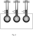
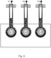
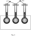
- Figs. 2-9 relate to the new system for monitoring a thermosyphon of a medium voltage switchgear, new systems for monitoring three thermosyphons of a medium voltage switchgear, new method for monitoring a thermosyphon of a medium voltage switchgear, and new methods for monitoring three thermosyphons of a medium voltage switchgear.
- thermosyphon of a medium voltage switchgear
- the thermosyphon comprises an evaporator section 4 an adiabatic section 5 and a condenser section 6.
- the evaporator section is in thermal contact with a conductor L1, L2, L3, 3 of the switchgear.
- the adiabatic section links the evaporator section to the condenser section.
- at least some of a working fluid in the thermosyphon is evaporated to a vapor phase 7b in the evaporator section and flows via the adiabatic section to the condenser section and is condensed in the condenser section to a liquid phase 7a and returns via the adiabatic section to the evaporator section.
- the system for monitoring the thermosyphon comprises:
- the determination that the thermosyphon has a fault comprises a comparison of the temperature data with at least one reference temperature and/or a comparison of the pressure data with at least one reference pressure.
- the determination that the thermosyphon has a fault comprises a determination that the temperature data is different to the at least one reference temperature by a threshold temperature and/or a determination that the pressure data is different to the at least one reference pressure by a threshold pressure.
- thermosyphon has a fault.
- Reference temperature and pressure data can be acquired for a thermosyphon that is known to be operating correctly with no fault, and then data acquired for that thermosyphon or an equivalent thermosyphon can be compared with this reference data to assess if the thermosyphon has a fault.
- thermosyphons of a medium voltage switchgear comprising an evaporator section 4 an adiabatic section 5 and a condenser section 6.
- Each evaporator section is in thermal contact with a different one or three conductors L1, L2, L3, 3 of the switchgear.
- the adiabatic section of each thermosyphon links the evaporator section of each thermosyphon to the condenser section of each thermosyphon.
- thermosyphon In use at least some of a working fluid in each thermosyphon is evaporated to a vapor phase 7b in the evaporator section and flows via the adiabatic section to the condenser section and is condensed in the condenser section to a liquid phase 7a and returns via the adiabatic section to the evaporator section.
- the system for monitoring the three thermosyphons comprises:
- the three conductors L1, L2, L3, 3 of the switchgear are identical.
- each one the three conductors L1, L2, L3, 3 of the switchgear are associated with a different phase of a three phase system.
- the three conductors L1, L2, L3, 3 of the switchgear are anticipated to carry equivalent currents to each other.
- the three conductors L1, L2, L3, 3 of the switchgear are anticipated to have equivalent temperatures to each other if not being cooled or if being cooled by the thermosyphons that do not have faults.
- the determination that the first thermosyphon has a fault comprises a comparison of the first temperature data with at least one reference temperature and/or a comparison of the first pressure data with at least one reference pressure.
- the determination that the first thermosyphon has a fault comprises a determination that the first temperature data is different to the at least one reference temperature by a threshold temperature and/or a determination that the first pressure data is different to the at least one reference pressure by a threshold pressure
- the determination that the second thermosyphon has a fault comprises a comparison of the second temperature data with at least one reference temperature and/or a comparison of the second pressure data with at least one reference pressure.
- the determination that the second thermosyphon has a fault comprises a determination that the second temperature data is different to the at least one reference temperature by a threshold temperature and/or a determination that the second pressure data is different to the at least one reference pressure by a threshold pressure
- the determination that the third thermosyphon has a fault comprises a comparison of the third temperature data with at least one reference temperature and/or a comparison of the third pressure data with at least one reference pressure.
- the determination that the third thermosyphon has a fault comprises a determination that the third temperature data is different to the at least one reference temperature by a threshold temperature and/or a determination that the third pressure data is different to the at least one reference pressure by a threshold pressure.
- thermosyphons whether liquid or vapor, is for example greater than it should be, which could involve it being greater than a threshold of what it should be, an alarm can be signalled that the thermosyphon has a fault.
- Reference temperature and pressure data can be acquired for the thermosyphons that are known to be operating correctly with no fault, and then data acquired for these thermosyphon or equivalent thermosyphons can be compared with this reference data to assess if any thermosyphon has a fault.
- the determination that the first thermosyphon has a fault comprises a comparison of the first temperature data with the second temperature data and/or a comparison of the first pressure data with the second pressure data.
- the determination that the first thermosyphon has a fault comprises a determination that the first temperature data is different to the second temperature by a threshold temperature and/or a determination that the first pressure data is different to the second pressure by a threshold pressure.
- the determination that the first thermosyphon has a fault comprises a comparison of the first temperature data with the third temperature data and/or a comparison of the first pressure data with the third pressure data.
- the determination that the first thermosyphon has a fault comprises a determination that the first temperature data is different to the third temperature by a threshold temperature and/or a determination that the first pressure data is different to the third pressure by a threshold pressure.
- the determination that the first thermosyphon has a fault comprises a determination that the first temperature data is different to the second temperature by a threshold temperature and/or a determination that the first pressure data is different to the second pressure by a threshold pressure, and a determination that the first temperature data is different to the third temperature by the threshold temperature and/or a determination that the first pressure data is different to the third pressure by the threshold pressure.
- the determination that the first thermosyphon has a fault comprises a determination that the second temperature data is different to the third temperature by an amount less than the threshold temperature and/or a determination that the second pressure data is different to the third pressure by an amount less than the threshold pressure.
- first temperature data and/or pressure data are greater than the second temperature data and/or second pressure data, by for example threshold magnitudes, it can be determined that the determined that the first thermosyphon has a fault.
- the first temperature data and/or the first pressure data can also be greater than reference values as well as being greater than corresponding values for another thermosyphon that provides a greater confidence that there is a fault ibn the first thermosyphon.
- the first temperature data and/or first pressure data can also be greater than the corresponding values for the third thermosyphon as well as for the second thermosyphon that again gives increased confidence that the first thermosyphon has a fault. This is especially the case if the absolute temperature value and/or absolute pressure for the first thermosyphon is/are outside of the expected range values, whilst at the same time the values for the second and third thermosyphons are within the expected ranges.
- the determination that the second thermosyphon has a fault comprises a comparison of the second temperature data with the first temperature data and/or a comparison of the second pressure data with the first pressure data.
- the determination that the second thermosyphon has a fault comprises a determination that the second temperature data is different to the first temperature by a threshold temperature and/or a determination that the second pressure data is different to the first pressure by a threshold pressure.
- the determination that the second thermosyphon has a fault comprises a comparison of the second temperature data with the third temperature data and/or a comparison of the second pressure data with the third pressure data.
- the determination that the second thermosyphon has a fault comprises a determination that the second temperature data is different to the third temperature by a threshold temperature and/or a determination that the second pressure data is different to the third pressure by a threshold pressure.
- the determination that the second thermosyphon has a fault comprises a determination that the second temperature data is different to the first temperature by a threshold temperature and/or a determination that the second pressure data is different to the first pressure by a threshold pressure, and a determination that the second temperature data is different to the third temperature by the threshold temperature and/or a determination that the second pressure data is different to the third pressure by the threshold pressure.
- the determination that the second thermosyphon has a fault comprises a determination that the first temperature data is different to the third temperature by an amount less than the threshold temperature and/or a determination that the first pressure data is different to the third pressure by an amount less than the threshold pressure.
- the determination that the third thermosyphon has a fault comprises a comparison of the third temperature data with the first temperature data and/or a comparison of the third pressure data with the first pressure data.
- the determination that the third thermosyphon has a fault comprises a determination that the third temperature data is different to the first temperature by a threshold temperature and/or a determination that the third pressure data is different to the first pressure by a threshold pressure.
- the determination that the third thermosyphon has a fault comprises a comparison of the third temperature data with the second temperature data and/or a comparison of the third pressure data with the second pressure data.
- the determination that the third thermosyphon has a fault comprises a determination that the third temperature data is different to the second temperature by a threshold temperature and/or a determination that the third pressure data is different to the second pressure by a threshold pressure.
- the determination that the third thermosyphon has a fault comprises a determination that the third temperature data is different to the first temperature by a threshold temperature and/or a determination that the third pressure data is different to the first pressure by a threshold pressure, and a determination that the third temperature data is different to the second temperature by the threshold temperature and/or a determination that the third pressure data is different to the second pressure by the threshold pressure.
- the determination that the third thermosyphon has a fault comprises a determination that the first temperature data is different to the second temperature by an amount less than the threshold temperature and/or a determination that the first pressure data is different to the second pressure by an amount less than the threshold pressure.
- thermosyphon comprising an evaporator section 4 an adiabatic section 5 and a condenser section 6.
- Each evaporator section is in thermal contact with a different one or three conductors L1, L2, L3, 3 of the switchgear.
- the adiabatic section of each thermosyphon links the evaporator section of each thermosyphon to the condenser section of each thermosyphon.
- thermosyphon In use at least some of a working fluid in each thermosyphon is evaporated to a vapor phase 7b in the evaporator section and flows via the adiabatic section to the condenser section and is condensed in the condenser section to a liquid phase 7a and returns via the adiabatic section to the evaporator section.
- the system for monitoring the three thermosyphons comprises:
- the three conductors L1, L2, L3, 3 of the switchgear are identical.
- each one the three conductors L1, L2, L3, 3 of the switchgear are associated with a different phase of a three phase system.
- the three conductors L1, L2, L3, 3 of the switchgear are anticipated to carry equivalent currents to each other.
- the three conductors L1, L2, L3, 3 of the switchgear are anticipated to have equivalent temperatures to each other if not being cooled or if being cooled by the thermosyphons that do not have faults.
- the processing unit is configured to determine that the first thermosyphon has a fault when the pressure of the working fluid in the first thermosyphon is greater than the pressure of the working fluid in the second thermosyphon by more than a threshold value.
- the processing unit is configured to determine that the first thermosyphon has a fault when the pressure of the working fluid in the second thermosyphon is not greater than the pressure of the working fluid in the third thermosyphon by more than a threshold value.
- the processing unit is configured to determine that the first thermosyphon has a fault when the pressure of the working fluid in the first thermosyphon is greater than the pressure of the working fluid in the second thermosyphon by more than a threshold value, and the pressure of the working fluid in the second thermosyphon is not greater than the pressure of the working fluid in the third thermosyphon by more than the threshold value.
- the processing unit is configured to determine that the third thermosyphon has a fault when the pressure of the working fluid in the third thermosyphon is greater than the pressure of the working fluid in the second thermosyphon by more than a threshold value.
- the processing unit is configured to determine that the third thermosyphon has a fault when the pressure of the working fluid in the second thermosyphon is not greater than the pressure of the working fluid in the first thermosyphon by more than a threshold value.
- the processing unit is configured to determine that the third thermosyphon has a fault when the pressure of the working fluid in the third thermosyphon is greater than the pressure of the working fluid in the second thermosyphon by more than a threshold value, and the pressure of the working fluid in the second thermosyphon is not greater than the pressure of the working fluid in the first thermosyphon by more than a threshold value.
- the processing unit is configured to determine that the second thermosyphon has a fault when the pressure of the working fluid in the second thermosyphon is greater than the pressure of the working fluid in the first thermosyphon by more than a threshold value, and the pressure of the working fluid in the second thermosyphon is greater than the pressure of the working fluid in the third thermosyphon by more than the threshold value.
- the processing unit is configured to determine that the second thermosyphon has a fault when the pressure of the working fluid in the second thermosyphon is greater than the pressure of the working fluid in the first thermosyphon by more than a threshold value, and the pressure of the working fluid in the second thermosyphon is greater than the pressure of the working fluid in the third thermosyphon by more than the threshold value.
- the processing unit is configured to determine that the second thermosyphon has a fault when a magnitude of the differential pressure between the pressure of the working fluid in the second thermosyphon and the pressure of the working fluid in the first thermosyphon is within a threshold value of a magnitude of the differential pressure between the pressure of the working fluid in the second thermosyphon and the pressure of the working fluid in the third thermosyphon.
- a switchgear can have one of the monitoring systems as described above.
- thermosyphon comprises an evaporator section 4 an adiabatic section 5 and a condenser section 6.
- the evaporator section is in thermal contact with a conductor L1, L2, L3, 3 of the switchgear.
- the adiabatic section links the evaporator section to the condenser section.
- at least some of a working fluid in the thermosyphon is evaporated to a vapor phase 7b in the evaporator section and flows via the adiabatic section to the condenser section and is condensed in the condenser section to a liquid phase 7a and returns via the adiabatic section to the evaporator section.
- the method for monitoring the thermosyphon comprises:
- the determining that the thermosyphon has a fault comprises comparing the temperature data with at least one reference temperature and/or comparing the pressure data with at least one reference pressure.
- the determining that the thermosyphon has a fault comprises determining that the temperature data is different to the at least one reference temperature by a threshold temperature and/or determining that the pressure data is different to the at least one reference pressure by a threshold pressure.
- thermosyphon comprises an evaporator section 4 an adiabatic section 5 and a condenser section 6.
- Each evaporator section is in thermal contact with a different one or three conductors L1, L2, L3, 3 of the switchgear.
- the adiabatic section of each thermosyphon links the evaporator section of each thermosyphon to the condenser section of each thermosyphon.
- thermosyphon In use at least some of a working fluid in each thermosyphon is evaporated to a vapor phase 7b in the evaporator section and flows via the adiabatic section to the condenser section and is condensed in the condenser section to a liquid phase 7a and returns via the adiabatic section to the evaporator section.
- the method for monitoring the three thermosyphons comprises:
- the three conductors L1, L2, L3, 3 of the switchgear are identical.
- each one the three conductors L1, L2, L3, 3 of the switchgear are associated with a different phase of a three phase system.
- the three conductors L1, L2, L3, 3 of the switchgear are anticipated to carry equivalent currents to each other.
- the three conductors L1, L2, L3, 3 of the switchgear are anticipated to have equivalent temperatures to each other if not being cooled or if being cooled by the thermosyphons that do not have faults.
- the determining that the first thermosyphon has a fault comprises comparing the first temperature data with at least one reference temperature and/or comparing the first pressure data with at least one reference pressure.
- the determining that the first thermosyphon has a fault comprises determining that the first temperature data is different to the at least one reference temperature by a threshold temperature and/or determining that the first pressure data is different to the at least one reference pressure by a threshold pressure
- the determining that the second thermosyphon has a fault comprises comparing the second temperature data with at least one reference temperature and/or comparing the second pressure data with at least one reference pressure.
- the determining that the second thermosyphon has a fault comprises determining that the second temperature data is different to the at least one reference temperature by a threshold temperature and/or determining that the second pressure data is different to the at least one reference pressure by a threshold pressure
- the determination that the third thermosyphon has a fault comprises comparing the third temperature data with at least one reference temperature and/or comparing the third pressure data with at least one reference pressure.
- the determining that the third thermosyphon has a fault comprises determining that the third temperature data is different to the at least one reference temperature by a threshold temperature and/or determining that the third pressure data is different to the at least one reference pressure by a threshold pressure.
- the determination that the first thermosyphon has a fault comprises comparing the first temperature data with the second temperature data and/or comparing the first pressure data with the second pressure data.
- the determining that the first thermosyphon has a fault comprises a determining that the first temperature data is different to the second temperature by a threshold temperature and/or determining that the first pressure data is different to the second pressure by a threshold pressure.
- the determining that the first thermosyphon has a fault comprises comparing the first temperature data with the third temperature data and/or comparing the first pressure data with the third pressure data.
- the determining that the first thermosyphon has a fault comprises determining that the first temperature data is different to the third temperature by a threshold temperature and/or determining that the first pressure data is different to the third pressure by a threshold pressure.
- the determining that the second thermosyphon has a fault comprises comparing the second temperature data with the first temperature data and/or comparing the second pressure data with the first pressure data.
- the determining that the second thermosyphon has a fault comprises determining that the second temperature data is different to the first temperature by a threshold temperature and/or determining that the second pressure data is different to the first pressure by a threshold pressure.
- the determining that the second thermosyphon has a fault comprises comparing the second temperature data with the third temperature data and/or comparing the second pressure data with the third pressure data.
- the determining that the second thermosyphon has a fault comprises determining that the second temperature data is different to the third temperature by a threshold temperature and/or determining that the second pressure data is different to the third pressure by a threshold pressure.
- the determining that the third thermosyphon has a fault comprises comparing the third temperature data with the first temperature data and/or comparing the third pressure data with the first pressure data.
- the determining that the third thermosyphon has a fault comprises determining that the third temperature data is different to the first temperature by a threshold temperature and/or determining that the third pressure data is different to the first pressure by a threshold pressure.
- the determination that the third thermosyphon has a fault comprises comparing the third temperature data with the second temperature data and/or comparing the third pressure data with the second pressure data.
- the determining that the third thermosyphon has a fault comprises determining that the third temperature data is different to the second temperature by a threshold temperature and/or determining that the third pressure data is different to the second pressure by a threshold pressure.
- thermosyphon comprising an evaporator section 4, an adiabatic section 5 and a condenser section 6.
- Each evaporator section is in thermal contact with a different one or three conductors L1, L2, L3, 3 of the switchgear.
- the adiabatic section of each thermosyphon links the evaporator section of each thermosyphon to the condenser section of each thermosyphon.
- thermosyphon In use at least some of a working fluid in each thermosyphon is evaporated to a vapor phase 7b in the evaporator section and flows via the adiabatic section to the condenser section and is condensed in the condenser section to a liquid phase 7a and returns via the adiabatic section to the evaporator section.
- the method for monitoring the three thermosyphons comprises:
- the three conductors L1, L2, L3, 3 of the switchgear are identical.
- each one the three conductors L1, L2, L3, 3 of the switchgear are associated with a different phase of a three phase system.
- the three conductors L1, L2, L3, 3 of the switchgear are anticipated to carry equivalent currents to each other.
- the three conductors L1, L2, L3, 3 of the switchgear are anticipated to have equivalent temperatures to each other if not being cooled or if being cooled by the thermosyphons that do not have faults.
- the method comprises determining by processing unit that the first thermosyphon has a fault when the pressure of the working fluid in the first thermosyphon is greater than the pressure of the working fluid in the second thermosyphon by more than a threshold value.
- the method comprises determining by processing unit that the first thermosyphon has a fault when the pressure of the working fluid in the second thermosyphon is not greater than the pressure of the working fluid in the third thermosyphon by more than a threshold value.
- the method comprises determining by the processing unit that the first thermosyphon has a fault when the pressure of the working fluid in the first thermosyphon is greater than the pressure of the working fluid in the second thermosyphon by more than a threshold value, and the pressure of the working fluid in the second thermosyphon is not greater than the pressure of the working fluid in the third thermosyphon by more than the threshold value.
- the method comprises determining by the processing unit that the third thermosyphon has a fault when the pressure of the working fluid in the third thermosyphon is greater than the pressure of the working fluid in the second thermosyphon by more than a threshold value.
- the method comprises determining by the processing unit that the third thermosyphon has a fault when the pressure of the working fluid in the second thermosyphon is not greater than the pressure of the working fluid in the first thermosyphon by more than a threshold value.
- the method comprises determining by the processing unit that the third thermosyphon has a fault when the pressure of the working fluid in the third thermosyphon is greater than the pressure of the working fluid in the second thermosyphon by more than a threshold value, and the pressure of the working fluid in the second thermosyphon is not greater than the pressure of the working fluid in the first thermosyphon by more than a threshold value.
- the method comprises determining by the processing unit that the second thermosyphon has a fault when the pressure of the working fluid in the second thermosyphon is greater than the pressure of the working fluid in the first thermosyphon by more than a threshold value, and the pressure of the working fluid in the second thermosyphon is greater than the pressure of the working fluid in the third thermosyphon by more than the threshold value.
- the method comprises determining by the processing unit that the second thermosyphon has a fault when the pressure of the working fluid in the second thermosyphon is greater than the pressure of the working fluid in the first thermosyphon by more than a threshold value, and the pressure of the working fluid in the second thermosyphon is greater than the pressure of the working fluid in the third thermosyphon by more than the threshold value.
- the method comprises determining by the processing unit that the second thermosyphon has a fault when a magnitude of the differential pressure between the pressure of the working fluid in the second thermosyphon and the pressure of the working fluid in the first thermosyphon is within a threshold value of a magnitude of the differential pressure between the pressure of the working fluid in the second thermosyphon and the pressure of the working fluid in the third thermosyphon
- thermosyphon of a medium voltage switchgear new systems for monitoring three thermosyphons of a medium voltage switchgear, new method for monitoring a thermosyphon of a medium voltage switchgear, and new methods for monitoring three thermosyphons of a medium voltage switchgear are now described in specific detail where reference is again made to Figs. 2-9 .
- thermosyphon monitoring algorithms In effect two different techniques, or thermosyphon monitoring algorithms, have been developed based on the assessment of either temperatures or the pressures of the saturated working fluid in three thermosyphons simultaneously, and evaluating the differences in either temperature or pressure between neighboring thermosyphons. It is to be noted that temperature monitoring can be carried out alone or pressure monitoring can be carried out alone, however both temperature and pressure monitoring can be both be carried out simultaneously.
- the first condition which should trigger an alarm, is when the value of either the absolute temperature or the absolute pressure exceeds a limit for any of the three thermosyphons.
- the second condition which should trigger an alarm, is when the fluid temperature difference or the fluid pressure difference between any two thermosyphons exceeds a limit.
- the second condition relies on the fact that it is extremely unlikely that all three thermosyphons develop the same failure simultaneously. Therefore, the fluid saturation temperature of the failed thermosiphon would deviate from the fluid saturation temperatures of normally functioning or less failed thermosyphons.
- thermosyphon is equipped with a temperature sensor T1, T2, T3.
- the sensors are in good thermal contact with the adiabatic section of the corresponding thermosyphon, but can be applied to the evaporator section or to the condenser section.
- a protection and control relay (not shown), also termed a processing unit, collects temperature readings and generates an alarm, if one of two criteria is satisfied:
- thermosyphon is equipped with a gas absolute pressure sensor (P1, P2, P3).
- the sensors are able to measure the pressure of the gas phase of the working fluid, but sensor can also be used to measure the pressure of the liquid phase.
- a protection and control relay (not shown), also termed a processing unit, collects pressure readings and generates an alarm, if one of two criteria is satisfied:
- T M , ⁇ T M , P M , and ⁇ P M can be defined for specific implementations of switchgear compartments and thermosyphon designs, and in agreement with the corresponding standards and norms.
- the values mentioned above are just an example, and other values can be utilized.
- thermosyphons designed for the circuit breaker compartment of a MV GIS.
- 3M TM Novec 649 Engineered Fluid perfluroketone C 6 F 12 O
- Clamp-on temperature monitoring sensors of type Pt100 were attached to the tubes connecting the evaporator and the condenser.
- the fluid vapor pressure in each thermosyphon (P 1 , P 2 and P 3 ) was measured by manometers installed at the top of the condensers.
- the evaporators were heated up to about 158 W per thermosyphon.
- the monitoring was done with the ABB protection and control relay REX640.
- thermosyphon failure modes were generated experimentally in the lab on the set of three thermosyphons. The test results demonstrated that all simulated failure modes would trigger alarm, both in case of the temperature-based and the pressure-based monitoring.
- the acceptable alarm level values are:
- thermosyphons The following provides details on how the new monitoring systems can detect faults in thermosyphons.
- the test setup consists of three thermosyphons designed for the circuit breaker compartment, one thermosyphon per phase L1, L2, L3.
- Thermocouples were also used to measure the temperature of the condensers (Tc1, Tc2 , and Tc3) and evaporators (Te1, Te2 , and Te3).
- the fluid vapor pressure in each thermosyphon (P1, P2 and P3) was measured by manometers installed at the top of the condensers.
- the evaporators were heated up to about 158 W per TS by cartridge heaters installed into cylindric holes drilled in the center of the aluminum pole parts. The cartridges with almost equal resistances were electrically connected in parallel.
- Temperature readings from the Pt100 sensors were collected by a relay.
- the alarms were programmed to be activated as soon as either one of the sensor temperatures exceeded the limit TM, or any ⁇ Tij exceeded the limit ⁇ TM.
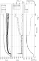
- Fig. 5 shows the detection of a fault relating to an increase of the fluid pressure due to the non-condensable gas (NCG, mostly air) penetrating the thermosyphon, where in the situation of penetration of air or any other non-condensable gas (NCG) into a thermosyphon during operation, NCG would accumulate at the top of the condenser chamber.
- NCG non-condensable gas
- the top graph of Fig. 5 shows temperature data, where the top curve is Te1, with Te2 and Te3 just below this curve, and where Te1 deviates upwards from Te2 and Te3 due to the air penetration.
- the middle three curves are T1, T2 and T3, where again T1 deviates upwards due to the air penetration.
- the bottom curves are Tc1, Tc2, and Tc3, where Tc 1 deviates downwards due to air penetration.
- the middle graph of Fig. 5 shows differential temperature and differential pressure curves. Although 8 curves are labeled, only 5 curves are visible because dT12 is the same as dT21, dt13 is the same as dT31 and dT23 is the same as dT32.
- the generally flat curve at the bottom is dT32 and the generally flat curve in the middle is dP23.
- the top curve that rises is dP12, and the other two curves that rise are dT12 and dT13.
- the bottom graph of Fig. 5 shows pressure data and heat load.
- the top flat curve is the heat load, and the curve that deviates upwards is P1, with P2 and P3 following each other.
- absolute temperature values, and absolute pressure values can be used to determine if there is a fault, where the other data shown for the other two heats pipes could be reference data. However, also by monitoring all three thermosyphons differential temperature and differential pressure data can be used to determine that this fault has occurred.
- Fig 6 shows the detection of a fault relating to fluid escaping the thermosyphon slowly from the lower part of the thermosyphon (from the evaporator).
- This test simulates the failure mode of one thermosyphon developing a leak in the evaporator area.
- the pressure P1 started decreasing and then the evaporator temperature Te1 started increasing while the monitoring sensor temperature T1 was decreasing. Power was turned off at about 450 minutes leading to a change in signal levels.
- the top graph of Fig. 6 shows temperature data, where the top curve is Te1, with Te2 and Te3 just below this curve, and where Te1 deviates upwards from Te2 and Te3 due to the leak.
- the middle three curves are T1, T2 and T3, where T1 deviates downwards due to the leak.
- the bottom curves are Tc1, Tc2, and Tc3, where Tc 1 deviates downwards due to the leak.
- the middle graph of Fig. 6 shows differential temperature and differential pressure curves. Although 8 curves are labeled, only 5 curves are visible because dT12 is the same as dT21, dT13 is the same as dT31 and dT23 is the same as dT32.
- the generally flat curve at the bottom is dT32 and the generally flat curve in the middle is dP23.
- the top curve that rises is dP12, and the other two curves that rise are dT12 and dT13.
- the bottom graph of Fig. 6 shows pressure data and heat load.
- the top flat curve is the heat load, that fall at 450 minutes when the power is switched off.
- the curve that deviates downward is P1, with P2 and P3 following each other.
- absolute temperature values, and absolute pressure values can be used to determine if there is a fault, where the other data shown for the other two heats pipes could be reference data. However, also by monitoring all three thermosyphons differential temperature and differential pressure data can be used to determine that this fault has occurred.
- Fig 7 shows the detection of a fault relating to fluid with NCG escaping the thermosyphon from the upper part of the thermosyphon.
- the case when a leak develops at the top of a thermosyphon, is different from the case of a leak at the bottom described above.
- NCG escapes the thermosyphon together with the working fluid.
- This failure was simulated by a small opening of the charging valve at the condenser top during steady operation.
- t 100 min the charging valve of thermosyphon L1 was opened slightly.
- pressure P1 and monitoring temperature T1 started decreasing.
- the cooling performance of TS L1 actually improved temporarily, until most of the fluid had escaped from thermosyphon L1 at t ⁇ 185 min.
- the top graph of Fig. 7 shows temperature data, where the top curve that deviates downwards is Te1, with Te2 and Te3 continuing together, and where Te1 deviates downwards from Te2 and Te3 due to the leak.
- the middle three curves are T1, T2 and T3, where T1 deviates downwards due to the leak.
- the bottom curves are Tc1, Tc2, and Tc3, where Tc 1 deviates downwards due to the leak.
- the middle graph of Fig. 7 shows differential temperature and differential pressure curves. Although 8 curves are labeled, only 5 curves are visible because dT12 is the same as dT21, dT13 is the same as dT31 and dT23 is the same as dT32.
- the generally flat curve at the bottom is dT32 and the generally flat curve in the middle is dP23.
- the top curve that rises is dP12, and the other two curves that rise are dT12 and dT13.
- the bottom graph of Fig. 7 shows pressure data and heat load.
- the top flat curve is the heat load.
- the curve that deviates downward is P1, with P2 and P3 following each other.
- absolute temperature values, and absolute pressure values can be used to determine if there is a fault, where the other data shown for the other two heats pipes could be reference data. However, also by monitoring all three thermosyphons differential temperature and differential pressure data can be used to determine that this fault has occurred.
- Fig 8 shows the detection of a fault relating to significant damage to a thermosyphon for example during transportation and commissioning, such that a thermosyphon connection is not completely tight.
- This failure mode was simulated by first fully opening the valve of TS L1 and then applying a heat load.
- the pressure in the damaged thermosyphon L1 is equal to the ambient pressure, and the monitoring system can easily recognize this failure soon after the pressure in thermosyphons L2 and L3 becomes significantly higher than the ambient pressure, and also that ⁇ T 12 and ⁇ T 13 would exceed ⁇ TM.
- the top graph of Fig. 8 shows temperature data, where the top curve that deviates upwards is Te1, with Te2 and Te3 following each other and end up lower than Te1.
- the middle three curves are T1, T2 and T3, where T1 is the lowest curve.
- the bottom curves are Tc1, Tc2, and Tc3, where Tc1 starts with the higher temperature and ends with the lowest temperature.
- the middle graph of Fig. 8 shows differential temperature and differential pressure curves. Although 8 curves are labeled, only 5 curves are visible because dT12 is the same as dT21, dT13 is the same as dT31 and dT23 is the same as dT32.
- the generally flat curve at the bottom is dT32 and the generally flat curve in the middle is dP23.
- the top curve is dP12, and the other two curves that rise are dT12 and dT13.
- the bottom graph of Fig. 8 shows pressure data and heat load.
- the top flat curve is the heat load.
- the curve that is relatively constant is P1, with P2 and P3 following each other and rising gradually to a plateau.
- absolute temperature values, and absolute pressure values can be used to determine if there is a fault, where the other data shown for the other two heats pipes could be reference data. However, also by monitoring all three thermosyphons differential temperature and differential pressure data can be used to determine that this fault has occurred.
- Fig 9 shows the detection of a fault relating to a reduction in convection cooling of a thermosyphon condenser, for example if a heat sink at the condenser become partially blocked.
- the heat sink at the condenser was partially blocked at time 200 minutes and then further blocked at time 275 minutes.
- blockage, and indeed with increased blockage, of the surface of heat sink of condenser L1 the temperature and the pressure of the fluid in L1 increases. This is accurately reflected in the readings of T1 monitoring sensor as well as in ⁇ T 12 and ⁇ T 13 values.
- the pressure difference ⁇ P 12 also increased due to the failure and exceeded ⁇ P 12 > 0.4 bar
- the top graph of Fig. 9 shows temperature data, where the top curve is Te1, with Te2 and Te3 just below this curve, and where Te1 deviates upwards from Te2 and Te3 due to the reduction in convection cooling.
- the middle three curves are T1, T2 and T3, where T1 deviates upwards due to the reduction in convection cooling.
- the bottom curves are Tc1, Tc2, and Tc3, where Tc 1 deviates upwards due to the reduction in convection cooling.
- the middle graph of Fig. 9 shows differential temperature and differential pressure curves. Although 8 curves are labeled, only 5 curves are visible because dT12 is the same as dT21, dT13 is the same as dT31 and dT23 is the same as dT32.
- the generally flat curve at the bottom is dT32 and the generally flat curve in the middle is dP23.
- the top curve that rises is dP12, and the other two curves that rise are dT12 and dT13.
- the bottom graph of Fig. 9 shows pressure data and heat load.
- the top flat curve is the heat load.
- the curve that deviates upwards is P1, with P2 and P3 following each other.
- absolute temperature values, and absolute pressure values can be used to determine if there is a fault, where the other data shown for the other two heats pipes could be reference data. However, also by monitoring all three thermosyphons differential temperature and differential pressure data can be used to determine that this fault has occurred.
- thermosyphons of a medium voltage switchgear can detect a number of different faults that can occur for a thermosyphon.
- a computer program or computer program element is provided that is characterized by being configured to execute the method steps of any of the methods according to one of the preceding embodiments, on an appropriate apparatus or system.
- the computer program element might therefore be stored on a computer unit, which might also be part of an embodiment.
- This computing unit may be configured to perform or induce performing of the steps of the method described above. Moreover, it may be configured to operate the components of the above-described system.
- the computing unit can be configured to operate automatically and/or to execute the orders of a user.
- a computer program may be loaded into a working memory of a data processor.
- the data processor may thus be equipped to carry out the method according to one of the preceding embodiments.
- This exemplary embodiment of the invention covers both, a computer program that right from the beginning uses the invention and computer program that by means of an update turns an existing program into a program that uses the invention.
- the computer program element might be able to provide all necessary steps to fulfill the procedure of an exemplary embodiment of the method as described above.
- a computer readable medium such as a CD-ROM, USB stick or the like
- the computer readable medium has a computer program element stored on it which computer program element is described by the preceding section.
- a computer program may be stored and/or distributed on a suitable medium, such as an optical storage medium or a solid state medium supplied together with or as part of other hardware, but may also be distributed in other forms, such as via the internet or other wired or wireless telecommunication systems.
- a suitable medium such as an optical storage medium or a solid state medium supplied together with or as part of other hardware, but may also be distributed in other forms, such as via the internet or other wired or wireless telecommunication systems.
- the computer program may also be presented over a network like the World Wide Web and can be downloaded into the working memory of a data processor from such a network.
- a medium for making a computer program element available for downloading is provided, which computer program element is arranged to perform a method according to one of the previously described embodiments of the invention.
Landscapes
- Engineering & Computer Science (AREA)
- Physics & Mathematics (AREA)
- Life Sciences & Earth Sciences (AREA)
- Sustainable Development (AREA)
- Thermal Sciences (AREA)
- Mechanical Engineering (AREA)
- General Engineering & Computer Science (AREA)
- General Physics & Mathematics (AREA)
- Power Engineering (AREA)
- Measuring Fluid Pressure (AREA)
Priority Applications (1)
| Application Number | Priority Date | Filing Date | Title |
|---|---|---|---|
| EP23151971.1A EP4404402A1 (de) | 2023-01-17 | 2023-01-17 | System zur überwachung eines thermosyphons einer mittelspannungsschaltanlage |
Applications Claiming Priority (1)
| Application Number | Priority Date | Filing Date | Title |
|---|---|---|---|
| EP23151971.1A EP4404402A1 (de) | 2023-01-17 | 2023-01-17 | System zur überwachung eines thermosyphons einer mittelspannungsschaltanlage |
Publications (1)
| Publication Number | Publication Date |
|---|---|
| EP4404402A1 true EP4404402A1 (de) | 2024-07-24 |
Family
ID=84982180
Family Applications (1)
| Application Number | Title | Priority Date | Filing Date |
|---|---|---|---|
| EP23151971.1A Withdrawn EP4404402A1 (de) | 2023-01-17 | 2023-01-17 | System zur überwachung eines thermosyphons einer mittelspannungsschaltanlage |
Country Status (1)
| Country | Link |
|---|---|
| EP (1) | EP4404402A1 (de) |
Citations (4)
| Publication number | Priority date | Publication date | Assignee | Title |
|---|---|---|---|---|
| EP1667300A1 (de) * | 2004-12-03 | 2006-06-07 | Abb Research Ltd. | Hochspannungsanlage und Hochleistungsschalter mit Kühlung |
| US7771114B2 (en) * | 2005-06-23 | 2010-08-10 | Abb Research Ltd | Electrical installation with a cooling element and method for operating said installation |
| EP3171469A1 (de) * | 2015-11-19 | 2017-05-24 | ABB Schweiz AG | Verfahren zur detektion loser verbindungen in mittelspannungsschaltanlagen und die mittelspannungsschaltanlage selbst |
| EP4084244A1 (de) * | 2021-04-28 | 2022-11-02 | ABB Schweiz AG | Kühlvorrichtung für eine mittelspannungsschaltanlage |
-
2023
- 2023-01-17 EP EP23151971.1A patent/EP4404402A1/de not_active Withdrawn
Patent Citations (4)
| Publication number | Priority date | Publication date | Assignee | Title |
|---|---|---|---|---|
| EP1667300A1 (de) * | 2004-12-03 | 2006-06-07 | Abb Research Ltd. | Hochspannungsanlage und Hochleistungsschalter mit Kühlung |
| US7771114B2 (en) * | 2005-06-23 | 2010-08-10 | Abb Research Ltd | Electrical installation with a cooling element and method for operating said installation |
| EP3171469A1 (de) * | 2015-11-19 | 2017-05-24 | ABB Schweiz AG | Verfahren zur detektion loser verbindungen in mittelspannungsschaltanlagen und die mittelspannungsschaltanlage selbst |
| EP4084244A1 (de) * | 2021-04-28 | 2022-11-02 | ABB Schweiz AG | Kühlvorrichtung für eine mittelspannungsschaltanlage |
Similar Documents
| Publication | Publication Date | Title |
|---|---|---|
| US20220359946A1 (en) | Battery module gas sensor for battery cell monitoring | |
| Baraya et al. | Heat pipe dryout and temperature hysteresis in response to transient heat pulses exceeding the capillary limit | |
| RU2449397C1 (ru) | Способ и устройство для определения относительной влажности электрического устройства, заполненного изолирующей жидкостью | |
| EP3299783B1 (de) | Thermische überwachung einer leistungsvorrichtung | |
| CA3044692C (en) | Method for the in-situ calibration of a thermometer | |
| JP4847522B2 (ja) | 冷却要素を備えた電気設備及びこの設備を運転するための方法 | |
| BR0010695B1 (pt) | aparelho e método de detecção de status para equipamento elétrico enchido com fluido. | |
| TWI784962B (zh) | 用於在溫度調節的儲存裝置內使用的熱虹吸管及溫度調節的儲存裝置 | |
| TW201717696A (zh) | 用於增強加熱器使用壽命和性能的整合裝置及方法 | |
| WO2013073358A1 (ja) | 水位温度測定装置 | |
| CN116034243A (zh) | 制冷系统泄漏检测 | |
| CN109490355A (zh) | 一种导热系数测试装置及测量导热系数的方法 | |
| US7473868B2 (en) | Fail safe HVAC temperature and medium presence sensor | |
| KR20120002926A (ko) | 냉각 시스템의 기능 모니터링 및/또는 제어 방법, 및 대응하는 냉각 시스템 | |
| CN115704713B (zh) | 用于监测设备的系统 | |
| Baraya et al. | Wetting hysteresis as the mechanism of heat pipe post-dryout thermal hysteresis and recovery | |
| AU2021226571A1 (en) | Testing methods and apparatuses using simulated servers | |
| CN115615553B (zh) | 用于监测设备的系统 | |
| Sologubenko et al. | Wall damage of cylindrical heat pipes caused by water freezing | |
| Williams et al. | A device and technique to measure the heat transfer limit of a planar heat pipe wick | |
| Hainey et al. | Digital Shadow-Based Detection of Blockage Formation in Water-Cooled Power Electronics | |
| US11785747B2 (en) | Methods and devices for testing immersion cooling controllers | |
| US20100301208A1 (en) | Mass Spectrometer | |
| Penzel et al. | Calibration parameter drift compensation of metal resistive bolometers operating in a thermal varying environment | |
| Horn et al. | Self-controlled PTC sensor for reliable overfill protection of liquids |
Legal Events
| Date | Code | Title | Description |
|---|---|---|---|
| PUAI | Public reference made under article 153(3) epc to a published international application that has entered the european phase |
Free format text: ORIGINAL CODE: 0009012 |
|
| STAA | Information on the status of an ep patent application or granted ep patent |
Free format text: STATUS: THE APPLICATION HAS BEEN PUBLISHED |
|
| AK | Designated contracting states |
Kind code of ref document: A1 Designated state(s): AL AT BE BG CH CY CZ DE DK EE ES FI FR GB GR HR HU IE IS IT LI LT LU LV MC ME MK MT NL NO PL PT RO RS SE SI SK SM TR |
|
| STAA | Information on the status of an ep patent application or granted ep patent |
Free format text: STATUS: THE APPLICATION IS DEEMED TO BE WITHDRAWN |
|
| 18D | Application deemed to be withdrawn |
Effective date: 20250125 |