EP4407231A2 - Tête de brûleur, système de brûleur et procédé de fonctionnement d'un système de brûleur - Google Patents
Tête de brûleur, système de brûleur et procédé de fonctionnement d'un système de brûleur Download PDFInfo
- Publication number
- EP4407231A2 EP4407231A2 EP24154006.1A EP24154006A EP4407231A2 EP 4407231 A2 EP4407231 A2 EP 4407231A2 EP 24154006 A EP24154006 A EP 24154006A EP 4407231 A2 EP4407231 A2 EP 4407231A2
- Authority
- EP
- European Patent Office
- Prior art keywords
- outlet opening
- fuel
- section
- mixing
- oxidizer
- Prior art date
- Legal status (The legal status is an assumption and is not a legal conclusion. Google has not performed a legal analysis and makes no representation as to the accuracy of the status listed.)
- Pending
Links
Images

Classifications
-
- F—MECHANICAL ENGINEERING; LIGHTING; HEATING; WEAPONS; BLASTING
- F23—COMBUSTION APPARATUS; COMBUSTION PROCESSES
- F23C—METHODS OR APPARATUS FOR COMBUSTION USING FLUID FUEL OR SOLID FUEL SUSPENDED IN A CARRIER GAS OR AIR
- F23C9/00—Combustion apparatus characterised by arrangements for returning combustion products or flue gases to the combustion chamber
- F23C9/006—Combustion apparatus characterised by arrangements for returning combustion products or flue gases to the combustion chamber the recirculation taking place in the combustion chamber
-
- F—MECHANICAL ENGINEERING; LIGHTING; HEATING; WEAPONS; BLASTING
- F23—COMBUSTION APPARATUS; COMBUSTION PROCESSES
- F23D—BURNERS
- F23D14/00—Burners for combustion of a gas, e.g. of a gas stored under pressure as a liquid
- F23D14/02—Premix gas burners, i.e. in which gaseous fuel is mixed with combustion air upstream of the combustion zone
-
- F—MECHANICAL ENGINEERING; LIGHTING; HEATING; WEAPONS; BLASTING
- F23—COMBUSTION APPARATUS; COMBUSTION PROCESSES
- F23D—BURNERS
- F23D14/00—Burners for combustion of a gas, e.g. of a gas stored under pressure as a liquid
- F23D14/46—Details
- F23D14/62—Mixing devices; Mixing tubes
- F23D14/64—Mixing devices; Mixing tubes with injectors
-
- F—MECHANICAL ENGINEERING; LIGHTING; HEATING; WEAPONS; BLASTING
- F23—COMBUSTION APPARATUS; COMBUSTION PROCESSES
- F23D—BURNERS
- F23D14/00—Burners for combustion of a gas, e.g. of a gas stored under pressure as a liquid
- F23D14/46—Details
- F23D14/70—Baffles or like flow-disturbing devices
-
- F—MECHANICAL ENGINEERING; LIGHTING; HEATING; WEAPONS; BLASTING
- F23—COMBUSTION APPARATUS; COMBUSTION PROCESSES
- F23C—METHODS OR APPARATUS FOR COMBUSTION USING FLUID FUEL OR SOLID FUEL SUSPENDED IN A CARRIER GAS OR AIR
- F23C2202/00—Fluegas recirculation
- F23C2202/10—Premixing fluegas with fuel and combustion air
-
- F—MECHANICAL ENGINEERING; LIGHTING; HEATING; WEAPONS; BLASTING
- F23—COMBUSTION APPARATUS; COMBUSTION PROCESSES
- F23C—METHODS OR APPARATUS FOR COMBUSTION USING FLUID FUEL OR SOLID FUEL SUSPENDED IN A CARRIER GAS OR AIR
- F23C2202/00—Fluegas recirculation
- F23C2202/30—Premixing fluegas with combustion air
-
- F—MECHANICAL ENGINEERING; LIGHTING; HEATING; WEAPONS; BLASTING
- F23—COMBUSTION APPARATUS; COMBUSTION PROCESSES
- F23D—BURNERS
- F23D2900/00—Special features of, or arrangements for burners using fluid fuels or solid fuels suspended in a carrier gas
- F23D2900/14—Special features of gas burners
- F23D2900/14021—Premixing burners with swirling or vortices creating means for fuel or air
Definitions
- Such a burner head is from the KR 10 2 437 328 B1 known.
- a mixing device for supplying fuel and oxidizer is shown, in which an opening arrangement for sucking in recirculated exhaust gas into a mixing area is present in a burner tube. A flame is present in the mixing area during operation.
- a fuel line leads centrally into an injection block and radially into radially spaced injection channels for the oxidizer upstream of the oxidizer outlet openings.
- a known burner head is used, for example, in a mouth-mixing fan burner under atmospheric pressure.
- the fresh gases fuel and oxidizer are introduced into a mixing area within a combustion tube by means of the feed arrangement. Downstream of the mixing area, between the combustion tube and a flame tube arranged downstream of it, there is a radial opening arrangement for sucking in exhaust gas recirculated in the combustion chamber, which is sucked into the premixed fresh gas flow.
- Another burner head of a forced draught burner comprising a swirl-generating baffle plate, is known from EN 10 2016 125 526 B3 known.
- the US 11 226 096 B2 shows a burner with a connected burner tube, which opens into a combustion chamber.
- the invention is based on the object of providing a burner head, a burner system and a method in which a very low emission level is achieved with comparatively little effort.
- the at least one fuel outlet opening is arranged within the mixing tube section downstream of the at least one opening arrangement, preferably downstream of the oxidizer outlet opening and/or upstream of the burner mouth.
- the opening arrangement is positioned on the circumference of the burner tube in such an axial position that the opening arrangement is arranged within the combustion chamber when the burner system is installed.
- the opening arrangement can be designed at least essentially as a precisely ring-shaped circumferential opening, with fastening elements, e.g. in the form of webs, being arranged in the area of the opening, e.g. between the guide tube section and the mixing tube section.
- the opening arrangement can comprise a plurality of individual openings, in particular those which are designed in an equivalent manner (axially and radially positioned in the same way and/or with the same shape) and/or arranged equidistantly in the circumferential direction.
- a plurality of individual openings These are preferably arranged at least in the direction of rotation in the region of the fuel outlet opening(s).
- the guide tube section ends at and/or (immediately) downstream of the oxidizer outlet opening.
- the feed space of the oxidizer feed device is preferably circumferentially surrounded by the guide tube section, wherein the guide tube section forms the radially outer wall of the feed space.
- the guide tube section and the mixing tube section have, for example, the same diameter or differ slightly in diameter, e.g. by up to 20%.
- the mixing area extends within the mixing tube section downstream of the oxidizer outlet opening to the end of the mixing tube section or burner tube on the combustion chamber side.
- the oxidizer preferably comprises air or is formed from it.
- the fuel preferably comprises a fuel gas or is formed from it, for example natural gas, hydrogen and/or synthesis gas (a gas mixture containing in particular hydrogen and/or carbon monoxide) or a gas mixture comprising these and/or other components.
- the exhaust gas recirculated internally (within the combustion chamber) can contain residual oxygen as a reactive component.
- the proposed design results in an improved mixing of the fresh gases with the exhaust gas upstream of the heat release zone.
- extremely low nitrogen oxide (NO x ) emissions can be achieved without the use of, for example, complex external exhaust gas recirculation.
- the mixing of exhaust gases in the burner head which takes place relatively far upstream, means that a shorter heat release zone can be achieved compared to conventional burner systems with internal and/or external exhaust gas recirculation. This avoids the formation of a very long flame, which in the worst case scenario can thermally envelop the rear wall of a boiler or combustion chamber.
- the at least one opening arrangement is arranged axially between the guide tube section and the mixing tube section or in the mixing tube section, in particular in the area of the oxidizer outlet opening(s).
- “In the area” means in particular axially upstream or downstream adjacent, overlapping or slightly offset, for example up to half the axial extent of the opening arrangement.
- "in the area” means such that a suction effect (suction effect through a negative pressure area) generated by the oxidizer flow at the oxidizer outlet opening(s) acts on the opening arrangement and in this way exhaust gas is sucked into the burner tube.
- the flow energy of the oxidizer can thus advantageously be used to generate the suction effect in the manner of a jet pump.
- the at least one fuel outlet opening is expediently arranged downstream of the oxidizer outlet opening (and/or the opening arrangement) in such a way that, during operation, an at least partial premixing of oxidizer and internally recirculated exhaust gas takes place upstream of the fuel outlet opening.
- the position of the fuel outlet opening downstream of the oxidizer outlet opening can, for example, be between 0.02 and 0.5 times a radius of the mixing tube section.
- the fuel is advantageously added to the oxidizer flow that is already enriched with exhaust gas and/or at least partially mixed.
- the exhaust gas reduces the oxygen content upstream of the heat release zone and creates an additional heat capacity. Both effects also reduce nitrogen oxide emissions in the event of early ignition of the fuel within the mixing area.
- the fuel supply device comprises a plurality of fuel lines, e.g. lance-shaped (significantly, e.g. more than three times longer than their diameter), with fuel outlet openings arranged at their ends, which are arranged, preferably radially and/or circumferentially equidistant, around the central longitudinal axis.
- fuel lines and/or the fuel outlet openings are arranged, preferably radially and/or circumferentially equidistant, around the central longitudinal axis.
- there is exactly one fuel outlet opening per fuel line which is arranged, for example, perpendicular to a central axis of the respective fuel line.
- the fuel lines preferably pass through at least partially the supply space of the oxidizer supply device within the guide tube section.
- a particularly effective enrichment of the fuel flow with exhaust gas during operation can be achieved by arranging the opening arrangement in the direction of rotation at least in the area of the fuel outlet opening(s). If there are several individual openings, one individual opening is preferably arranged in the area of each fuel outlet opening.
- the fuel supply device is preferably designed for the axial and/or radial supply of fuel with an axial and/or radial directional component (swirl-free, without a tangential directional component) into the mixing area and/or into the combustion chamber, wherein for addition with a radial directional component the fuel outlet opening is arranged pointing radially inwards, in particular with a radially inwardly inclined end section of the, if applicable, respective fuel line(s).
- the axial directional component is preferably greater than the radial directional component.
- the addition preferably takes place at a high axial or axial-radial speed, e.g.
- the fuel jet also improves the suction effect on the exhaust gas and/or the oxidizer and the local mixing.
- the oxidizer outlet opening is designed as a single ring opening running around the central longitudinal axis, whereby a circumferential outer edge is formed by the downstream end of the guide tube section, in particular the conical section and/or the cross-sectional reduction section.
- the radially inner boundary or the inner wall or edge of the oxidizer outlet opening is formed, for example, by a combustion chamber wall of a centrally arranged pilot stage.
- the oxidizer outlet opening comprises a plurality of individual openings arranged in a ring around the central longitudinal axis, which are arranged, for example, at the downstream end of the guide tube section, e.g. in the conical section and/or in the cross-sectional reduction section(s). If there are a plurality of individual openings, these are preferably designed to be equivalent (axially and radially positioned in the same way and/or with the same shape) and/or arranged equidistantly in the circumferential direction.
- the oxidizer outlet opening(s) is/are arranged radially further inward than the fuel outlet opening(s), at least in the peripheral region of the fuel outlet opening(s), wherein a radial distance of a radial outer edge of the oxidizer outlet opening(s) from the central longitudinal axis is the same or less than a smallest radial distance of the fuel outlet opening(s).
- fuel and oxidizer are introduced into the mixing area radially offset from one another. In this way, a premix of the two fresh gases can be initially enhanced with exhaust gas that is internally recirculated through the opening arrangement and sucked into the mixing area.
- the oxidizer outlet opening is preferably designed for the swirl-free, axial supply of oxidizer into the mixing area.
- a radial directional component (less than the axial directional component) can be present.
- the oxidizer outlet opening is preferably designed such that the oxidizer flow at a high axial speed, for example of up to to 150 m/s, e.g. between 80 m/s and 120 m/s, flows out of the oxidizer outlet opening.
- the suction effect of the oxidizer flow on the exhaust gas can advantageously be increased by the oxidizer supply device having a narrowest flow cross-section at the oxidizer outlet opening, at the downstream end of the guide tube section.
- the mixing device uses the high speed of the oxidizer at the oxidizer outlet opening with the narrowest flow cross-section to generate a negative pressure area in the manner of a current pump, which induces the suction effect.
- the guide tube section tapers radially towards the narrowest flow cross-section via an axial section, in particular by means of a circumferential conical section.
- the narrowest flow cross-section can be further tapered all the way around, at least in sections, by the guide tube section having at least one cross-sectional reduction section at the narrowest flow cross-section at least in the direction of rotation in the area of the fuel outlet opening(s), in particular axially adjacent to the conical section.
- the cross-sectional reduction section(s) can in particular be designed to be steeper than the conical section, e.g. aligned at an angle of 90° to the central longitudinal axis. In this way, the speed of the oxidizer can be increased particularly strongly at least in sections all the way around in the area of the fuel outlet openings, thus forcing the suction effect.
- the entire flow cross-section of the oxidizer outlet opening can be designed to be sufficiently large in order to avoid excessive pressure loss.
- an air flap usually found upstream of the burner head in forced draught burners for regulating or throttling the oxidizer flow is replaced by the adjustment device.
- the pressure loss caused by this air flap is thus prevented, particularly in the low/partial load range and in the medium load range, and is locally shifted to the narrowest flow cross-section, whereby the flow energy is not lost but is effectively used to generate the suction effect on the exhaust gas flow.
- the adjustment device can expediently be designed to adjust the narrowest flow cross-section by means of axial displacement of at least one adjustment body.
- the adjustment body can be designed, for example, as a continuous, circumferential ring. If there are several individual oxidizer outlet openings, for example, there is a correspondingly shaped adjustment body for each oxidizer outlet opening.
- the drive source can be, for example, a servomotor that is arranged outside the burner system and which transmits an adjustment movement to the adjustment body or bodies by means of at least one power transmission device.
- the adjusting body preferably has a continuous cross-section change section, e.g. a wedge section, which can be inserted into the narrowest flow cross-section.
- a continuous cross-section change section e.g. a wedge section
- a pilot stage is arranged centrally on the central longitudinal axis and is radially surrounded by the feed arrangement (as the main stage).
- the pilot stage can be designed for operation with swirl-free or swirl-affected flow.
- the pilot stage can also have an adjustment device.
- the pilot stage is operated leaner than the main stage in order to achieve lower NO x emissions, for example with a combustion air ratio of ⁇ > 1.5.
- the main stage ie the feed arrangement, is operated less lean, for example with a combustion air ratio of ⁇ ⁇ 1.2, whereby low NO x emissions are achieved in particular by means of the exhaust gas admixture upstream of the heat release zone.
- the combined combustion air ratio during operation, over the entire burner head is almost stoichiometric or lean ( ⁇ > 1) to minimize exhaust gas losses.
- the pilot stage opens into the mixing area with an opening, the opening being arranged axially downstream of the oxidizer outlet opening and/or upstream of the burner outlet opening, in particular the constriction, and preferably upstream of the fuel outlet opening.
- the pilot stage can ignite the exhaust gas/fresh gas mixture of the main stage during operation.
- Such a design can be particularly advantageous in conjunction with a radially inward-directed fuel line and/or the constriction at the downstream end of the mixing tube section, so that the flow is directed radially in the direction of the flow from the pilot stage.
- the fuel outlet opening is designed as a gap which partially encircles a central axis of the fuel line(s), with a closed side without a gap being present between two gap ends (in the direction of rotation), and with the partially encircling gap and a connecting line which virtually connects the gap ends via the closed side enclosing an inner surface.
- the gap has a significantly greater length (preferably more than twice) than the maximum gap height, if any.
- the gap height can be constant or vary over the length of the gap.
- the inner surface is preferably aligned perpendicular to the central longitudinal axis of the burner system.
- a partially open space is formed in the fuel jet exiting the outlet opening.
- gas e.g. internally recirculated exhaust gas and/or oxidizer
- the partially circumferential gap is preferably symmetrical, in particular mirror-symmetrical, with respect to a plane of symmetry of the fuel outlet opening.
- the partially circumferential gap can be expediently rounded, e.g. partially circular and/or U-shaped. It is also possible for the partially circumferential gap to be partially polygonal (comprising several sides of a polygon, e.g. three sides of a quadrilateral).
- an advantageous suction effect on the surrounding gas flow and/or a large contact area between the fuel flow and the gas flow with simultaneously good inflow possibilities of the gas into the fuel flow can be achieved if the partially circumferential gap is formed circumferentially between 180° and 330°, preferably between 180° and 270°, around the central axis, wherein preferably the remaining circumferential section is formed by the closed side (in the area of the connecting line).
- the closed side is aligned in the direction of a flow that is preferentially drawn in during operation. In this way, a premix of fuel with the corresponding flow component is initially forced.
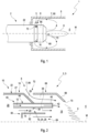
- Fig.1 shows parts of a burner system 1 extending along a central longitudinal axis M, which can be assigned in particular to the group of orifice-mixing blower burners, which are generally operated under atmospheric pressure.
- the burner system has a combustion chamber 5 and a burner head 2 arranged on the inlet side of the combustion chamber 5, comprising a mixing device 3.
- the combustion chamber 5 and the burner head 2 with the mixing device 3 are in particular designed to be rotationally symmetrical to the central longitudinal axis M.
- the combustion chamber 5 surrounds a combustion chamber 4, within which a flame with a central heat release zone 6 is formed during operation.
- a recirculation flow 7 with exhaust gas 80 is formed during operation, particularly in the radial outer region of the heat release zone 6, which causes an internal exhaust gas recirculation, i.e. formed within the combustion chamber 4.
- the mixing device 3 serves to add fresh gases (fuel 12 and oxidizer 14) into the combustion chamber 4, generating a flow distribution for mixing the different fluids participating in the combustion process (inert and/or reactive) in a mixing area 16, in particular the fresh gases and preferably internally recirculated exhaust gas 80.
- the mixing device 3 is designed such that the mixing region 16 is formed (at least largely) upstream of the combustion chamber 4. It would also be possible to design it such that the mixing region 16 is formed at least partially within the combustion chamber 4.
- the structure of the burner head 2 with the mixing device 3 is partly made of Fig.1 and more precisely from the following figures, Fig. 2 to Fig. 6 , can be seen.
- the burner head 2 comprises a burner tube 8 extending longitudinally to the central longitudinal axis M, in which the mixing region 16 is arranged.
- the burner tube 8 projects at least partially into the combustion chamber 4 and has at its downstream end a burner mouth 70 of the burner head 2 in the combustion chamber 4.
- the burner tube 8 has a guide tube section 22 and a mixing tube section 66 arranged further downstream.
- the mixing region 16 is arranged at least partially in the mixing tube section 66 and is circumferentially bordered at least in sections by the mixing tube section 66.
- the diameter of the mixing tube section 66 here corresponds, for example, at least substantially to the diameter of the guide tube section 22.
- the diameter can also be made larger or smaller, taking into account the flow distribution, in particular with regard to the recirculating exhaust gas 80. In this case, sufficient space should remain in the radially outer region for the formation of the recirculation flow 7 with recirculating exhaust gas 80.
- the burner mouth 70 of the burner head 2 in the combustion chamber 4 is formed, which in plan view looking out of the combustion chamber 4 is particularly circular.
- the opening arrangement 72 can be designed as exactly one ring-shaped circumferential opening arrangement 72 (with interposed, e.g. web-shaped fastening elements between the guide tube section 22 and the mixing tube section 66) or comprising several, in particular equivalently designed (axially and radially equally positioned and with the same shape) and/or equidistantly arranged individual openings. If there are several individual openings, these are preferably arranged at least in the direction of rotation in the area of the fuel outlet opening(s) 42. Internally recirculated exhaust gas can be sucked in through the opening arrangement 72 during operation and guided into the mixing area 16.
- Fig. 2 shows a part of the burner head 2 in longitudinal section.
- the mixing device 3 has a feed arrangement 10 with an oxidizer feed device 18.
- the oxidizer feed device 18 comprises, in the present example, precisely one feed chamber 20, which is circumferentially bordered by the guide tube section 22.
- the guide tube section 22 forms the radially outer wall of the feed chamber 20.
- the oxidizer feed device 18 comprises an oxidizer outlet opening 24, through which oxidizer 14 is added to the mixing area 16 during operation.
- the mixing tube section 66 extends axially from the oxidizer outlet opening 24 to the burner mouth 70.
- the oxidizer outlet opening 24 forms a narrowest flow cross-section 26 of the oxidizer supply device 18, at which the oxidizer flow is accelerated during operation to high axial flow velocities, preferably up to 150 m/s, for example between 80 m/s and 120 m/s.
- the guide tube section 22 is radially tapered by means of a circumferential conical section 28, starting from a cylindrical section 27, which is used here as an example, towards the narrowest flow cross-section 26, whereby a favorable flow guidance is achieved during operation.
- the guide tube section 22 at the oxidizer outlet opening 24 with the narrowest flow cross-section 26 has a cross-sectional reduction section 30.
- the cross-sectional reduction section 30 is arranged here, for example, only in the circumferential area of fuel outlet openings 42 and these are arranged radially overlapping slightly, for example by up to a diameter of the fuel outlet openings 42 on both sides.
- a fuel line 44 of a fuel supply device 40 protrudes axially through the cross-sectional reduction section 30.
- the cross-sectional reduction section 30 is also possible, for example depending on the pressure loss, to arrange the cross-sectional reduction section 30 over the entire circumferential circumference of the oxidizer outlet opening 24.
- the cross-sectional reduction section 30 is aligned steeper with respect to the cylindrical section 27 than the conical section 28, for example at an angle of approximately 90°. In this way, a further reduction in cross-section and thus an acceleration of the oxidizer flow during operation is achieved in the circumferential direction in the area of the fuel outlet openings 42 compared to the conical section 28. Due to the circumferential arrangement only in the area of the fuel outlet openings 42, the entire flow cross-section of the oxidizer outlet opening 24 can be designed to be sufficiently large in favor of a low pressure loss.
- the oxidizer outlet opening 24 is designed here, for example, as a single ring opening 19 running around the central axis M. It is also possible to have a design consisting of several individual openings arranged on a ring around the central longitudinal axis M.
- a radially inner boundary of the oxidizer outlet opening 24 is formed in the present case by an axially extending, in particular cylindrically designed combustion chamber wall 62 of a pilot stage 60 of the burner head 2.
- the combustion chamber wall 62 extends axially from upstream of the oxidizer outlet opening 24 to downstream thereof into the mixing region 16.
- the oxidizer outlet opening 24 is designed for the swirl-free, axial supply of oxidizer 14 into the mixing region 16, preferably without a radial directional component.
- the supply arrangement 10 comprises the fuel supply device 40 for adding fuel 12 into the mixing region 16, at the downstream end of which the at least one fuel outlet opening 42 is arranged.
- the fuel supply device 40 comprises one or preferably several fuel lines 44, at the downstream ends of which one of the fuel outlet openings 42 is arranged. If there are several fuel lines 44, these are preferably of the same design and/or arranged rotationally symmetrically about the central longitudinal axis M, wherein they are arranged at least partially radially at the same distance from the central longitudinal axis M and/or circumferentially equidistant from one another.
- a fuel line 44 is shown as an example.
- the fuel line 44 is in this case lance-like, elongated with a constant flow cross-section up to the fuel outlet opening 42.
- the fuel line 44 runs through the supply chamber 20 in the guide tube section 22.
- the oxidizer outlet opening 24 is arranged radially closer to the central longitudinal axis M than the respective fuel outlet opening 42, wherein the outlet openings 24, 42 do not radially overlap in the area of the cross-sectional reduction section 30 (a radial outer edge 25 of the oxidizer outlet opening 24, formed by a radial inner edge of the guide tube section 22, is the same or further away from the central longitudinal axis M than the radially innermost position of the fuel outlet opening 42).
- a radial distance r1 of the outer edge 25 of the oxidizer outlet opening 24, in the present case at the cross-sectional reduction section 30, is equal to or smaller than a smallest radial distance r2 of the fuel outlet opening 42 (with respect to its lower edge, which has the smallest radial distance of the fuel outlet opening 42 from the central longitudinal axis M) from the central longitudinal axis M.
- fuel 12 and oxidizer 14 are introduced into the mixing area 16 in the area of the cross-sectional reduction section 30 in a radially offset manner. In this way, the two fresh gases can first be premixed with exhaust gas 80 which is internally recirculated through the opening arrangement 72 and sucked into the mixing area 16.
- the fuel outlet opening 42 is arranged downstream of the opening arrangement 72 and the oxidizer outlet opening 24 within the mixing tube section 66, upstream of the burner mouth 70.
- the fuel outlet opening 42 is arranged in particular downstream of the oxidizer outlet opening 24 such that, during operation, an at least partial premixing of oxidizer 14 and the internally recirculated exhaust gas 80 takes place upstream of the fuel outlet opening 42.
- the opening arrangement 72 is preferably arranged axially in the region of the oxidizer outlet opening 24, in particular adjacent and/or overlapping upstream or downstream.
- An arrangement offset slightly upstream or downstream is also possible, but preferably upstream of the fuel outlet opening 42, such that during operation the exhaust gas is preferably sucked into the mixing region 16 upstream of the fuel outlet opening 42.
- the fuel supply device 40 is designed for swirl-free, exclusively axial supply ( Fig. 4A ) or twist-free axial-radial feed ( Fig. 4B ) of fuel 12 into the mixing area 16.
- the fuel line 44 has in particular a radially inwardly inclined end section 46.
- the radial direction component of the inclination is smaller than the axial direction component, ie the End section 46 is inclined by less than 45° relative to the axial direction (central longitudinal axis M).
- the mixing tube 66 has a conical constriction 68 at its downstream end region, which causes a flow deflection inwards during operation.
- the constriction 68 is arranged axially preferably at least partially downstream of the fuel outlet opening 42.
- the burner head 2 has a pilot stage 60 arranged centrally on the central longitudinal axis M.
- the pilot stage 60 is circumferentially surrounded by the feed arrangement 10 with the combustion chamber wall 62 of the pilot stage 60 interposed.
- the pilot stage 60 opens with a burner mouth 64 at the downstream end of the combustion chamber wall 62, axially preferably downstream of the oxidizer outlet opening 24 and upstream of the fuel outlet opening 42.
- the pilot stage 60 can be designed for operation with swirl-free flow, for example as a jet-stabilized burner, or with swirl-affected flow.
- the pilot stage 60 in its central arrangement, replaces in particular a swirl-generating baffle plate, which is often present in orifice-mixing forced draft burners known from the state of the art.
- the axial positioning of the flow openings for adding the fluids to the mixing area 16 is summarized as follows:
- the opening arrangement 72 for intake of recirculated exhaust gas 80 is positioned furthest upstream in the present example.
- the oxidizer outlet opening 24 is located at the axial position of its downstream axial end.
- the burner mouth 64 in the pilot stage 60 is arranged downstream of the oxidizer outlet opening 24 and upstream of the fuel outlet opening 42.
- the fuel outlet opening 42 is upstream of the Burner mouth 70 and preferably upstream, e.g. at the upstream end, of the constriction 68.
- oxidizer 14 is added axially into the mixing region 16 through the oxidizer outlet opening 24.
- the oxidizer flow is accelerated to the high axial flow velocities.
- the flow energy (dynamic pressure) inherent in the high flow velocities creates a negative pressure region 38 at the oxidizer outlet opening 24 and/or downstream thereof.
- Internally recirculating exhaust gas 80 is sucked in from the outside of the combustion chamber 4 into the mixing region 16 inside the burner tube 8 through the opening arrangement 72 present upstream or in the region of the negative pressure region 38.
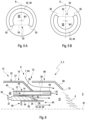
- Fig. 5A and Fig. 5B show a variant of the fuel outlet opening 42, by means of which a particularly favorable mixing of fuel 12 can be achieved within the mixing area 16.
- the fuel outlet opening 42 is designed as a gap 48 that partially surrounds a central axis M1 of the fuel line 44. Between two gap ends 50 of the partially circumferential gap 48 there is a closed side 52, without a gap. With a connecting line 54 that virtually connects the gap ends 50 via the closed side 52 (which does not intersect the partially circumferential gap 48), the partially circumferential gap 48 encloses an inner surface 56.
- a vacuum region is formed in the manner of a jet pump, particularly in the radial and circumferential region of the inner surface 56.
- the vacuum region sucks the surrounding flow, particularly from the direction of the closed side 52, into the fuel jet, into the center of the jet.
- a vortex distribution is also achieved downstream of the fuel outlet opening 42, which increases the mixing of the surrounding flow with the fuel jet.
- the partially circumferential gap 48 is mirror-symmetrical and/or rounded with respect to a plane of symmetry S of the fuel outlet opening 42 comprising the central axis M1, e.g., as in the present case, in the shape of a partial circular arc and/or U-shaped.
- the partially circumferential gap 48 is preferably formed circumferentially between 180° and 330° around the central axis M1. The remaining circumferential section is taken up by the closed side 52.
- the closed side 52 is oriented in the direction of a flow that is preferably sucked in during operation.
- the closed side 52 can be oriented radially inward, in the direction of the central longitudinal axis M (cf. Fig. 5A ). In this way, the mixing of oxidizer 14 into the fuel jet is increased.
- the closed side 52 can be oriented radially outward, in the direction of the opening arrangement 72 (cf. Fig. 5B ). In this way, the mixing of exhaust gas 80 into the fuel jet is increased.
- the exhaust gas 80 present in the mixed flow reduces the oxygen content in the mixed flow and forms a heat capacity, which reduces the NO x emissions. In this way, emissions released during combustion, in particular NO x emissions, can be minimized in an extremely advantageous manner, even without further emission reduction measures, such as external exhaust gas recirculation.
- the burner head 2 according to the invention can thus be used without modification for different fuels 12, those with high or with comparatively low reactivity (e.g. natural gas), ie with fuel flexibility.
- the fluid mixture formed within the mixing region 16, consisting of exhaust gas 80, oxidizer 14 and fuel 12, is directed radially inward into the exhaust gas flow downstream of the burner mouth 64 of the pilot stage 60.
- the fluid mixture formed in the main stage, comprising the supply arrangement 10 and the mixing region 16 is specifically ignited in this region by means of the pilot stage 60.
- the pilot stage 60 is operated with a higher combustion air ratio (e.g. ⁇ > 1.5) than the main stage, which is preferably operated with a combustion air ratio of ⁇ ⁇ 1.2. In total, an almost stoichiometric operation or an operation with excess air should take place.
- the mixing device 3 uses the high speed of the oxidizer 14 at the narrowest flow cross-section 26 to generate the negative pressure region 38 in the manner of a jet pump.
- the burner head 2 preferably has an adjustment device 32 for reducing the narrowest flow cross-section 26, in particular in the partial load range.
- the adjustment device 32 has an axially displaceable adjustment body 34, which can be displaced into the narrowest cross section 26 by means of a wedge section 36.
- the axial displacement takes place outside or during operation, for example by means of a servomotor, the driving force of which is transmitted to the adjustment body 34 by means of at least one force transmission device 37.
- the partial section 36 enables a continuous change of the narrowest flow cross-section 26, in particular in correlation with the mass flow of oxidizer 14, up to a complete closure of the flow cross-section 26. By closing it when the burner system 1 is switched off, a subsequent flow of oxidizer 14 can be prevented.
- the adjusting body 34 is adapted in particular in its shape to the geometry of the oxidizer supply device 18, in particular the oxidizer outlet opening 24, and/or the fuel supply device 40.
- the adjusting body 34 can also be designed in a circumferential ring shape.
- the narrowest flow cross-section 26 is adjusted by means of the adjustment device 32, for example in correlation to the mass flow of the oxidizer 14 in order to adjust the speed of the oxidizer flow at the narrowest flow cross-section 26.
- the aim is to maintain the speed at the narrowest cross-section 26 at the highest possible level, ideally corresponding to the speed range in the full load range of up to 150 m/s, e.g. between 80 m/s and 120 m/s. In this way, the pressure level in the negative pressure region 38, which is correlated with the strength of the intake effect on the exhaust gas 80 and the associated reduction in NO x emissions, is maintained.
- an air flap usually present in forced draught burners upstream of the burner head 2 for regulating or throttling the oxidizer flow is replaced by the adjustment device 32 (not shown here).
- the pressure loss generated by this air flap is thus prevented, particularly in the low/partial load range and in the medium load range, and is locally shifted to the narrowest flow cross-section 26, whereby the flow energy is not lost but is effectively used to generate the suction effect on the exhaust gas flow.
- the pilot stage 60 can also have an adjusting device which is suitably designed to reduce the oxidizer mass flow through the pilot stage (not shown here).
- a burner head 2 is thus provided, by means of which operation with an extremely low emission level for differently reactive fuels, in particular combustion gases, over a wide operating range is made possible with comparatively little effort.
Landscapes
- Engineering & Computer Science (AREA)
- Chemical & Material Sciences (AREA)
- Combustion & Propulsion (AREA)
- Mechanical Engineering (AREA)
- General Engineering & Computer Science (AREA)
- Gas Burners (AREA)
Applications Claiming Priority (1)
| Application Number | Priority Date | Filing Date | Title |
|---|---|---|---|
| DE102023102016.1A DE102023102016A1 (de) | 2023-01-27 | 2023-01-27 | Brennerkopf, Brennersystem und Verfahren zum Betreiben eines Brennersystems |
Publications (2)
| Publication Number | Publication Date |
|---|---|
| EP4407231A2 true EP4407231A2 (fr) | 2024-07-31 |
| EP4407231A3 EP4407231A3 (fr) | 2024-11-27 |
Family
ID=89723304
Family Applications (1)
| Application Number | Title | Priority Date | Filing Date |
|---|---|---|---|
| EP24154006.1A Pending EP4407231A3 (fr) | 2023-01-27 | 2024-01-25 | Tête de brûleur, système de brûleur et procédé de fonctionnement d'un système de brûleur |
Country Status (2)
| Country | Link |
|---|---|
| EP (1) | EP4407231A3 (fr) |
| DE (1) | DE102023102016A1 (fr) |
Citations (5)
| Publication number | Priority date | Publication date | Assignee | Title |
|---|---|---|---|---|
| DE3920078A1 (de) | 1988-06-21 | 1989-12-28 | Dreizler Walter Dipl Ing Fh | Brennerkopf fuer einen geblaesegasbrenner |
| US20120183914A1 (en) | 2006-06-14 | 2012-07-19 | John Zink Company, Llc | Coanda gas burner apparatus and methods |
| DE102016125526B3 (de) | 2016-12-22 | 2018-05-30 | Max Weishaupt Gmbh | Mischvorrichtung und Brennerkopf für einen Brenner mit reduziertem NOx-Ausstoß |
| US11226096B2 (en) | 2016-08-25 | 2022-01-18 | Zhongshan Gda Gas Valve Co., Ltd. | Heater with valve configuration |
| KR102437328B1 (ko) | 2021-12-22 | 2022-08-30 | 한국에너지기술연구원 | 내부 배기가스 재순환 예혼합형 공업용 가스연소기 및 그 작동방법 |
Family Cites Families (3)
| Publication number | Priority date | Publication date | Assignee | Title |
|---|---|---|---|---|
| EP0194079B1 (fr) * | 1985-02-21 | 1989-10-25 | Tauranca Limited | Brûleur à combustible liquide |
| US11226092B2 (en) * | 2016-09-22 | 2022-01-18 | Utilization Technology Development, Nfp | Low NOx combustion devices and methods |
| CN217131272U (zh) * | 2020-11-25 | 2022-08-05 | 百得股份公司 | 减少排放的工业燃烧器和设备 |
-
2023
- 2023-01-27 DE DE102023102016.1A patent/DE102023102016A1/de active Pending
-
2024
- 2024-01-25 EP EP24154006.1A patent/EP4407231A3/fr active Pending
Patent Citations (5)
| Publication number | Priority date | Publication date | Assignee | Title |
|---|---|---|---|---|
| DE3920078A1 (de) | 1988-06-21 | 1989-12-28 | Dreizler Walter Dipl Ing Fh | Brennerkopf fuer einen geblaesegasbrenner |
| US20120183914A1 (en) | 2006-06-14 | 2012-07-19 | John Zink Company, Llc | Coanda gas burner apparatus and methods |
| US11226096B2 (en) | 2016-08-25 | 2022-01-18 | Zhongshan Gda Gas Valve Co., Ltd. | Heater with valve configuration |
| DE102016125526B3 (de) | 2016-12-22 | 2018-05-30 | Max Weishaupt Gmbh | Mischvorrichtung und Brennerkopf für einen Brenner mit reduziertem NOx-Ausstoß |
| KR102437328B1 (ko) | 2021-12-22 | 2022-08-30 | 한국에너지기술연구원 | 내부 배기가스 재순환 예혼합형 공업용 가스연소기 및 그 작동방법 |
Also Published As
| Publication number | Publication date |
|---|---|
| DE102023102016A1 (de) | 2024-08-01 |
| EP4407231A3 (fr) | 2024-11-27 |
Similar Documents
| Publication | Publication Date | Title |
|---|---|---|
| EP2116766B1 (fr) | Brûleur avec lance à combustible | |
| DE69523082T2 (de) | Brennstoffdüse einer Turbine mit doppelter Möglichkeit zur Diffusions- und Vormischverbrennung und Verfahren zum Betrieb | |
| DE3217674C2 (de) | Brennkammer für eine Gasturbine | |
| DE60017426T2 (de) | Verstellbare magerbetriebene vormischbrennkammer | |
| DE69614547T2 (de) | Brenner | |
| EP2156095B1 (fr) | Stabilisation sans tourbillonner de la flamme d'un brûleur à prémélange | |
| EP1262714A1 (fr) | Brûleur avec recirculation des gaz de combustion | |
| EP0718561B1 (fr) | Brûleur | |
| DE4241883A1 (de) | Mehrstufiger Brenner | |
| DE2629761A1 (de) | Brennkammer fuer gasturbinen | |
| DE102016125526B3 (de) | Mischvorrichtung und Brennerkopf für einen Brenner mit reduziertem NOx-Ausstoß | |
| WO2008092795A1 (fr) | Chambre de combustion pour une turbine à gaz | |
| CH710573A2 (de) | Brennstoffdüse für eine Gasturbinenbrennkammer. | |
| CH708992A2 (de) | Brennstoffinjektor mit Vormisch-Pilotdüse. | |
| EP0571704A2 (fr) | Brûleur pour combustible pulvérulent | |
| EP0692675A2 (fr) | Procédé et dispositif pour la mise en oeuvre d'un brûleur combiné à combustibles liquides et gazeux | |
| EP0775869A2 (fr) | Brûleur à prémélange | |
| DE3741021C2 (de) | Brennkammer für ein Gasturbinentriebwerk | |
| DE102020118325A1 (de) | Verfahren zur gestuften verbrennung eines brennstoffes und brennkopf | |
| EP2037173B1 (fr) | Tête de brûleur et procédé de combustion à un étage de combustible dans une zone de combustion éloignée de la tête de brûleur | |
| EP1754937B1 (fr) | Tête de brûleur et procédé pour brûler du combustible | |
| EP4407231A2 (fr) | Tête de brûleur, système de brûleur et procédé de fonctionnement d'un système de brûleur | |
| EP0602396A1 (fr) | Générateur de chaleur pour processus industriel | |
| DE69608076T2 (de) | Verbrennungsverfahren und Vorrichtung mit niedriger Stickstoffoxid-Erzeugung | |
| DE102017118166B4 (de) | Brennerkopf, Brennersystem und Verwendung des Brennersystems |
Legal Events
| Date | Code | Title | Description |
|---|---|---|---|
| PUAI | Public reference made under article 153(3) epc to a published international application that has entered the european phase |
Free format text: ORIGINAL CODE: 0009012 |
|
| STAA | Information on the status of an ep patent application or granted ep patent |
Free format text: STATUS: THE APPLICATION HAS BEEN PUBLISHED |
|
| AK | Designated contracting states |
Kind code of ref document: A2 Designated state(s): AL AT BE BG CH CY CZ DE DK EE ES FI FR GB GR HR HU IE IS IT LI LT LU LV MC ME MK MT NL NO PL PT RO RS SE SI SK SM TR |
|
| PUAL | Search report despatched |
Free format text: ORIGINAL CODE: 0009013 |
|
| AK | Designated contracting states |
Kind code of ref document: A3 Designated state(s): AL AT BE BG CH CY CZ DE DK EE ES FI FR GB GR HR HU IE IS IT LI LT LU LV MC ME MK MT NL NO PL PT RO RS SE SI SK SM TR |
|
| RIC1 | Information provided on ipc code assigned before grant |
Ipc: F23D 14/70 20060101ALI20241024BHEP Ipc: F23D 14/64 20060101ALI20241024BHEP Ipc: F23D 14/02 20060101ALI20241024BHEP Ipc: F23C 9/00 20060101AFI20241024BHEP |
|
| STAA | Information on the status of an ep patent application or granted ep patent |
Free format text: STATUS: REQUEST FOR EXAMINATION WAS MADE |
|
| 17P | Request for examination filed |
Effective date: 20250527 |
|
| STAA | Information on the status of an ep patent application or granted ep patent |
Free format text: STATUS: EXAMINATION IS IN PROGRESS |
|
| 17Q | First examination report despatched |
Effective date: 20250910 |
|
| GRAP | Despatch of communication of intention to grant a patent |
Free format text: ORIGINAL CODE: EPIDOSNIGR1 |
|
| STAA | Information on the status of an ep patent application or granted ep patent |
Free format text: STATUS: GRANT OF PATENT IS INTENDED |
|
| INTG | Intention to grant announced |
Effective date: 20260306 |