EP0602396A1 - Générateur de chaleur pour processus industriel - Google Patents
Générateur de chaleur pour processus industriel Download PDFInfo
- Publication number
- EP0602396A1 EP0602396A1 EP93118406A EP93118406A EP0602396A1 EP 0602396 A1 EP0602396 A1 EP 0602396A1 EP 93118406 A EP93118406 A EP 93118406A EP 93118406 A EP93118406 A EP 93118406A EP 0602396 A1 EP0602396 A1 EP 0602396A1
- Authority
- EP
- European Patent Office
- Prior art keywords
- combustion
- heat generator
- process heat
- zone
- generator according
- Prior art date
- Legal status (The legal status is an assumption and is not a legal conclusion. Google has not performed a legal analysis and makes no representation as to the accuracy of the status listed.)
- Granted
Links
Images


Classifications
-
- F—MECHANICAL ENGINEERING; LIGHTING; HEATING; WEAPONS; BLASTING
- F23—COMBUSTION APPARATUS; COMBUSTION PROCESSES
- F23C—METHODS OR APPARATUS FOR COMBUSTION USING FLUID FUEL OR SOLID FUEL SUSPENDED IN A CARRIER GAS OR AIR
- F23C7/00—Combustion apparatus characterised by arrangements for air supply
- F23C7/002—Combustion apparatus characterised by arrangements for air supply the air being submitted to a rotary or spinning motion
-
- F—MECHANICAL ENGINEERING; LIGHTING; HEATING; WEAPONS; BLASTING
- F23—COMBUSTION APPARATUS; COMBUSTION PROCESSES
- F23C—METHODS OR APPARATUS FOR COMBUSTION USING FLUID FUEL OR SOLID FUEL SUSPENDED IN A CARRIER GAS OR AIR
- F23C6/00—Combustion apparatus characterised by the combination of two or more combustion chambers or combustion zones, e.g. for staged combustion
- F23C6/04—Combustion apparatus characterised by the combination of two or more combustion chambers or combustion zones, e.g. for staged combustion in series connection
-
- F—MECHANICAL ENGINEERING; LIGHTING; HEATING; WEAPONS; BLASTING
- F23—COMBUSTION APPARATUS; COMBUSTION PROCESSES
- F23C—METHODS OR APPARATUS FOR COMBUSTION USING FLUID FUEL OR SOLID FUEL SUSPENDED IN A CARRIER GAS OR AIR
- F23C9/00—Combustion apparatus characterised by arrangements for returning combustion products or flue gases to the combustion chamber
-
- F—MECHANICAL ENGINEERING; LIGHTING; HEATING; WEAPONS; BLASTING
- F23—COMBUSTION APPARATUS; COMBUSTION PROCESSES
- F23C—METHODS OR APPARATUS FOR COMBUSTION USING FLUID FUEL OR SOLID FUEL SUSPENDED IN A CARRIER GAS OR AIR
- F23C2900/00—Special features of, or arrangements for combustion apparatus using fluid fuels or solid fuels suspended in air; Combustion processes therefor
- F23C2900/07002—Premix burners with air inlet slots obtained between offset curved wall surfaces, e.g. double cone burners
Definitions
- the present invention relates to a process heat generator according to the preamble of claim 1.
- a staged combustion is used when using nitrogenous fuels such as heavy oil, coal etc.
- nitrogenous fuels such as heavy oil, coal etc.
- This combustion is a process in which a process medium is heated in two stages.
- the fuel oil and gas premixed with air in a combustion device is partially burned sub-stoichiometrically with an air ratio of 0.5-0.98 in a pre-combustion chamber which functions as a first stage.
- the partially burned, low-nitrogen oxide mixture reaches a temperature of 1800-1900 ° C and heats the process medium, which has already been preheated to an intermediate temperature, to its final temperature in a heat exchanger placed at the transition to an afterburning zone.
- the partially burned batch is in an air injection area of the process heat generator Air mixed in a stoichiometric ratio with respect to the unburned components and thereby completely burned in the afterburning zone, thereby reducing the nitrogen compounds formed.
- this circuit has shown that the substantial reduction in nitrogen oxides cannot achieve the minimization that will be necessary in the future for the strictest emission limits of such systems. It has become known that the desired NOx reduction can be achieved through the use of additives. However, such a circuit lacks acceptance by the operator.
- the invention seeks to remedy this.
- the object of the invention is to propose a circuit for a process heat generator of the type mentioned at the outset which enables a further reduction in the NOx emission values.
- the main advantage of the invention can be seen in the fact that the process in this process heat generator can also be operated via a two-stage or multi-stage combustion with or without premixing zones in the second stage of the known type. It is important to consider those measures in which the gas temperature from the first flame front is lowered in a targeted manner. This activates reaction-kinetic processes in a limited, optimal temperature range, in which the nitrogen compounds still present in the reaction zone adjoining the heat exchanger are drastically reduced again.
- Another important advantage of the invention is that the process takes place through reactions of the naturally occurring NHx radicals with one another and with the nitrogen oxides, without the need to use additives.
- FIG. 1 shows a process heat generator which essentially consists of a burner device and two combustion stages or combustion zones.
- a further combustion stage can be provided downstream of the second combustion stage, in which, for example, combustion can be carried out with a tertiary air mass flow.
- the third and possibly the following combustion stages can have features of the first and / or the second stage.
- the burner device for liquid and / or gaseous fuels already mentioned as a heating medium.
- a premix burner 101 the physical configuration of which is described in more detail in FIGS. 2-5, is particularly suitable as the burner device for the method used here.
- a liquid fuel 12 is fed via at least one centrally placed nozzle and preferably a gaseous fuel is fed in via further fuel nozzles which are located in the area of the air inlet slots into the interior of the burner 101.
- An ignitable mixture is formed in the burner 101, the reaction zone 103 extending from this combustion to the flame front of this burner.
- the pre-combustion zone 107 is the inflow of an air duct 105 which is concentric with respect to this zone and via which a primary air 106 is fed to the burner 101.
- the air duct 105 serves as an air heater for the primary air 106, as a result of which the burner 101 is supplied with a calorically prepared combustion air stream 15.
- the primary air stream 106 can be used to cool the reduction stage 104 downstream of the reaction stage 103.
- This caloric treatment of the primary air 106 before the substoichiometric combustion process results in optimal process control, since the requirement of NOx formation by both HCN and NH3 is avoided as far as possible.
- this combustion takes place sub-stoichiometrically, namely within an optimal value with an air ratio lambda of 0.5-0.98.
- the fuel-bound nitrogen in the reaction zone 103 is partly reduced and partly converted into NO and NHx radicals in an optimal stoichiometric ratio.
- the gas temperature from the flame front of the reaction zone 103 is specifically reduced by means of an immediately following heat exchanger 108 of any type.
- reaction kinetic processes are activated in a limited optimal temperature range, in which the nitrogen compounds still present within the reaction zone 104 following the heat exchanger 108 are again drastically reduced. This is done by reactions of the naturally occurring NHx radicals with one another and with the nitrogen oxides, without the need to use additives, for example.
- a cooled exhaust gas 112 is optimally supplied to the combustion gases upstream of this afterburning zone 110, individually or together with a residual air supply 109, which passes through a second downstream of the afterburning zone 110 acting heat exchanger 11 is provided. If opting for a residual air / exhaust gas supply, the substoichiometric gases in front of or within the afterburning zone 110 are fed with a mixture 114 of air and exhaust gas. As a result, after the admixture of this mixture for the afterburning zone 110 and its complete burnout, the desired final temperature is reached, which is now so low that no significant thermal nitrogen oxides are produced.
- the system of heat exchangers 108, 111 is how shows the cable routing from the figure, designed as a series circuit, whereby of course a parallel connection is also possible.
- the heat exchanger 108 can also be used for the calorific preparation of the primary air 106 instead of further heating the process medium.
- the delivery of the necessary exhaust gases downstream of the heat exchanger 111 is maintained by various blowers or jet pumps 113.
- the remaining waste gases 115 that are not required are sent to the chimney or to another consumer.
- the process medium to be preheated is calorically processed in the heat exchangers 108 and 111 connected here in succession, the process medium in the heat exchanger 108 being heated to its final temperature and fed to the point of use via a process medium discharge line 116.
- FIG. 2 In order to be able to understand the structure of the burner 101 straight away, it is advantageous if, at the same time, the individual sections shown in FIG. 2, which form FIGS. 3-5, are used. Furthermore, in order to make the physical design of the burner as clear as possible, the guide plates 21a, 21b shown schematically in FIGS. 3-5 have only been hinted at in FIG. 2. In the following, reference is made to the following figures when necessary in the description of FIG. 2.
- the burner 101 according to FIG. 2 consists of two half hollow conical partial bodies 1, 2 which are offset from one another with respect to their central axes.
- the offset is preferably provided radially in one plane, so that the two central axes run parallel to one another in the same plane.
- a tangential air inlet slot 19, 20 is created on both sides of the conical sub-bodies 1, 2 in the opposite inflow arrangement (cf. 3-5), through which the combustion air 15 already described in FIG. 1 flows into the conical interior 14 formed by the conical partial bodies 1, 2.
- the conical shape of the partial bodies 1, 2 shown has a certain fixed angle in the direction of flow.
- the partial bodies 1, 2 can have a progressive (trumpet-shaped) or degressive (tulip-shaped) taper in the direction of flow. The last two forms are not included in the drawing, since they can be easily modeled.
- the two conical partial bodies 1, 2 each have a cylindrical initial part 1a, 2a, which, analogous to the partial bodies 1, 2, are offset from one another, so that the tangential air inlet slots 19, 20 are present continuously over the entire length of the burner 101.
- These initial parts can also take on a different geometric shape, and sometimes they can be left out entirely.
- a nozzle 3 is accommodated within this cylindrical initial part 1a, 2a, via which a fuel 12, preferably oil, or a fuel mixture is injected into the interior 14 of the burner 101. This fuel injection 4 coincides approximately with the narrowest cross section of the interior 14.
- This admixture takes place in the area of the entry into the interior 14, this by an optimal speed-related To achieve admixture 16.
- Mixed operation with both fuels 12, 13 via the respective injection is of course possible.
- the outlet opening of the burner 101 merges into a front wall 10, in which a number of bores 10a are provided, in order to inject a certain amount of dilution air or cooling air into the pre-combustion zone 107 if required.
- the liquid fuel 12 provided by the nozzle 3 is injected into the interior 14 of the burner 101 at an acute angle, in such a way that the most homogeneous conical spray pattern occurs over the entire length of the burner 101 up to the burner outlet level, which is only possible if the inner walls of the partial bodies 1, 2 are not wetted by the fuel injection 4, which is, for example, an air-assisted nozzle or pressure atomization.
- the conical liquid fuel profile 5 is surrounded by the tangentially flowing combustion air 15 and, if necessary, by a further axially brought-in combustion air flow 15a.
- the concentration of the injected liquid fuel 12, which may be a fuel or fuel / combustion air mixture, is continuously increased by the combustion air 15 flowing into the interior 14 of the burner 101 through the tangential air inlet slots 19, 20 , which can be a fuel / air or fuel / air / exhaust gas mixture, and if necessary with the help of the other combustion air flow 15a, continuously reduced.
- the optimal homogeneous fuel concentration over the cross-section is achieved in the area of the vortexing, ie in the area of the backflow zone 6.
- the ignition takes place at the top of the backflow zone. Only at this point can a stable flame front 7 arise.
- combustion air 15, 15a is preheated, as is the case here with a heat exchanger, accelerated integral evaporation of the fuel occurs within the premixing section of the burner 101, i.e. before the point at the outlet of the burner 101 is reached at which the ignition of the mixture takes place.
- the preparation of the combustion air streams 15, 15a can be expanded by adding recirculated exhaust gas, not shown in FIG. 1, analogously to the afterburning zone (FIG. 1, item 110).
- the axial velocity of the flow within the burner 101 can be changed by a corresponding supply of the axial combustion air flow 15a.
- the design of the burner 101 is excellently suited to changing the cross sections of the tangential air inlet slots 19, 20 according to requirements, with which a relatively large operating bandwidth can be recorded without changing the overall length of the burner 101.
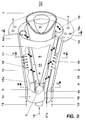
- FIG. 3-5 shows the geometrical configuration of the guide plates 21a, 21b.
- the combustion air flow 15 into the interior 14 of the burner 101 they have to perform flow introduction functions.
- a channeling effect or a change in speed of the combustion air flow 15 can be optimized by opening or closing the guide plates 21a, 21b around a pivot point 23 placed in the region of the tangential air inlet slots 19, 20, in particular this is necessary if the original gap size of the tangential air inlet slots 19, 20 is changed.
- the burner 101 can also be operated without baffles 21a, 21b, or other aids can be provided for this.
Landscapes
- Engineering & Computer Science (AREA)
- Chemical & Material Sciences (AREA)
- Combustion & Propulsion (AREA)
- Mechanical Engineering (AREA)
- General Engineering & Computer Science (AREA)
Applications Claiming Priority (2)
| Application Number | Priority Date | Filing Date | Title |
|---|---|---|---|
| DE4242003 | 1992-12-12 | ||
| DE4242003A DE4242003A1 (de) | 1992-12-12 | 1992-12-12 | Prozesswärmeerzeuger |
Publications (2)
| Publication Number | Publication Date |
|---|---|
| EP0602396A1 true EP0602396A1 (fr) | 1994-06-22 |
| EP0602396B1 EP0602396B1 (fr) | 1998-08-19 |
Family
ID=6475129
Family Applications (1)
| Application Number | Title | Priority Date | Filing Date |
|---|---|---|---|
| EP93118406A Expired - Lifetime EP0602396B1 (fr) | 1992-12-12 | 1993-11-13 | Méthode de exploitation d'un générateur de chaleur |
Country Status (2)
| Country | Link |
|---|---|
| EP (1) | EP0602396B1 (fr) |
| DE (2) | DE4242003A1 (fr) |
Cited By (6)
| Publication number | Priority date | Publication date | Assignee | Title |
|---|---|---|---|---|
| DE4436728A1 (de) * | 1994-10-14 | 1996-04-18 | Abb Research Ltd | Verfahren und Vorrichtung für eine schadstoffarme gestufte Verbrennung |
| DE4446541A1 (de) * | 1994-12-24 | 1996-06-27 | Abb Management Ag | Brennkammer |
| DE19510744A1 (de) * | 1995-03-24 | 1996-09-26 | Abb Management Ag | Brennkammer mit Zweistufenverbrennung |
| DE19537636A1 (de) * | 1995-10-10 | 1997-04-17 | Asea Brown Boveri | Verfahren zum Betrieb einer Kraftwerksanlage |
| CN107087819A (zh) * | 2017-06-14 | 2017-08-25 | 深圳市新宜康科技有限公司 | 旋流电子烟雾化器结构及其旋流电子烟雾化器 |
| US11226092B2 (en) * | 2016-09-22 | 2022-01-18 | Utilization Technology Development, Nfp | Low NOx combustion devices and methods |
Families Citing this family (4)
| Publication number | Priority date | Publication date | Assignee | Title |
|---|---|---|---|---|
| DE4422535A1 (de) * | 1994-06-28 | 1996-01-04 | Abb Research Ltd | Verfahren zum Betrieb einer Feuerungsanlage |
| DE4444125A1 (de) * | 1994-12-12 | 1996-06-13 | Abb Research Ltd | Verfahren zur schadstoffarmen Verbrennung |
| DE19505753A1 (de) * | 1995-02-20 | 1996-08-22 | Abb Research Ltd | Verfahren zur schadstoffarmen Verbrennung von flüssigem Brennstoff in einem Heizungskessel |
| DE19724929B4 (de) * | 1997-06-12 | 2007-04-12 | Fritz Dr.-Ing. Schoppe | Brennverfahren für Staubfeuerungen kleiner Leistung |
Citations (4)
| Publication number | Priority date | Publication date | Assignee | Title |
|---|---|---|---|---|
| EP0047346A1 (fr) * | 1980-09-01 | 1982-03-17 | John Zink Company | Elimination d'oxydes azotiques et récupération de chaleur dans un dispositif combiné |
| DE3707773A1 (de) * | 1987-03-11 | 1988-09-22 | Bbc Brown Boveri & Cie | Verfahren und einrichtung zur prozesswaermeerzeugung |
| EP0436113A1 (fr) * | 1989-12-01 | 1991-07-10 | Asea Brown Boveri Ag | Procédé pour le fonctionnement d'une installation de combustion |
| EP0545114A1 (fr) * | 1991-12-05 | 1993-06-09 | Asea Brown Boveri Ag | Procédé pour la production de chaleur industrielle |
Family Cites Families (2)
| Publication number | Priority date | Publication date | Assignee | Title |
|---|---|---|---|---|
| AT391185B (de) * | 1988-02-08 | 1990-08-27 | Vaillant Gmbh | Einrichtung zur stufenweisen verbrennung eines brennstoff-luftgemisches |
| CH680467A5 (fr) * | 1989-12-22 | 1992-08-31 | Asea Brown Boveri |
-
1992
- 1992-12-12 DE DE4242003A patent/DE4242003A1/de not_active Withdrawn
-
1993
- 1993-11-13 EP EP93118406A patent/EP0602396B1/fr not_active Expired - Lifetime
- 1993-11-13 DE DE59308888T patent/DE59308888D1/de not_active Expired - Fee Related
Patent Citations (4)
| Publication number | Priority date | Publication date | Assignee | Title |
|---|---|---|---|---|
| EP0047346A1 (fr) * | 1980-09-01 | 1982-03-17 | John Zink Company | Elimination d'oxydes azotiques et récupération de chaleur dans un dispositif combiné |
| DE3707773A1 (de) * | 1987-03-11 | 1988-09-22 | Bbc Brown Boveri & Cie | Verfahren und einrichtung zur prozesswaermeerzeugung |
| EP0436113A1 (fr) * | 1989-12-01 | 1991-07-10 | Asea Brown Boveri Ag | Procédé pour le fonctionnement d'une installation de combustion |
| EP0545114A1 (fr) * | 1991-12-05 | 1993-06-09 | Asea Brown Boveri Ag | Procédé pour la production de chaleur industrielle |
Cited By (9)
| Publication number | Priority date | Publication date | Assignee | Title |
|---|---|---|---|---|
| DE4436728A1 (de) * | 1994-10-14 | 1996-04-18 | Abb Research Ltd | Verfahren und Vorrichtung für eine schadstoffarme gestufte Verbrennung |
| DE4446541A1 (de) * | 1994-12-24 | 1996-06-27 | Abb Management Ag | Brennkammer |
| DE19510744A1 (de) * | 1995-03-24 | 1996-09-26 | Abb Management Ag | Brennkammer mit Zweistufenverbrennung |
| US5829967A (en) * | 1995-03-24 | 1998-11-03 | Asea Brown Boveri Ag | Combustion chamber with two-stage combustion |
| DE19537636A1 (de) * | 1995-10-10 | 1997-04-17 | Asea Brown Boveri | Verfahren zum Betrieb einer Kraftwerksanlage |
| DE19537636B4 (de) * | 1995-10-10 | 2004-02-12 | Alstom | Kraftwerksanlage |
| US11226092B2 (en) * | 2016-09-22 | 2022-01-18 | Utilization Technology Development, Nfp | Low NOx combustion devices and methods |
| CN107087819A (zh) * | 2017-06-14 | 2017-08-25 | 深圳市新宜康科技有限公司 | 旋流电子烟雾化器结构及其旋流电子烟雾化器 |
| CN107087819B (zh) * | 2017-06-14 | 2023-10-20 | 深圳市新宜康科技股份有限公司 | 旋流电子烟雾化器结构及旋流电子烟雾化器 |
Also Published As
| Publication number | Publication date |
|---|---|
| EP0602396B1 (fr) | 1998-08-19 |
| DE4242003A1 (de) | 1994-06-16 |
| DE59308888D1 (de) | 1998-09-24 |
Similar Documents
| Publication | Publication Date | Title |
|---|---|---|
| EP0436113B1 (fr) | Procédé pour le fonctionnement d'une installation de combustion | |
| DE69828916T2 (de) | Emissionsarmes Verbrennungssystem für Gasturbinentriebwerke | |
| EP0571782B1 (fr) | Procédé de fonctionnement d'une chambre de combustion pour turbine à gaz | |
| DE69724502T2 (de) | Gasturbinenbrennkammer | |
| EP0629817B1 (fr) | Foyer | |
| EP0713058A1 (fr) | Chambre de combustion à plusieurs étage | |
| EP0694740A2 (fr) | Chambre de combustion | |
| DE4326802A1 (de) | Brennstofflanze für flüssige und/oder gasförmige Brennstoffe sowie Verfahren zu deren Betrieb | |
| EP0392158B1 (fr) | Procédé pour le fonctionnement d'une installation de combustion pour combustibles fossiles | |
| EP0718561A2 (fr) | Brûleur | |
| EP0481111B1 (fr) | Chambre de combustion pour turbine à gaz | |
| CH680467A5 (fr) | ||
| EP0521325B1 (fr) | Chambre de combustion | |
| EP0401529A1 (fr) | Chambre de combustion d'une turbine à gaz | |
| EP0777081A2 (fr) | Brûleur à prémélange | |
| EP0394911B1 (fr) | Installation de combustion | |
| EP0433789A1 (fr) | Procédé d'une combustion à mélange préalable d'un combustible liquide | |
| EP0394800A1 (fr) | Brûleur à mélange préalable pour la génération de gaz chaud | |
| EP0602396B1 (fr) | Méthode de exploitation d'un générateur de chaleur | |
| EP0483554B1 (fr) | Procédé pour la réduction au minimum des émissions de NOx dans une combustion | |
| EP0510783B1 (fr) | Dispositif pour la combustion des combustibles fluides ou gazeux | |
| EP0690263B1 (fr) | Procédé pour le fonctionnement d'une installation de combustion | |
| DE69608076T2 (de) | Verbrennungsverfahren und Vorrichtung mit niedriger Stickstoffoxid-Erzeugung | |
| EP0961905B1 (fr) | Procede et dispositif de combustion d'un combustible | |
| DE102005038662B4 (de) | Brennkopf und Verfahren zur Verbrennung von Brennstoff |
Legal Events
| Date | Code | Title | Description |
|---|---|---|---|
| PUAI | Public reference made under article 153(3) epc to a published international application that has entered the european phase |
Free format text: ORIGINAL CODE: 0009012 |
|
| AK | Designated contracting states |
Kind code of ref document: A1 Designated state(s): DE FR IT NL |
|
| 17P | Request for examination filed |
Effective date: 19941125 |
|
| 17Q | First examination report despatched |
Effective date: 19960916 |
|
| GRAG | Despatch of communication of intention to grant |
Free format text: ORIGINAL CODE: EPIDOS AGRA |
|
| GRAG | Despatch of communication of intention to grant |
Free format text: ORIGINAL CODE: EPIDOS AGRA |
|
| GRAH | Despatch of communication of intention to grant a patent |
Free format text: ORIGINAL CODE: EPIDOS IGRA |
|
| GRAH | Despatch of communication of intention to grant a patent |
Free format text: ORIGINAL CODE: EPIDOS IGRA |
|
| GRAA | (expected) grant |
Free format text: ORIGINAL CODE: 0009210 |
|
| AK | Designated contracting states |
Kind code of ref document: B1 Designated state(s): DE FR IT NL |
|
| REF | Corresponds to: |
Ref document number: 59308888 Country of ref document: DE Date of ref document: 19980924 |
|
| ET | Fr: translation filed | ||
| PLBE | No opposition filed within time limit |
Free format text: ORIGINAL CODE: 0009261 |
|
| STAA | Information on the status of an ep patent application or granted ep patent |
Free format text: STATUS: NO OPPOSITION FILED WITHIN TIME LIMIT |
|
| 26N | No opposition filed | ||
| PGFP | Annual fee paid to national office [announced via postgrant information from national office to epo] |
Ref country code: NL Payment date: 20011031 Year of fee payment: 9 Ref country code: DE Payment date: 20011031 Year of fee payment: 9 |
|
| PGFP | Annual fee paid to national office [announced via postgrant information from national office to epo] |
Ref country code: FR Payment date: 20011106 Year of fee payment: 9 |
|
| NLS | Nl: assignments of ep-patents |
Owner name: ALSTOM |
|
| PG25 | Lapsed in a contracting state [announced via postgrant information from national office to epo] |
Ref country code: NL Free format text: LAPSE BECAUSE OF NON-PAYMENT OF DUE FEES Effective date: 20030601 |
|
| PG25 | Lapsed in a contracting state [announced via postgrant information from national office to epo] |
Ref country code: DE Free format text: LAPSE BECAUSE OF NON-PAYMENT OF DUE FEES Effective date: 20030603 |
|
| PG25 | Lapsed in a contracting state [announced via postgrant information from national office to epo] |
Ref country code: FR Free format text: LAPSE BECAUSE OF NON-PAYMENT OF DUE FEES Effective date: 20030731 |
|
| NLV4 | Nl: lapsed or anulled due to non-payment of the annual fee |
Effective date: 20030601 |
|
| REG | Reference to a national code |
Ref country code: FR Ref legal event code: ST |
|
| PG25 | Lapsed in a contracting state [announced via postgrant information from national office to epo] |
Ref country code: IT Free format text: LAPSE BECAUSE OF NON-PAYMENT OF DUE FEES Effective date: 20051113 |