EP4407732A1 - Sekundärbatterie, batteriemodul, batteriepack und elektrische vorrichtung - Google Patents
Sekundärbatterie, batteriemodul, batteriepack und elektrische vorrichtung Download PDFInfo
- Publication number
- EP4407732A1 EP4407732A1 EP22939246.9A EP22939246A EP4407732A1 EP 4407732 A1 EP4407732 A1 EP 4407732A1 EP 22939246 A EP22939246 A EP 22939246A EP 4407732 A1 EP4407732 A1 EP 4407732A1
- Authority
- EP
- European Patent Office
- Prior art keywords
- group
- optionally
- secondary battery
- positive electrode
- mol
- Prior art date
- Legal status (The legal status is an assumption and is not a legal conclusion. Google has not performed a legal analysis and makes no representation as to the accuracy of the status listed.)
- Pending
Links
Images

Classifications
-
- H—ELECTRICITY
- H01—ELECTRIC ELEMENTS
- H01M—PROCESSES OR MEANS, e.g. BATTERIES, FOR THE DIRECT CONVERSION OF CHEMICAL ENERGY INTO ELECTRICAL ENERGY
- H01M10/00—Secondary cells; Manufacture thereof
- H01M10/05—Accumulators with non-aqueous electrolyte
- H01M10/052—Li-accumulators
- H01M10/0525—Rocking-chair batteries, i.e. batteries with lithium insertion or intercalation in both electrodes; Lithium-ion batteries
-
- H—ELECTRICITY
- H01—ELECTRIC ELEMENTS
- H01M—PROCESSES OR MEANS, e.g. BATTERIES, FOR THE DIRECT CONVERSION OF CHEMICAL ENERGY INTO ELECTRICAL ENERGY
- H01M4/00—Electrodes
- H01M4/02—Electrodes composed of, or comprising, active material
- H01M4/36—Selection of substances as active materials, active masses, active liquids
- H01M4/48—Selection of substances as active materials, active masses, active liquids of inorganic oxides or hydroxides
- H01M4/50—Selection of substances as active materials, active masses, active liquids of inorganic oxides or hydroxides of manganese
- H01M4/505—Selection of substances as active materials, active masses, active liquids of inorganic oxides or hydroxides of manganese of mixed oxides or hydroxides containing manganese for inserting or intercalating light metals, e.g. LiMn2O4 or LiMn2OxFy
-
- H—ELECTRICITY
- H01—ELECTRIC ELEMENTS
- H01M—PROCESSES OR MEANS, e.g. BATTERIES, FOR THE DIRECT CONVERSION OF CHEMICAL ENERGY INTO ELECTRICAL ENERGY
- H01M10/00—Secondary cells; Manufacture thereof
- H01M10/05—Accumulators with non-aqueous electrolyte
- H01M10/056—Accumulators with non-aqueous electrolyte characterised by the materials used as electrolytes, e.g. mixed inorganic/organic electrolytes
- H01M10/0564—Accumulators with non-aqueous electrolyte characterised by the materials used as electrolytes, e.g. mixed inorganic/organic electrolytes the electrolyte being constituted of organic materials only
- H01M10/0566—Liquid materials
- H01M10/0567—Liquid materials characterised by the additives
-
- H—ELECTRICITY
- H01—ELECTRIC ELEMENTS
- H01M—PROCESSES OR MEANS, e.g. BATTERIES, FOR THE DIRECT CONVERSION OF CHEMICAL ENERGY INTO ELECTRICAL ENERGY
- H01M10/00—Secondary cells; Manufacture thereof
- H01M10/05—Accumulators with non-aqueous electrolyte
- H01M10/056—Accumulators with non-aqueous electrolyte characterised by the materials used as electrolytes, e.g. mixed inorganic/organic electrolytes
- H01M10/0564—Accumulators with non-aqueous electrolyte characterised by the materials used as electrolytes, e.g. mixed inorganic/organic electrolytes the electrolyte being constituted of organic materials only
- H01M10/0566—Liquid materials
- H01M10/0569—Liquid materials characterised by the solvents
-
- H—ELECTRICITY
- H01—ELECTRIC ELEMENTS
- H01M—PROCESSES OR MEANS, e.g. BATTERIES, FOR THE DIRECT CONVERSION OF CHEMICAL ENERGY INTO ELECTRICAL ENERGY
- H01M4/00—Electrodes
- H01M4/02—Electrodes composed of, or comprising, active material
- H01M4/36—Selection of substances as active materials, active masses, active liquids
- H01M4/362—Composites
- H01M4/366—Composites as layered products
-
- H—ELECTRICITY
- H01—ELECTRIC ELEMENTS
- H01M—PROCESSES OR MEANS, e.g. BATTERIES, FOR THE DIRECT CONVERSION OF CHEMICAL ENERGY INTO ELECTRICAL ENERGY
- H01M4/00—Electrodes
- H01M4/02—Electrodes composed of, or comprising, active material
- H01M4/36—Selection of substances as active materials, active masses, active liquids
- H01M4/48—Selection of substances as active materials, active masses, active liquids of inorganic oxides or hydroxides
- H01M4/52—Selection of substances as active materials, active masses, active liquids of inorganic oxides or hydroxides of nickel, cobalt or iron
- H01M4/525—Selection of substances as active materials, active masses, active liquids of inorganic oxides or hydroxides of nickel, cobalt or iron of mixed oxides or hydroxides containing iron, cobalt or nickel for inserting or intercalating light metals, e.g. LiNiO2, LiCoO2 or LiCoOxFy
-
- H—ELECTRICITY
- H01—ELECTRIC ELEMENTS
- H01M—PROCESSES OR MEANS, e.g. BATTERIES, FOR THE DIRECT CONVERSION OF CHEMICAL ENERGY INTO ELECTRICAL ENERGY
- H01M4/00—Electrodes
- H01M4/02—Electrodes composed of, or comprising, active material
- H01M4/36—Selection of substances as active materials, active masses, active liquids
- H01M4/58—Selection of substances as active materials, active masses, active liquids of inorganic compounds other than oxides or hydroxides, e.g. sulfides, selenides, tellurides, halogenides or LiCoFy; of polyanionic structures, e.g. phosphates, silicates or borates
- H01M4/5825—Oxygenated metallic salts or polyanionic structures, e.g. borates, phosphates, silicates, olivines
-
- H—ELECTRICITY
- H01—ELECTRIC ELEMENTS
- H01M—PROCESSES OR MEANS, e.g. BATTERIES, FOR THE DIRECT CONVERSION OF CHEMICAL ENERGY INTO ELECTRICAL ENERGY
- H01M4/00—Electrodes
- H01M4/02—Electrodes composed of, or comprising, active material
- H01M4/36—Selection of substances as active materials, active masses, active liquids
- H01M4/58—Selection of substances as active materials, active masses, active liquids of inorganic compounds other than oxides or hydroxides, e.g. sulfides, selenides, tellurides, halogenides or LiCoFy; of polyanionic structures, e.g. phosphates, silicates or borates
- H01M4/583—Carbonaceous material, e.g. graphite-intercalation compounds or CFx
-
- H—ELECTRICITY
- H01—ELECTRIC ELEMENTS
- H01M—PROCESSES OR MEANS, e.g. BATTERIES, FOR THE DIRECT CONVERSION OF CHEMICAL ENERGY INTO ELECTRICAL ENERGY
- H01M4/00—Electrodes
- H01M4/02—Electrodes composed of, or comprising, active material
- H01M2004/021—Physical characteristics, e.g. porosity, surface area
-
- H—ELECTRICITY
- H01—ELECTRIC ELEMENTS
- H01M—PROCESSES OR MEANS, e.g. BATTERIES, FOR THE DIRECT CONVERSION OF CHEMICAL ENERGY INTO ELECTRICAL ENERGY
- H01M4/00—Electrodes
- H01M4/02—Electrodes composed of, or comprising, active material
- H01M2004/026—Electrodes composed of, or comprising, active material characterised by the polarity
- H01M2004/028—Positive electrodes
-
- H—ELECTRICITY
- H01—ELECTRIC ELEMENTS
- H01M—PROCESSES OR MEANS, e.g. BATTERIES, FOR THE DIRECT CONVERSION OF CHEMICAL ENERGY INTO ELECTRICAL ENERGY
- H01M2300/00—Electrolytes
- H01M2300/0017—Non-aqueous electrolytes
- H01M2300/0025—Organic electrolyte
- H01M2300/0028—Organic electrolyte characterised by the solvent
-
- Y—GENERAL TAGGING OF NEW TECHNOLOGICAL DEVELOPMENTS; GENERAL TAGGING OF CROSS-SECTIONAL TECHNOLOGIES SPANNING OVER SEVERAL SECTIONS OF THE IPC; TECHNICAL SUBJECTS COVERED BY FORMER USPC CROSS-REFERENCE ART COLLECTIONS [XRACs] AND DIGESTS
- Y02—TECHNOLOGIES OR APPLICATIONS FOR MITIGATION OR ADAPTATION AGAINST CLIMATE CHANGE
- Y02E—REDUCTION OF GREENHOUSE GAS [GHG] EMISSIONS, RELATED TO ENERGY GENERATION, TRANSMISSION OR DISTRIBUTION
- Y02E60/00—Enabling technologies; Technologies with a potential or indirect contribution to GHG emissions mitigation
- Y02E60/10—Energy storage using batteries
Definitions
- This application relates to the field of battery technologies, and in particular, to a secondary battery, a battery module, a battery pack, and an electric apparatus.
- lithium-ion secondary batteries have been widely used in energy storage power supply systems such as hydroelectric, thermal, wind, and solar power plants, and many other fields including electric tools, electric bicycles, electric motorcycles, electric vehicles, military equipment, and aerospace.
- energy storage power supply systems such as hydroelectric, thermal, wind, and solar power plants
- electric tools such as electric bicycles, electric motorcycles, electric vehicles, military equipment, and aerospace.
- higher requirements are imposed on their energy density, cycling performance, safety performance, and the like.
- Lithium manganese phosphate as a positive electrode active material for lithium-ion secondary batteries, has the advantages of high capacity, high safety, and low cost. However, lithium manganese phosphate has poor rate performance, which has limited its commercial application.
- This application provides a secondary battery, a battery module, a battery pack, and an electric apparatus, so as to solve the problem of poor rate performance of secondary batteries when lithium manganese phosphate is used as a positive electrode active material for lithium-ion secondary batteries.
- a first aspect of this application provides a secondary battery.
- the secondary battery includes a positive electrode plate and a non-aqueous electrolyte, where the positive electrode plate includes a positive electrode active material, the positive electrode active material having a chemical formula of Li a A x Mn 1-y B y P 1-z C z O 4-n D n , where A includes one or more elements selected from a group consisting of Zn, Al, Na, K, Mg, Nb, Mo, and W, B includes one or more elements selected from a group consisting of Ti, V, Zr, Fe, Ni, Mg, Co, Ga, Sn, Sb, Nb, and Ge, C includes one or more elements selected from a group consisting of B (boron), S, Si, and N, D includes one or more elements selected from a group consisting of S, F, Cl, and Br, a is selected from a range of 0.9 to 1.1, x is selected from a range of 0.001 to 0.1, y is selected from a range
- the non-aqueous electrolyte includes an organic solvent, the organic solvent includes a first solvent, and the first solvent includes one or more of compounds represented by formula 1, where R 1 and R 2 are each independently one of a C1-C10 alkyl group and a C1-C10 halogenated alkyl group, optionally, R 1 and R 2 are each independently one of a methyl group, an ethyl group, a propyl group, a butyl group, a pentyl group, a hexyl group, a fluoromethyl group, a fluoroethyl group, a fluoropropyl group, a fluorobutyl group, a fluoropentyl group, and a fluorohexyl group, and further optionally, R 1 and R 2 are each independently one of a methyl group, an ethyl group, a propyl group, a fluoromethyl group, a fluoroethyl group, and a
- the above limitation on the value range of x is not just a limitation on a stoichiometric number of each element as A, but also a limitation on a sum of stoichiometric numbers of all the elements as A.
- A includes more than two elements
- A1, A2, ..., and An stoichiometric numbers x1, x2, ..., and xn of all of A1, A2, ..., and An are each required to fall within the value range defined by this application for x, and a sum of x1, x2, ..., and xn are also required to fall within this value range.
- B, C, and D include more than two elements
- the limitations on the value ranges of stoichiometric numbers of B, C, and D in this application also have the above meaning.
- the secondary battery of this application utilizes doping of the positive electrode active material and improvement of composition of the electrolyte so as to not only effectively improve rate performance of the secondary battery, but also improve cycling performance of the secondary battery. Details are as follows.
- the positive electrode active material of this application is obtained by elemental doping in a compound LiMnPO 4 , where A, B, C, and D are elements doping at the Li site, Mn site, P site, and O site of the compound LiMnPO 4 respectively.
- performance improvement of lithium manganese phosphate is related to reduction of lattice change rate and surface activity of lithium manganese phosphate during deintercalation or intercalation of lithium. Reduced lattice change rate can lead to reduced difference of lattice constants between two phases at a crystal boundary, reduced interfacial stress, and enhanced transport capacity of Li + at an interface, thereby improving rate performance of the positive electrode active material.
- the lattice change rate is reduced through doping at the Li and Mn sites.
- Doping at the Mn site also effectively reduces the surface activity, thereby suppressing manganese ion dissolution and interfacial side reactions between the positive electrode active material and the electrolyte.
- Doping at the P site makes the change rate of Mn-O bond length faster and lowers a small-polaron migration barrier of the material, which is beneficial to electronic conductivity.
- Doping at the O site has a good effect on reducing the interfacial side reactions.
- the doping at the P and O sites also affects the dissolution of manganese ions in the antisite defects and kinetic performance. Therefore, doping reduces the antisite defect concentration in the material, improves the kinetic performance and gram capacity of the material, and also changes the morphology of particles, thereby increasing the compacted density.
- the applicant has surprisingly found that with simultaneous doping of a specific amount of a specific element given in this application at Li, Mn, P and O sites of the compound LiMnPO 4 , significantly improved rate performance can be obtained, while the dissolution of Mn and elements doping at the Mn site is significantly reduced, significantly improved cycling performance and/or high-temperature stability is obtained, and the gram capacity and compacted density of the material can also be improved.
- the first solvent in the non-aqueous electrolyte has good capability of dissociating lithium salts, but compared with carbonate, the first organic solvent has little interaction with Li + ; and as the first solvent gradually dominates a first solvation shell, the desolvation energy of Li + gradually decreases, which is conducive to the rapid intercalation and deintercalation of Li + at the interface, thereby improving the rate performance of the secondary battery.
- the first solvent has low viscosity, which enables the lithium ions deintercalated from the positive electrode active material to rapidly migrate and intercalate into the negative electrode side, and under the driving of concentration polarization, enables the lithium ions at the interface of the positive electrode material to be rapidly transferred into the electrolyte, further improving the rate performance of the secondary battery.
- the first solvent includes at least one of the following compounds:
- the first solvent includes at least one of the following compounds:
- the electrolyte When the foregoing substances are selected as the first solvent, the electrolyte has lower viscosity and better infiltration, and thus has better lithium ion transport capacity, such that the rate performance of the secondary battery is better improved; and in addition, the foregoing first solvents have better chemical stability and better oxidation resistance to the positive electrode active material.
- a mass percentage of the first solvent is w1, w1 ranging from 20% to 80%, and optionally, w1 ranging from 30% to 70%.
- the organic solvent further includes a second solvent, the second solvent comprising one or more from a group consisting of linear carbonate and cyclic carbonate; and further optionally, based on the total mass of the organic solvent, a mass percentage of the second solvent is w2, w2 ranging from 20% to 80%, and optionally, w2 ranging from 30% to 70%.
- the second solvent can work together with the first solvent to improve the cycling performance of the secondary battery.
- the non-aqueous electrolyte further includes a first additive, where the first additive includes one or more from a group consisting of sultone and cyclic sulfate.
- the sultone or cyclic sulfate introduced into the non-aqueous electrolyte forms a layer of polymer with strong ion conductivity, for example, ester-based sulfate, on the surface of the positive electrode active material during charge of the secondary battery.
- the polymer can further improve the rate performance of the secondary battery, and can also effectively suppress the catalytic oxidation of the positive electrode active material to the first solvent, thereby improving the cycling performance and storage performance of the secondary battery.
- the sultone or cyclic sulfate is superior to the first solvent in forming a film at the negative electrode, reducing the reaction of ⁇ -H on the first solvent with the active lithium obtained by reduction at the negative electrode, thereby further improving the cycling performance and storage performance of the secondary battery.
- the sultone includes at least one of compounds represented by formula 2,
- the sultone is commonly used sultone in the art and is widely available at a low cost.
- the cyclic sulfate includes at least one of compounds represented by formula 3,
- the cyclic sulfate is commonly used cyclic sulfate in the art and is widely available at a low cost.
- the sultone includes at least one of the following compounds:
- the cyclic sulfate includes at least one of the following compounds:
- the sultone includes at least one of the following compounds:
- the cyclic sulfate includes at least one of the following compounds:
- the sultone and the cyclic sulfate can more easily form a polymer at the positive electrode.
- a percentage of the first additive is W3, and 0.01% ⁇ W3 ⁇ 20%, optionally, 0.1% ⁇ W3 ⁇ 10%, and further optionally, 0.2% ⁇ W3 ⁇ 5%. This avoids the increase in impedance of the positive and negative electrodes caused by the introduction of excessive sultone or cyclic sulfate, guaranteeing a significant improvement in the capacity and rate performance of the lithium-ion battery.
- the non-aqueous electrolyte further includes a second additive, where the second additive includes one or more from a group consisting of a sulfite compound, a disulfonate compound, a nitrile compound, an aromatic compound, a phosphazene compound, an anhydride compound, a phosphite compound, a phosphate compound, and a borate compound.
- the second additive helps to form a denser and more stable interface film on the surface of the positive electrode and/or negative electrode active material, thereby further improving at least one of the cycling performance, the storage performance, and the rate performance of the secondary battery.
- a percentage of the second additive is W4, and 0.01% ⁇ W4 ⁇ 20%, optionally, 0.05% ⁇ W4 ⁇ 5%, and further optionally, 0.1% ⁇ W4 ⁇ 3%. Such percentage range enables the second additive to be fully utilized.
- A, C, and D in the positive electrode active material are each independently any one element within their respective ranges described above, and B is at least two elements. In this way, the compositions of the positive electrode active material can be more easily and accurately controlled.
- A is any one element selected from Mg and Nb. Selecting the element doping at the Li site within the foregoing range can further reduce the lattice change rate during deintercalation of lithium, thereby further improving the rate performance of the battery.
- B is at least two elements selected from Fe, Ti, V, Co, and Mg, optionally Fe and more than one element selected from Ti, V, Co, and Mg. Selecting the element doping at the Mn site within the foregoing range can further increase the electronic conductivity and further reduce the lattice change rate, thereby improving the rate performance and gram capacity of the battery.
- C is S. Selecting the element doping at the P site within the foregoing range can further improve the rate performance of the battery.
- D is F. Selecting the element doping at the O site within the foregoing range can further mitigate the interfacial side reactions, thereby improving the high-temperature performance of the battery.
- x is selected from a range of 0.001 to 0.005. Selecting the value of y within the foregoing range can further improve the gram capacity and rate performance of the material.
- y is selected from a range of 0.01 to 0.5, optionally from a range of 0.25 to 0.5. Selecting the value of x within the foregoing range can further improve the kinetic performance of the material.
- z is selected from a range of 0.001 to 0.005. Selecting the value of z within the foregoing range can further improve the rate performance of the secondary battery.
- n is selected from a range of 0.001 to 0.005. Selecting the value of n within the foregoing range can further improve the high-temperature performance of the secondary battery.
- the positive electrode active material satisfies the following: (1-y):y is within a range of 1 to 4, optionally within a range of 1.5 to 3, and a:x is within a range of 9 to 1100, optionally within a range of 190 to 998.
- y denotes the sum of the stoichiometric numbers of elements doping at the Mn site.
- a lattice change rate of the positive electrode active material is below 8%, and optionally, the lattice change rate is below 4%. Reducing the lattice change rate can make Li ion transport easier, that is, migration capability of Li ions in the material is increased, which is conducive to improving the rate performance of the secondary battery.
- the lattice change rate can be measured in a method known in the art, for example, X-ray diffraction pattern (XRD).
- a Li/Mn antisite defect concentration of the positive electrode active material is below 2%, and optionally, the Li/Mn antisite defect concentration is below 0.5%.
- the Li/Mn antisite defect refers to site exchange of Li + and Mn 2+ in LiMnPO 4 lattice.
- the Li/Mn antisite defect concentration refers to a percentage of Li + interchanged with Mn 2+ in the total amount of Li + in the positive electrode active material.
- the Mn 2+ antisite defect hinders the Li + transport, and decreasing the Li/Mn antisite defect concentration is conducive to improving the gram capacity and rate performance of the positive electrode active material.
- the Li/Mn antisite defect concentration can be measured in a method known in the art, for example, XRD.
- a surface oxygen valence of the positive electrode active material is below -1.82, optionally from -1.89 to -1.98. Reducing the surface oxygen valence can mitigate the interfacial side reactions between the positive electrode active material and the electrolyte, thereby improving the cycling performance and high-temperature stability of the secondary battery.
- the surface oxygen valence can be measured in a method known in the art, for example, electron energy loss spectroscopy (EELS).
- a compacted density under 3T (ton) of the positive electrode active material is above 2.0 g/cm 3 , optionally above 2.2 g/cm 3 .
- Higher compacted density indicates larger weight of active material per unit volume. Therefore, increasing the compacted density is conducive to increasing the volumetric energy density of the cell.
- the compacted density can be measured according to GB/T 24533-2009 .
- a surface of the positive electrode active material is coated with carbon. In this way, the conductivity of the positive electrode active material can be improved.
- a second aspect of this application further provides a battery module, where the battery module includes a secondary battery, and the secondary battery is any one of the foregoing secondary batteries of this application.
- a third aspect of this application further provides a battery pack, where the battery pack includes a battery module, and the battery module is the foregoing battery module of this application.
- a fourth aspect of this application further provides an electric apparatus, where the electric apparatus includes at least one of a secondary battery, a battery module, or a battery pack, and the secondary battery, battery module, and battery pack are the secondary battery, battery module, and battery pack provided in this application.
- the battery module and battery pack of this application have high cycling performance and rate performance, thus providing high kinetic cycling stability and rate performance for the electric apparatus having the secondary battery, battery module, or battery pack of this application.
- Ranges disclosed in this application are defined in the form of lower and upper limits.
- a given range is defined by one lower limit and one upper limit selected, where the selected lower and upper limits define boundaries of that particular range. Ranges defined in this method may or may not include end values, and any combinations may be used, meaning any lower limit may be combined with any upper limit to form a range. For example, if ranges of 60-120 and 80-110 are provided for a specific parameter, it is understood that ranges of 60-110 and 80-120 can also be envisioned. In addition, if minimum values of a range are given as 1 and 2, and maximum values of the range are given as 3, 4, and 5, the following ranges can all be envisioned: 1-3, 1-4, 1-5, 2-3, 2-4, and 2-5.
- a value range of "a-b” is a short representation of any combinations of real numbers between a and b, where both a and b are real numbers.
- a value range of "0-5" means that all real numbers in the range of "0-5" are listed herein and "0-5" is just a short representation of combinations of these values.
- a parameter expressed as an integer greater than or equal to 2 is equivalent to disclosure that the parameter is, for example, an integer among 2, 3, 4, 5, 6, 7, 8, 9, 10, 11, 12, and so on.
- a method including steps (a) and (b) indicates that the method may include steps (a) and (b) performed in order or may include steps (b) and (a) performed in order.
- the foregoing method may further include step (c), which indicates that step (c) may be added to the method in any ordinal position, for example, the method may include steps (a), (b), and (c), steps (a), (c), and (b), steps (c), (a), and (b), or the like.
- the term "or” is inclusive.
- the phrase “A or B” means “A, B, or both A and B”. More specifically, any one of the following conditions satisfies the condition "A or B”: A is true (or present) and B is false (or not present); A is false (or not present) and B is true (or present); or both A and B are true (or present).
- a secondary battery also referred to as a rechargeable battery or a storage battery, is a battery whose active material can be activated for continuous use through charging after the battery is discharged.
- the secondary battery includes a positive electrode plate, a negative electrode plate, a separator, and an electrolyte.
- active ions for example, lithium ions
- the separator is disposed between the positive electrode plate and the negative electrode plate to mainly prevent a short circuit between positive and negative electrodes and to allow the active ions to pass through.
- the electrolyte is between the positive electrode plate and the negative electrode plate, playing a role of conducting active ions.
- a first aspect of this application provides a secondary battery.
- the secondary battery includes a positive electrode plate and a non-aqueous electrolyte, where the positive electrode plate includes a positive electrode active material, the positive electrode active material having a chemical formula of Li a A x Mn 1-y B y P 1-Z C z O 4-n D n , where A includes one or more elements selected from a group consisting of Zn, Al, Na, K, Mg, Nb, Mo, and W, B includes one or more elements selected from a group consisting of Ti, V, Zr, Fe, Ni, Mg, Co, Ga, Sn, Sb, Nb, and Ge, C includes one or more elements selected from a group consisting of B (boron), S, Si, and N, D includes one or more elements selected from a group consisting of S, F, Cl, and Br, a is selected from a range of 0.9 to 1.1, x is selected from a range of 0.001 to 0.1, y is selected from a range
- the non-aqueous electrolyte includes an organic solvent, the organic solvent includes a first solvent, and the first solvent includes one or more of compounds represented by formula 1, where R 1 and R 2 are each independently one of a C1-C10 alkyl group and a C1-C10 halogenated alkyl group, and optionally, R 1 and R 2 are each independently one of a methyl group, an ethyl group, a propyl group, a butyl group, a pentyl group, a hexyl group, a fluoromethyl group, a fluoroethyl group, a fluoropropyl group, a fluorobutyl group, a fluoropentyl group, and a fluorohexyl group.
- R 1 and R 2 are each independently one of a C1-C10 alkyl group and a C1-C10 halogenated alkyl group, and optionally, R 1 and R 2 are each independently one of a
- the above limitation on the value range of x is not just a limitation on a stoichiometric number of each element as A, but also a limitation on a sum of stoichiometric numbers of all the elements as A.
- A includes more than two elements
- A1, A2, ..., and An stoichiometric numbers x1, x2, ..., and xn of all of A1, A2, ..., and An are each required to fall within the value range defined by this application for x, and a sum of x1, x2, ..., and xn are also required to fall within this value range.
- B, C, and D include more than two elements
- the limitations on the value ranges of stoichiometric numbers of B, C, and D in this application also have the above meaning.
- the secondary battery of this application utilizes doping of the positive electrode active material and improvement of composition of the electrolyte so as to not only effectively improve rate performance of the secondary battery, but also improve cycling performance of the secondary battery. Details are as follows.
- the positive electrode active material of this application is obtained by elemental doping in a compound LiMnPO 4 , where A, B, C, and D are elements doping at the Li site, Mn site, P site, and O site of the compound LiMnPO 4 respectively.
- performance improvement of lithium manganese phosphate is related to reduction of lattice change rate and surface activity of lithium manganese phosphate during deintercalation or intercalation of lithium. Reduced lattice change rate can lead to reduced difference of lattice constants between two phases at a crystal boundary, reduced interfacial stress, and enhanced transport capacity of Li + at an interface, thereby improving rate performance of the positive electrode active material.
- the lattice change rate is reduced through doping at the Li and Mn sites.
- Doping at the Mn site also effectively reduces the surface activity, thereby suppressing manganese ion dissolution and interfacial side reactions between the positive electrode active material and the electrolyte.
- Doping at the P site makes the change rate of Mn-O bond length faster and lowers a small-polaron migration barrier of the material, which is beneficial to electronic conductivity.
- Doping at the O site has a good effect on reducing the interfacial side reactions.
- the doping at the P and O sites also affects the dissolution of manganese ions in the antisite defects and kinetic performance. Therefore, doping reduces the antisite defect concentration in the material, improves the kinetic performance and gram capacity of the material, and also changes the morphology of particles, thereby increasing the compacted density.
- the applicant has surprisingly found that with simultaneous doping of a specific amount of a specific element given in this application at Li, Mn, P and O sites of the compound LiMnPO 4 , significantly improved rate performance can be obtained, while the dissolution of Mn and elements doping at the Mn site is significantly reduced, significantly improved cycling performance and/or high-temperature stability is obtained, and the gram capacity and compacted density of the material can also be improved.
- the first solvent in the non-aqueous electrolyte has good capability of dissociating lithium salts, but compared with carbonate, the first organic solvent has little interaction with Li + ; and as the first solvent gradually dominates a first solvation shell, the desolvation energy of Li + gradually decreases, which is conducive to the rapid intercalation and deintercalation of Li + at the interface, thereby improving the rate performance of the secondary battery.
- the first solvent has low viscosity, which enables the lithium ions deintercalated from the lithium manganese phosphate positive electrode material to rapidly migrate and intercalate into the negative electrode side, and under the driving of concentration polarization, enables the lithium ions at the interface of the positive electrode material to be rapidly transferred into the electrolyte, further improving the rate performance of the secondary battery.
- the first solvent for use in this application may be any carboxylate covered by the foregoing formula 1, and in some embodiments of the first aspect, the foregoing first solvent includes at least one of the following compounds:
- the first solvent includes at least one of the following compounds:
- the electrolyte When the foregoing substances are selected as the first solvent, the electrolyte has lower viscosity, better infiltration, and higher conductivity, and thus has better lithium ion transport capacity, such that the rate performance of the secondary battery is better improved; and in addition, the foregoing first solvents have better chemical stability and better oxidation resistance to the positive electrode active material.
- a mass percentage of the first solvent is w1, w1 ranging from 20% to 80% (for example, 20%, 25%, 30%, 35%, 40%, 45%, 50%, 55%, 60%, 65%, 70%, 75%, or 80%), and optionally w1 ranging from 30% to 70%.
- the organic solvent further includes a second solvent, where the second solvent includes one or more from a group consisting of linear carbonate and cyclic carbonate; and further optionally, based on the total mass of the organic solvent, a mass percentage of the second solvent is w2, w2 ranging from 20% to 80% (for example, 20%, 25%, 30%, 35%, 40%, 45%, 50%, 55%, 60%, 65%, 70%, 75%, or 80%), and optionally, w2 ranging from 30% to 70%.
- the second solvent can work together with the first solvent to improve the cycling performance of the secondary battery.
- the types of the linear carbonate and cyclic carbonate of the foregoing second solvent are not particularly limited, and may be selected depending on actual needs; and optionally, the second solvent may include one or more of dimethyl carbonate, diethyl carbonate, dipropyl carbonate, ethyl methyl carbonate, methyl propyl carbonate, ethylene propyl carbonate, ethylene carbonate, propylene carbonate, butylene carbonate, ⁇ -butyrolactone, methyl formate, ethyl formate, methyl acetate, ethyl acetate, propyl acetate, methyl propionate, ethyl propionate, and methyl propionate.
- the second solvent may include one or more of dimethyl carbonate, diethyl carbonate, dipropyl carbonate, ethyl methyl carbonate, methyl propyl carbonate, ethylene propyl carbonate, ethylene carbonate, propylene carbonate, butylene carbonate, ⁇ -butyrol
- the solvent of the non-aqueous electrolyte may further include common solvents such as tetrahydrofuran, 1,4-butyrolactone, sulfolane, dimethylsulfone, methyl ethylsulfone, and diethylsulfone. Details are not described herein.
- the non-aqueous electrolyte further optionally includes an additive.
- the additive may include a negative electrode film-forming additive or a positive electrode film-forming additive, or may include an additive capable of improving some performance of the battery, for example, an additive for improving overcharge performance of the battery, or an additive for improving high-temperature or low-temperature performance of the battery.
- the non-aqueous electrolyte further includes a first additive, where the first additive includes one or more from a group consisting of sultone and cyclic sulfate.
- the sultone or cyclic sulfate introduced into the non-aqueous electrolyte forms a layer of polymer with strong ion conductivity, for example, ester-based sulfate, on the surface of the positive electrode active material during charge of the secondary battery.
- the polymer can further improve the rate performance of the secondary battery, and can also effectively suppress the catalytic oxidation of the positive electrode active material to the first solvent, thereby improving the cycling performance and storage performance of the secondary battery.
- the sultone or cyclic sulfate is superior to the first solvent in forming a film at the negative electrode, reducing the reaction of ⁇ -H on the first solvent with the active lithium obtained by reduction at the negative electrode, thereby further improving the cycling performance and storage performance of the secondary battery.
- the sultone and the cyclic sulfate for use in the foregoing embodiments of this application may be the corresponding substances commonly used in the prior art.
- the sultone includes at least one of compounds represented by formula 2:
- the cyclic sulfate includes at least one of compounds represented by formula 3,
- the cyclic sulfate is commonly used cyclic sulfate in the art and is widely available at a low cost.
- the sultone includes at least one of the following compounds:
- the cyclic sulfate includes at least one of the following compounds:
- the sultone includes at least one of the following compounds:
- the cyclic sulfate includes at least one of the following compounds:
- the sultone and the cyclic sulfate can more easily form a polymer at the positive electrode.
- the sultone and the cyclic sulfate can improve the cycling performance and storage performance of the secondary battery, excessive amounts of them being used may lead to increased impedance of the positive and negative electrodes of the secondary battery, affecting the rate performance of the secondary battery.
- Persons skilled in the art can select the amounts of the sultone and the cyclic sulfate used in the non-aqueous electrolyte of this application by consulting the conventional amounts of sultone and cyclic sulfate used.
- a percentage of the first additive is W3, and 0.01% ⁇ W3 ⁇ 20% (for example, 0.01%, 0.05%, 0.1%, 0.2%, 0.5%, 1%, 2%, 3%, 4%, 5%, 10%, 15%, or 20%), optionally, 0.1% ⁇ W3 ⁇ 10%, and further optionally, 0.2% ⁇ W3 ⁇ 5%.
- this avoids the increase in impedance of the positive and negative electrode caused by the introduction of excessive sultone or cyclic sulfate, guaranteeing a significant improvement in the capacity and rate performance of the lithium-ion battery.
- the non-aqueous electrolyte for use in this application further includes a second additive, where the second additive includes one or more from a group consisting of a sulfite compound, a disulfonate compound, a nitrile compound, an aromatic compound, a phosphazene compound, an anhydride compound, a phosphite compound, a phosphate compound, and a borate compound.
- the second additive helps to form a denser and more stable interface film on the surface of the positive electrode and/or negative electrode active material, thereby further improving at least one of the cycling performance, the storage performance, and the rate performance of the secondary battery.
- a percentage of the second additive is W4, and 0.01% ⁇ W4 ⁇ 20%, optionally, 0.05% ⁇ W4 ⁇ 5%, and further optionally, 0.1% ⁇ W4 ⁇ 3%. Such percentage range enables the second additive to be fully utilized.
- the sulfite compound is optionally a cyclic sulfite compound, and specifically may be one or more selected from compounds represented by formula 4.
- R 28 is selected from a substituted or unsubstituted C1-C6 alkylene group or a substituted or unsubstituted C2-C6 alkenylene group, where the substituent group is one or more selected from a halogen atom, a C1-C3 alkyl group, and a C2-C4 alkenyl group.
- R 28 is selected from a substituted or unsubstituted C1-C4 alkylene group or a substituted or unsubstituted C2-C4 alkenylene group, where the substituent group is one or more selected from a halogen atom, a C1-C3 alkyl group, and a C2-C4 alkenyl group.
- the sulfite compound may be one or more selected from ethylene sulfite (ES for short), propylene sulfite (PS for short), and butylene sulfite (BS for short).
- ES ethylene sulfite
- PS propylene sulfite
- BS butylene sulfite
- R 24 , R 25 , R 26 , and R 27 are each independently selected from a hydrogen atom, a halogen atom, a substituted or unsubstituted C1-C10 alkyl group, and a substituted or unsubstituted C2-C10 alkenyl group, where the substituent group is one or more selected from a halogen atom, a C1-C3 alkyl group, and a C2-C4 alkenyl group.
- R 24 , R 25 , R 26 , R 27 are each independently selected from a hydrogen atom, a halogen atom, a substituted or unsubstituted C1-C4 alkyl group, and a substituted or unsubstituted C2-C6 alkenyl group, where the substituent group is one or more selected from a halogen atom, a C1-C3 alkyl group, and a C2-C4 alkenyl group.
- the disulfonate compound may be specifically one or more selected from the following compounds, but this application is not limited thereto:
- the disulfonate compound may be selected from methylene methane disulfonate (MMDS for short), with the following specific structure:
- the nitrile compound may be any one or more of compounds represented by formula 6 or formula 7:
- R 5 is selected from a substituted or unsubstituted C1-C12 alkylene group, a substituted or unsubstituted C2-C12 alkenylene group, and a substituted or unsubstituted C2-C12 alkynylene group
- R 6 , R 7 , and R 8 are each independently selected from a substituted or unsubstituted C0-C12 alkylene group, a substituted or unsubstituted C2-C12 alkenylene group, and a substituted or unsubstituted C2-C12 alkynylene group, where the substituent group is one or more selected from a halogen atom, a nitrile group, a C1-C6 alkyl group, a C2-C6 alkenyl group, and a C1-C6 alkoxy group.
- R 5 is selected from a substituted or unsubstituted C1-C10 alkylene group, a substituted or unsubstituted C2-C10 alkenylene group, and a substituted or unsubstituted C2-C10 alkynylene group
- R 6 , R 7 , and R 8 each are one or more independently selected from a substituted or unsubstituted C0-C10 alkylene group, a substituted or unsubstituted C2-C10 alkenylene group, and a substituted or unsubstituted C2-C10 alkynylene group, where the substituent group is selected from a halogen atom.
- R 5 is selected from a C1-C6 alkylene group, a C 2 -C 6 alkenylene group, and a C 2 -C 6 alkynylene group, and optionally, R 5 is selected from a C 2 -C 4 alkylene group, a C 2 -C 4 alkenylene group, and a C 2 -C 4 alkynylene group; and in formula 7, R 6 , R 7 , and R 8 are each independently selected from a C 0 -C 6 alkylene group, a C 2 -C 6 alkenylene group, and a C 2 -C 6 alkynylene group, and optionally, R 6 is selected from a C 0 -C 1 alkylene group, and R 7 , R 8 are each independently selected from a C 2 -C 4 alkylene group, a C 2 -C 4 alkenylene group, and a C 2 -C 4 alkynylene group.
- the nitrile compound is one or more selected from ethanedinitrile, succinonitrile, glutaronitrile, adiponitrile, pimelonitrile, suberonitrile, azelanitrile, sebaconitrile, undecanedinitrile, dodecanedinitrile, tetramethylsuccinonitrile, methylglutaronitrile, butenedinitrile, 2-pentenedinitrile, hexyl-2-enedinitrile, hexyl-3-enedinitrile, octyl-4-enedinitrile, octyl-4-enedinitrile, 1,2,3-propanetricarbonitrile, 1,3,5-pentanetricarbonitrile, and 1,3,6-hexanetricarbonitrile.
- the aromatic compound may be one or more selected from cyclohexylbenzene, fluorocyclohexylbenzene compounds (1-fluoro-2-cyclohexylbenzene, 1-fluoro-3-cyclohexylbenzene, and 1-fluoro-4-cyclohexylbenzene), tert-butylbenzene, tert-amylbenzene, 1-fluoro-4-tert-butylbenzene, biphenyl, terphenyl (ortho-position, meta-position, and para-position), diphenyl ether, fluorobenzene, difluorobenzene (ortho-position, meta-position, and para-position), anisole, 2,4-difluoroanisole, and some hydrides of terphenyl (1,2-dicyclohexylbenzene, 2-phenylbicyclohexyl, 1,2-diphenylcyclohexane, and o-cycl
- the aromatic compound may be one or more selected from biphenyl, triphenyl (ortho-position, meta-position, and para-position), fluorobenzene, cyclohexylbenzene, tert-butylbenzene, and tert-amylbenzene, and further optionally, the aromatic compound may be one or more selected from biphenyl, o-terphenyl, fluorobenzene, cyclohexylbenzene, and tert-amylbenzene.
- the phosphazene compound is optionally a cyclic phosphazene compound.
- the cyclic phosphazene compound may be one or more selected from methoxy(pentafluoro)cyclotriphosphazene, ethoxy(pentafluoro)cyclotriphosphazene, phenoxy(pentafluoro)cyclotriphosphazene, and ethoxy(heptafluoro)cyclotetraphosphazene.
- the cyclic phosphazene compound may be one or more selected from methoxy(pentafluoro)cyclotriphosphazene, ethoxy(pentafluoro)cyclotriphosphazene, and phenoxy(pentafluoro)cyclotriphosphazene.
- the cyclic phosphazene compound may be selected from methoxy(pentafluoro)cyclotriphosphazene or ethoxy(pentafluoro)cyclotriphosphazene.
- the anhydride compound may be linear anhydride or cyclic anhydride.
- the anhydride compound may be one or more selected from acetic anhydride, propionic anhydride, succinic anhydride, maleic anhydride, 2-allyl succinic anhydride, glutaric anhydride, itaconic anhydride, and 3-sulfo-propionic anhydride.
- the anhydride compound may be one or more selected from succinic anhydride, maleic anhydride, and 2-allyl succinic anhydride. Further optionally, the anhydride compound may be one or two selected from succinic anhydride and 2-allyl succinic anhydride.
- the phosphite compound may be one or more selected from a silane phosphite compound, and specifically may be one or more selected from compounds represented by formula 8.
- R 31 , R 32 , R 33 , R 34 , R 35 , R 36 , R 37 , R 38 , and R 39 are each independently selected from a halogen substituted or unsubstituted C1-C6 alkyl group.
- the silane phosphite compound may be specifically one or more selected from the following compounds, but this application is not limited thereto:
- the phosphate compound may be one or more selected from a silane phosphate compound, and specifically may be one or more selected from compounds represented by formula 9.
- R 41 , R 42 , R 43 , R 44 , R 45 , R 46 , R 47 , R 48 , and R 49 are each independently selected from a halogen substituted or unsubstituted C1-C6 alkyl group.
- the silane phosphate compound may be specifically one or more selected from the following compounds, but this application is not limited thereto:
- the borate compound may be one or more selected from a silane borate compound, and specifically may be one or more selected from compounds represented by formula 10.
- R 51 , R 52 , R 53 , R 54 , R 55 , R 56 , R 57 , R 58 , and R 59 are each independently selected from a halogen substituted or unsubstituted C1-C6 alkyl group.
- the silane borate compound may be specifically one or more selected from the following compounds, but this application is not limited thereto:
- the non-aqueous electrolyte in the secondary battery of this application further includes a lithium salt
- a type of the lithium salt is not particularly limited and may be selected depending on actual needs.
- the lithium salt may be one or more selected from LiN(C x' F 2x'+1 SO 2 )(C y' F 2y'+1 SO 2 ), LiPF 6 , LiBF 4 , LiBOB, LiAsF 6 , Li(FSO 2 ) 2 N, LiCF 3 SO 3 , and LiClO 4 , where x' and y' are natural numbers, for example, x' and y' are each independently 0, 1, 2, 3, 4, 5, 6, or the like.
- a concentration of the lithium salt ranges from 0.5 mol/L to 2.5 mol/L, optionally from 0.8 mol/L to 2 mol/L.
- a positive electrode plate includes a positive electrode current collector and a positive electrode film layer disposed on at least one surface of the positive electrode current collector, and the positive electrode film layer includes a positive electrode active material.
- the positive electrode current collector includes two opposite surfaces in its thickness direction, and the positive electrode film layer is disposed on either or both of the two opposite surfaces of the positive electrode current collector.
- the positive electrode current collector may be a metal foil current collector or a composite current collector.
- an aluminum foil may be used as the metal foil.
- the composite current collector may include a polymer material matrix and a metal layer formed on at least one surface of the polymer material matrix.
- the composite current collector may be formed by forming a metal material (aluminum, aluminum alloy, nickel, nickel alloy, titanium, titanium alloy, silver, silver alloy, or the like) on the polymer material matrix (for example, matrices of polypropylene (PP), polyethylene terephthalate (PET), polybutylene terephthalate (PBT), polystyrene (PS), and polyethylene (PE)).
- PP polypropylene
- PET polyethylene terephthalate
- PBT polybutylene terephthalate
- PS polystyrene
- PE polyethylene
- A, C, and D in the positive electrode active material are each independently any one element within their respective ranges described above, and B is at least two elements. In this way, the compositions of the positive electrode active material can be more easily and accurately controlled.
- A is any one element selected from Mg and Nb. Selecting the element doping at the Li site within the foregoing range can further reduce the lattice change rate during deintercalation of lithium, thereby further improving the rate performance of the battery.
- B is at least two elements selected from Fe, Ti, V, Co, and Mg, optionally Fe and more than one element selected from Ti, V, Co, and Mg. Selecting the element doping at the Mn site within the foregoing range can further increase the electronic conductivity and further reduce the lattice change rate, thereby improving the rate performance and gram capacity of the battery.
- C is S. Selecting the element doping at the P site within the foregoing range can further improve the rate performance of the battery.
- D is F. Selecting the element doping at the O site within the foregoing range can further mitigate the interfacial side reactions, thereby improving the high-temperature performance of the battery.
- x is selected from a range of 0.001 to 0.005 (for example, 0.001, 0.002, 0.003, 0.004, or 0.005); and/or y is selected from a range of 0.01 to 0.5 (for example, 0.01, 0.05, 0.1, 0.2, 0.25, 0.3, 0.35, 0.4, 0.45, or 0.5), optionally from a range of 0.25 to 0.5; and/or z is selected from a range of 0.001 to 0.005 (for example, 0.001, 0.002, 0.003, 0.004, or 0.005); and/or n is selected from a range of 0.001 to 0.005 (for example, 0.001, 0.002, 0.003, 0.004, or 0.005).
- Selecting the value of y within the foregoing range can further improve the gram capacity and rate performance of the material.
- Selecting the value of x within the foregoing range can further improve the kinetic performance of the material.
- Selecting the value of z within the foregoing range can further improve the rate performance of the secondary battery.
- Selecting the value of n within the foregoing range can further improve the high-temperature performance of the secondary battery.
- the positive electrode active material satisfies the following: (1-y):y is within a range of 1 to 4, optionally within a range of 1.5 to 3, and a:x is within a range of 9 to 1100, optionally within a range of 190 to 998.
- y denotes the sum of the stoichiometric numbers of elements doping at the Mn site.
- a lattice change rate of the positive electrode active material is below 8%, and optionally, the lattice change rate is below 4%. Reducing the lattice change rate can make Li ion transport easier, that is, migration capability of Li ions in the material is increased, which is conducive to improving the rate performance of the secondary battery.
- the lattice change rate can be measured in a method known in the art, for example, X-ray diffraction pattern (XRD).
- a Li/Mn antisite defect concentration of the positive electrode active material is below 2%, and optionally, the Li/Mn antisite defect concentration is below 0.5%.
- the Li/Mn antisite defect refers to site exchange of Li + and Mn 2+ in LiMnPO 4 lattice.
- the Li/Mn antisite defect concentration refers to a percentage of Li + interchanged with Mn 2+ in the total amount of Li + in the positive electrode active material.
- the Mn 2+ antisite defect hinders the Li + transport, and decreasing the Li/Mn antisite defect concentration is conducive to improving the gram capacity and rate performance of the positive electrode active material.
- the Li/Mn antisite defect concentration can be measured in a method known in the art, for example, XRD.
- a surface oxygen valence of the positive electrode active material is below -1.82, optionally from -1.89 to -1.98. Reducing the surface oxygen valence can mitigate the interfacial side reactions between the positive electrode active material and the electrolyte, thereby improving the cycling performance and high-temperature stability of the secondary battery.
- the surface oxygen valence can be measured in a method known in the art, for example, electron energy loss spectroscopy (EELS).
- a compacted density under 3T (ton) of the positive electrode active material is above 2.0 g/cm 3 , optionally above 2.2 g/cm 3 .
- Higher compacted density indicates larger weight of active material per unit volume. Therefore, increasing the compacted density is conducive to increasing the volumetric energy density of the cell.
- the compacted density can be measured according to GB/T 24533-2009 .
- a surface of the positive electrode active material is coated with carbon. In this way, the conductivity of the positive electrode active material can be improved.
- the preparation method of the positive electrode active material includes: step (1): dissolving a manganese source, a source of element B, and an acid in a solvent and stirring to generate a suspension of a manganese salt doped with element B, and filtering the suspension and drying a filter cake to obtain the manganese salt doped with element B; step (2): adding a lithium source, a phosphorus source, a source of element A, a source of element C, a source of element D, a solvent, and the manganese salt doped with element B obtained in step (1) into a reaction vessel for grinding and mixing to obtain a slurry; step (3): transferring the slurry obtained in step (2) to a spray drying device for spray drying and granulation to obtain particles; and step (4): sintering the particles obtained in step (3) to obtain the positive electrode active material.
- the stirring in step (1) is performed at a temperature within a range of 60°C to 120°C; and/or the stirring in step (1) is performed at a stirring speed of 200 rpm to 800 rpm.
- step (2) are performed for 8 hours to 15 hours.
- the sintering in step (4) is performed for 6 hours to 14 hours at a temperature within a range of 600°C to 900°C.
- the source of element A is selected from at least one of elementary substance, oxide, phosphate, oxalate, carbonate, and sulfate of element A;
- the source of element B is selected from at least one of elementary substance, oxide, phosphate, oxalate, carbonate, and sulfate of element B;
- the source of element C is selected from at least one of sulfate, borate, nitrate, and silicate of element C;
- the source of element D is selected from at least one of elementary substance and ammonium salt of element D.
- the positive electrode film layer may further include a well-known positive electrode active material used for secondary batteries in the art.
- the positive electrode active material may include at least one of the following materials: olivine-structured lithium-containing phosphate, lithium transition metal oxide, and respective modified compounds thereof.
- this application is not limited to such materials, but may use other conventional materials that can be used as positive electrode active materials for secondary batteries instead.
- One type of these positive electrode active materials may be used alone, or two or more of them may be used in combination.
- lithium transition metal oxide may include but are not limited to at least one of lithium nickel oxide (for example, LiNiO 2 ), lithium manganese oxide (for example, LiMnO 2 and LiMn 2 O 4 ), lithium nickel cobalt oxide, lithium manganese cobalt oxide, lithium nickel manganese oxide, and modified compounds thereof.
- lithium nickel oxide for example, LiNiO 2
- lithium manganese oxide for example, LiMnO 2 and LiMn 2 O 4
- lithium nickel cobalt oxide lithium manganese cobalt oxide
- lithium nickel manganese oxide lithium nickel manganese oxide, and modified compounds thereof.
- Examples of the olivine-structured lithium-containing phosphate may include but are not limited to at least one of lithium iron phosphate (for example, LiFePO 4 (LFP for short)), a composite material of lithium iron phosphate and carbon, lithium manganese phosphate (for example, LiMnPO 4 ), a composite material of lithium manganese phosphate and carbon, lithium manganese iron phosphate, and a composite material of lithium manganese iron phosphate and carbon.
- lithium iron phosphate for example, LiFePO 4 (LFP for short
- LiMnPO 4 lithium manganese phosphate
- LiMnPO 4 lithium manganese phosphate and carbon
- the positive electrode film layer further optionally includes a binder.
- the binder may include at least one of polyvinylidene fluoride (PVDF), polytetrafluoroethylene (PTFE), vinylidene fluoride-tetrafluoroethylene-propylene terpolymer, vinylidene fluoride-hexafluoropropylene-tetrafluoroethylene terpolymer, tetrafluoroethylene-hexafluoropropylene copolymer, and fluorine-containing acrylic resin.
- PVDF polyvinylidene fluoride
- PTFE polytetrafluoroethylene
- PTFE polytetrafluoroethylene
- vinylidene fluoride-tetrafluoroethylene-propylene terpolymer vinylidene fluoride-hexafluoropropylene-tetrafluoroethylene terpolymer
- the positive electrode film layer further optionally includes a conductive agent.
- the conductive agent may include at least one of superconducting carbon, acetylene black, carbon black, Ketjen black, carbon dots, carbon nanotubes, graphene, and carbon nanofiber.
- the positive electrode plate may be prepared in the following manner: the foregoing constituents used for preparing the positive electrode plate, for example, the positive electrode active material, the conductive agent, the binder, and any other constituent, are dispersed in a solvent (for example, N-methylpyrrolidone) to form a positive electrode slurry; and the positive electrode slurry is applied onto the positive electrode current collector, followed by processes such as drying and cold pressing to obtain the positive electrode plate.
- a solvent for example, N-methylpyrrolidone
- a negative electrode plate includes a negative electrode current collector and a negative electrode film layer disposed on at least one surface of the negative electrode current collector, and the negative electrode film layer includes a negative electrode active material.
- the negative electrode current collector includes two opposite surfaces in its thickness direction, and the negative electrode film layer is disposed on either or both of the two opposite surfaces of the negative electrode current collector.
- the negative electrode current collector may be a metal foil current collector or a composite current collector.
- a copper foil may be used as the metal foil.
- the composite current collector may include a polymer material matrix and a metal layer formed on at least one surface of the polymer material matrix.
- the composite current collector may be formed by forming a metal material (copper, copper alloy, nickel, nickel alloy, titanium, titanium alloy, silver, silver alloy, or the like) on a polymer material matrix (for example, matrices of polypropylene (PP), polyethylene terephthalate (PET), polybutylene terephthalate (PBT), polystyrene (PS), and polyethylene (PE)).
- PP polypropylene
- PET polyethylene terephthalate
- PBT polybutylene terephthalate
- PS polystyrene
- PE polyethylene
- the negative electrode active material may be a well-known negative electrode active material used for batteries in the art.
- the negative electrode active material may include at least one of the following materials: artificial graphite, natural graphite, soft carbon, hard carbon, a silicon-based material, a tin-based material, lithium titanate, and the like.
- the silicon-based material may be selected from at least one of elemental silicon, silicon-oxygen compound, silicon-carbon composite, silicon-nitrogen composite, and silicon alloy.
- the tin-based material may be selected from at least one of elemental tin, tin-oxygen compound, and tin alloy.
- this application is not limited to these materials, but may use other conventional materials that can be used as negative electrode active materials for batteries instead.
- One of these negative electrode active materials may be used alone, or two or more of them may be used in combination.
- the negative electrode film layer further optionally includes a binder.
- the binder may be selected from at least one of styrene-butadiene rubber (SBR), polyacrylic acid (PAA), polyacrylic acid sodium (PAAS), polyacrylamide (PAM), polyvinyl alcohol (PVA), sodium alginate (SA), polymethacrylic acid (PMAA), and carboxymethyl chitosan (CMCS).
- the negative electrode film layer further optionally includes a conductive agent.
- the conductive agent may be selected from at least one of superconducting carbon, acetylene black, carbon black, Ketjen black, carbon dots, carbon nanotubes, graphene, and carbon nanofiber.
- the negative electrode film layer further optionally includes other promoters such as a thickener (for example, sodium carboxymethyl cellulose (CMC-Na)).
- a thickener for example, sodium carboxymethyl cellulose (CMC-Na)
- the negative electrode plate may be prepared in the following manner: the constituents used for preparing the negative electrode plate, for example, the negative electrode active material, the conductive agent, the binder, and any other constituent, are dispersed in a solvent (for example, deionized water) to form a negative electrode slurry; and the negative electrode slurry is applied onto the negative electrode current collector, followed by processes such as drying and cold pressing to obtain the negative electrode plate.
- a solvent for example, deionized water
- the secondary battery further includes a separator.
- the separator is not limited to any particular type in this application, and may be any well-known porous separator with good chemical stability and mechanical stability.
- a material of the separator may be selected from at least one of glass fiber, non-woven fabric, polyethylene, polypropylene, and polyvinylidene fluoride.
- the separator may be a single-layer film or a multi-layer composite film, and is not particularly limited. When the separator is a multi-layer composite film, all layers may be made of same or different materials, which is not particularly limited.
- the positive electrode plate, the negative electrode plate, and the separator may be made into an electrode assembly through winding or lamination.
- the secondary battery may include an outer package.
- the outer package may be used for packaging the electrode assembly and the electrolyte.
- the outer package of the secondary battery may be a hard shell, for example, a hard plastic shell, an aluminum shell, or a steel shell.
- the outer package of the secondary battery may alternatively be a soft pack, for example, a soft pouch.
- a material of the soft pack may be plastic.
- plastic polypropylene, polybutylene terephthalate, polybutylene succinate, and the like may be listed.
- the secondary battery is not limited to any specific shape in this application, and the secondary battery may be cylindrical, rectangular, or of any other shape.
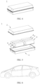
- FIG. 1 shows a rectangular secondary battery 5 as an example.
- the outer package may include a housing 51 and a cover plate 53.
- the housing 51 may include a base plate and a side plate connected onto the base plate, where the base plate and the side plate enclose an accommodating cavity.
- the housing 51 has an opening communicating with the accommodating cavity, and the cover plate 53 can cover the opening to close the accommodating cavity.
- the positive electrode plate, the negative electrode plate, and the separator may be made into an electrode assembly 52 through winding or lamination.
- the electrode assembly 52 is packaged in the accommodating cavity.
- the electrolyte infiltrates the electrode assembly 52.
- the secondary battery 5 may include one or more electrode assemblies 52, and persons skilled in the art may make choices according to actual requirements.
- the secondary battery may be assembled into a battery module, and the battery module may include one or more secondary batteries.
- the specific quantity may be chosen by persons skilled in the art according to use and capacity of the battery module.
- FIG. 3 shows a battery module 4 as an example.
- a plurality of secondary batteries 5 may be sequentially arranged along a length direction of the battery module 4.
- the batteries may alternatively be arranged in any other manners.
- the plurality of secondary batteries 5 may be fixed by fasteners.
- the battery module 4 may further include an enclosure with an accommodating space, and the plurality of secondary batteries 5 are accommodated in the accommodating space.
- the battery module may be further assembled into a battery pack, and the battery pack may include one or more battery modules.
- the specific quantity may be chosen by persons skilled in the art according to use and capacity of the battery pack.
- FIG. 4 and FIG. 5 show a battery pack 1 as an example.
- the battery pack 1 may include a battery box and a plurality of battery modules 4 arranged in the battery box.
- the battery box includes an upper box body 2 and a lower box body 3.
- the upper box body 2 can be engaged with the lower box body 3 to form an enclosed space for accommodating the battery modules 4.
- the plurality of battery modules 4 may be arranged in the battery box in any manner.
- this application further provides an electric apparatus.
- the electric apparatus includes at least one of the secondary battery, the battery module, or the battery pack provided in this application.
- the secondary battery, the battery module, or the battery pack may be used as a power source for the electric apparatus or an energy storage unit of the electric apparatus.
- the electric apparatus may include a mobile device (for example, a mobile phone or a notebook computer), an electric vehicle (for example, a battery electric vehicle, a hybrid electric vehicle, a plug-in hybrid electric vehicle, an electric bicycle, an electric scooter, an electric golf vehicle, or an electric truck), an electric train, a ship, a satellite system, an energy storage system, or the like, but is not limited thereto.
- the secondary battery, the battery module, or the battery pack may be selected for the electric apparatus based on requirements for using the electric apparatus.
- FIG. 6 shows an electric apparatus as an example.
- This electric apparatus is a battery electric vehicle, a hybrid electric vehicle, a plug-in hybrid electric vehicle, or the like.
- a battery pack or a battery module may be used.
- the first solvent is selected from the following solvents:
- the first additive is selected from the following compounds: and
- Preparation of doped lithium manganese phosphate 1 mol of the manganese oxalate particles, 0.497 mol of lithium carbonate, 0.001 mol of Mo(SO 4 ) 3 , an aqueous phosphoric acid solution containing 0.999 mol of phosphoric acid with a concentration of 85%, 0.001 mol of H 4 SiO 4 , 0.0005 mol of NH 4 HF 2 , and 0.005 mol of sucrose were added to 20 L of deionized water. The resulting mixture was transferred to a sand mill and fully ground and stirred for 10 hours to obtain a slurry.
- the slurry was transferred to a spray drying device for spray drying and granulation, with the drying temperature set to 250°C and the drying time set to 4 hours, to obtain particles.
- a protective atmosphere of nitrogen (90vol%) + hydrogen (10vol%) the powder material was sintered at 700°C for 10 hours to obtain Li 0.994 Mo 0.001 Mn 0.65 Fe 0.35 P 0.999 Si 0.001 O 3.999 F 0.001 coated with carbon.
- the proportions of elements in the positive electrode active material could be tested by using inductively coupled plasma atomic emission spectrometry (ICP).
- This example was the same as preparation example 1 except that in "(1) preparation of positive electrode active material", the amount of high-purity Li 2 CO 3 was changed to 0.4885 mol, M O (SO 4 ) 3 was replaced with MgSO 4 , and the amount of FeSO 4 ⁇ H 2 O was changed to 0.68 mol, and that during preparation of doped manganese oxalate, 0.02 mol of Ti(SO 4 ) 2 was also added and H 4 SiO 4 was changed to HNO 3 .
- This example was the same as preparation example 1 except that in "(1) preparation of positive electrode active material", the amount of high-purity Li 2 CO 3 was changed to 0.496 mol, M O (SO 4 ) 3 was replaced with W(SO 4 ) 3 , and H 4 SiO 4 was replaced with H 2 SO 4 .
- This example was the same as preparation example 1 except that in "(1) preparation of positive electrode active material", the amount of high-purity Li 2 CO 3 was changed to 0.4985 mol, 0.001 mol of M O (SO 4 ) 3 was replaced with 0.0005 mol of Al 2 (SO 4 ) 3 , and NH 4 HF 2 was replaced with NH 4 HCl 2 .
- This example was the same as preparation example 1 except that in "(1) preparation of positive electrode active material", the amount of FeSO 4 ⁇ H 2 O was changed from 0.7 mol to 0.69 mol, and that during preparation of doped manganese oxalate, 0.01 mol of VCl 2 was also added, the amount of Li 2 CO 3 was changed to 0.4965 mol, 0.001 mol of M O (SO 4 ) 3 was replaced with 0.0005 mol of Nb 2 (SO 4 ) 5 , and H 4 SiO 4 was replaced with H 2 SO 4 .
- This example was the same as preparation example 1 except that in "(1) preparation of positive electrode active material", the amount of FeSO 4 ⁇ H 2 O was changed to 0.68 mol, and that during preparation of doped manganese oxalate, 0.01 mol of VCl 2 and 0.01mol of MgSO 4 were also added, the amount of Li 2 CO 3 was changed to 0.4965 mol, 0.001 mol of M O (SO 4 ) 3 was replaced with 0.0005 mol of Nb 2 (SO 4 ) 5 , and H 4 SiO 4 was replaced with H 2 SO 4 .
- This example was the same as preparation example 6 except that in "(1) preparation of positive electrode active material", MgSO 4 was replaced with CoSO 4 .
- This example was the same as preparation example 6 except that in "(1) preparation of positive electrode active material", MgSO 4 was replaced with NiSO 4 .
- This example was the same as preparation example 1 except that in "(1) preparation of positive electrode active material", the amount of FeSO 4 ⁇ H 2 O was changed to 0.698 mol, and that during preparation of doped manganese oxalate, 0.002 mol of Ti(SO 4 ) 2 was also added, the amount ofLi 2 CO 3 was changed to 0.4955 mol, 0.001 mol of M O (SO 4 ) 3 was replaced with 0.0005 mol of Nb 2 (SO 4 ) 5 , H 4 SiO 4 was replaced with H 2 SO 4 , and NH 4 HF 2 was replaced with NH 4 HCl 2 .
- This example was the same as preparation example 1 except that in "(1) preparation of positive electrode active material", the amount of FeSO 4 ⁇ H 2 O was changed to 0.68 mol, and that during preparation of doped manganese oxalate, 0.01 mol of VCl 2 and 0.01 mol of MgSO 4 were also added, the amount of Li 2 CO 3 was changed to 0.4975 mol, 0.001 mol of M O (SO 4 ) 3 was replaced with 0.0005 mol of Nb 2 (SO 4 ) 5 , and NH 4 HF 2 was replaced with NH 4 HBr 2 .
- This example was the same as preparation example 1 except that in "(1) preparation of positive electrode active material", the amount of FeSO 4 ⁇ H 2 O was changed to 0.69 mol, and that during preparation of doped manganese oxalate, 0.01 mol of VCl 2 was also added, the amount of Li 2 CO 3 was changed to 0.499 mol, Mo(SO 4 ) 3 was replaced with MgSO 4 , and NH 4 HF 2 was replaced with NH 4 HBr 2 .
- This example was the same as preparation example 1 except that in "(1) preparation of positive electrode active material", the amount of MnSO 4 ⁇ H 2 O was changed to 1.36 mol, and the amount of FeSO 4 ⁇ H 2 O was changed to 0.6 mol, and that during preparation of doped manganese oxalate, 0.04 mol of VCl2 was also added, the amount of Li 2 CO 3 was changed to 0.4985 mol, M O (SO 4 ) 3 was replaced with MgSO 4 , and H 4 SiO 4 was replaced with HNO 3 .
- This example was the same as preparation example 12 except that in "(1) preparation of positive electrode active material", the amount of MnSO 4 ⁇ H 2 O was changed to 1.16 mol, and the amount of FeSO 4 ⁇ H 2 O was changed to 0.8 mol.
- This example was the same as preparation example 12 except that in "(1) preparation of positive electrode active material", the amount of MnSO 4 ⁇ H 2 O was changed to 1.3 mol, and the amount of VCl 2 was changed to 0.1 mol.
- This example was the same as preparation example 1 except that in "(1) preparation of positive electrode active material", the amount of MnSO 4 ⁇ H 2 O was changed to 1.2 mol, and that during preparation of doped manganese oxalate, 0.1 mol of VCl 2 was also added, the amount of Li 2 CO 3 was changed to 0.494 mol, 0.001 mol of M O (SO 4 ) 3 was replaced with 0.005 mol of MgSO 4 , and H 4 SiO 4 was replaced with H 2 SO 4 .
- This example was the same as preparation example 1 except that in "(1) preparation of positive electrode active material", the amount of MnSO 4 ⁇ H 2 O was changed to 1.2 mol, and that during preparation of doped manganese oxalate, 0.1 mol of VCl 2 was also added, the amount of Li 2 CO 3 was changed to 0.467 mol, 0.001 mol of M O (SO 4 ) 3 was replaced with 0.005 mol of MgSO 4 , 0.001 mol of H 4 SiO 4 was replaced with 0.005 mol of H 2 SO 4 , and the amount of phosphoric acid with a concentration of 85% was changed from 1.175 mol to 1.171 mol.
- This example was the same as preparation example 1 except that in "(1) preparation of positive electrode active material", the amount of MnSO 4 ⁇ H 2 O was changed to 1.2 mol, and that during preparation of doped manganese oxalate, 0.1 mol of VCl 2 was also added, the amount of Li 2 CO 3 was changed to 0.492 mol, 0.001 mol of M O (SO 4 ) 3 was replaced with 0.005 mol of MgSO 4 , H 4 SiO 4 was replaced with H 2 SO 4 , and the amount of NH 4 HF 2 was changed from 0.0005 mol to 0.0025 mol.
- This example was the same as preparation example 1 except that in "(1) preparation of positive electrode active material", the amount of FeSO 4 ⁇ H 2 O was changed to 0.5 mol, and that during preparation of doped manganese oxalate, 0.1 mol of VCl 2 and 0.1 mol of CoSO 4 were also added, the amount of Li 2 CO 3 was changed to 0.492 mol, 0.001 mol of M O (SO 4 ) 3 was replaced with 0.005 mol of MgSO 4 , H 4 SiO 4 was replaced with H 2 SO 4 , and the amount of NH 4 HF 2 was changed from 0.0005 mol to 0.0025 mol.
- This example was the same as preparation example 18 except that in "(1) preparation of positive electrode active material", the amount of FeSO 4 ⁇ H 2 O was changed to 0.4 mol, and the amount of CoSO 4 was changed from 0.1 mol to 0.2 mol.
- This example was the same as preparation example 18 except that in "(1) preparation of positive electrode active material", the amount of MnSO 4 ⁇ H 2 O was changed to 1.5 mol, the amount of FeSO 4 ⁇ H 2 O was changed to 0.1 mol, and the amount of CoSO 4 was changed to 0.3 mol.
- This example was the same as preparation example 18 except that in "(1) preparation of positive electrode active material", 0.1 mol of CoSO 4 was replaced with 0.1 mol of NiSO 4 .
- This example was the same as preparation example 18 except that in "(1) preparation of positive electrode active material", the amount of MnSO 4 ⁇ H 2 O was changed to 1.5 mol, the amount of FeSO 4 ⁇ H 2 O was changed to 0.2 mol, and 0.1 mol of CoSO 4 was replaced with 0.2 mol of NiSO 4 .
- This example was the same as preparation example 18 except that in "(1) preparation of positive electrode active material", the amount of MnSO 4 ⁇ H 2 O was changed to 1.4 mol, the amount of FeSO 4 ⁇ H 2 O was changed to 0.3 mol, and the amount of CoSO 4 was changed to 0.2 mol.
- This example was the same as preparation example 1 except that in "(1) preparation of positive electrode active material", the amount of MnSO 4 ⁇ H 2 O was changed from 1.3 mol to 1.2 mol, and the amount of FeSO 4 ⁇ H 2 O was changed from 0.7 mol to 0.5 mol, and that during preparation of doped manganese oxalate, 0.1 mol of VCl 2 and 0.2 mol of CoSO 4 were also added, the amount of Li 2 CO 3 was changed to 0.497 mol, 0.001 mol of Mo(SO 4 ) 3 was replaced with 0.005 mol of MgSO 4 , H 4 SiO 4 was replaced with H 2 SO 4 , and the amount of NH 4 HF 2 was changed from 0.0005 mol to 0.0025 mol.
- This example was the same as preparation example 18 except that in "(1) preparation of positive electrode active material", the amount of MnSO 4 ⁇ H 2 O was changed to 1.0 mol, the amount of FeSO 4 ⁇ H 2 O was changed to 0.7 mol, and the amount of CoSO 4 was changed to 0.2 mol.
- This example was the same as preparation example 1 except that in "(1) preparation of positive electrode active material", the amount of MnSO 4 ⁇ H 2 O was changed to 1.4 mol, and the amount of FeSO 4 ⁇ H 2 O was changed to 0.3 mol, and that during preparation of doped manganese oxalate, 0.1 mol of VCl 2 and 0.2 mol of CoSO 4 were also added, the amount of Li 2 CO 3 was changed to 0.4825 mol, 0.001 mol of M O (SO 4 ) 3 was replaced with 0.005 mol of MgSO 4 , the amount of H 4 SiO 4 was changed to 0.1 mol, the amount of phosphoric acid was changed to 0.9 mol, and the amount of NH 4 HF 2 was changed to 0.04 mol.
- This example was the same as preparation example 1 except that in "(1) preparation of positive electrode active material", the amount of MnSO 4 ⁇ H 2 O was changed to 1.4 mol, the amount of FeSO 4 ⁇ H 2 O was changed to 0.3 mol, and that during preparation of doped manganese oxalate, 0.1 mol of VCl 2 and 0.2 mol of CoSO 4 were also added, the amount of Li 2 CO 3 was changed to 0.485 mol, 0.001 mol of M O (SO 4 ) 3 was replaced with 0.005 mol of MgSO 4 , the amount of H 4 SiO 4 was changed to 0.08 mol, the amount of phosphoric acid was changed to 0.92 mol, and the amount of NH 4 HF 2 was changed to 0.05 mol.
- lithium manganese phosphate 1 mol of the manganese oxalate particles, 0.5 mol of lithium carbonate, an aqueous phosphoric acid solution containing 1 mol of phosphoric acid with a concentration of 85%, and 0.005 mol of sucrose were added to 20 L of deionized water. The resulting mixture was transferred to a sand mill and fully ground and stirred for 10 hours to obtain a slurry. The slurry was transferred to a spray drying device for spray drying and granulation, with the drying temperature set to 250°C and the drying time set to 4 hours, to obtain particles. In a protective atmosphere of nitrogen (90vol%) + hydrogen (10vol%), the powder material was sintered at 700°C for 10 hours to obtain LiMnPO 4 coated with carbon.
- This example was the same as comparative preparation example 1 except that 1 mol of MnSO 4 ⁇ H 2 O in comparative preparation example 1 was replaced with 0.85 mol of MnSO 4 ⁇ H 2 O and 0.15 mol of FeSO 4 ⁇ H 2 O, and these materials were added into a mixer and well mixed for 6 hours and then added into a reactor.
- This example was the same as preparation example 1 except that in "(1) preparation of positive electrode active material", the amount of MnSO 4 ⁇ H 2 O was changed to 1.9 mol, 0.7 mol of FeSO 4 .H 2 O was replaced with 0.1 mol of ZnSO 4 , the amount of Li 2 CO 3 was changed to 0.495 mol, 0.001 mol of M O (SO 4 ) 3 was replaced with 0.005 mol of MgSO 4 , the amount of phosphoric acid was changed to 1 mol, and neither H 4 SiO 4 nor NH 4 HF 2 was added.
- This example was the same as preparation example 1 except that in "(1) preparation of positive electrode active material", the amount of MnSO 4 ⁇ H 2 O was changed to 1.2 mol, the amount of FeSO 4 ⁇ H 2 O was changed to 0.8 mol, the amount of Li 2 CO 3 was changed to 0.45 mol, 0.001 mol of M O (SO 4 ) 3 was replaced with 0.005 mol of Nb 2 (SO 4 ) 5 , the amount of phosphoric acid was changed from 0.999 mol to 1 mol, the amount of NH 4 HF 2 was changed from 0.0005 mol to 0.025 mol, and no H 4 SiO 4 was added.
- This example was the same as preparation example 1 except that in "(1) preparation of positive electrode active material", the amount of MnSO 4 ⁇ H 2 O was changed to 1.4 mol, the amount of FeSO 4 ⁇ H 2 O was changed to 0.6 mol, the amount of Li 2 CO 3 was changed to 0.38 mol, and 0.001 mol of M O (SO 4 ) 3 was replaced with 0.12 mol of MgSO 4 .
- This example was the same as preparation example 1 except that in "(1) preparation of positive electrode active material", the amount of MnSO 4 ⁇ H 2 O was changed to 0.8 mol, 0.7 mol of FeSO 4 ⁇ H 2 O was replaced with 1.2 mol of ZnSO 4 , the amount of Li 2 CO 3 was changed to 0.499 mol, and 0.001 mol of M O (SO 4 ) 3 was replaced with 0.001 mol of MgSO 4 .
- This example was the same as preparation example 1 except that in "(1) preparation of positive electrode active material", the amount of MnSO 4 ⁇ H 2 O was changed to 1.4 mol, the amount of FeSO 4 ⁇ H 2 O was changed to 0.6 mol, the amount of Li 2 CO 3 was changed to 0.534 mol, 0.001 mol of M O (SO 4 ) 3 was replaced with 0.001 mol of MgSO 4 , the amount of phosphoric acid was changed to 0.88 mol, the amount of H 4 SiO 4 was changed to 0.12 mol, and the amount of NH 4 HF 2 was changed to 0.025 mol.
- This example was the same as preparation example 1 except that in "(1) preparation of positive electrode active material", the amount of MnSO 4 ⁇ H 2 O was changed to 1.2 mol, the amount of FeSO 4 ⁇ H 2 O was changed to 0.8 mol, the amount of Li 2 CO 3 was changed to 0.474 mol, 0.001 mol of M O (SO 4 ) 3 was replaced with 0.001 mol of MgSO 4 , the amount of phosphoric acid was changed to 0.93 mol, the amount of H 4 SiO 4 was changed to 0.07 mol, and the amount of NH 4 HF 2 was changed to 0.06 mol.
- the positive electrode active material, polyvinylidene fluoride (PVDF), and acetylene black were added at a weight ratio of 90:5:5 to N-methylpyrrolidone (NMP), and stirred in a drying room to obtain a slurry.
- the slurry was applied onto an aluminum foil, followed by drying and cold pressing to obtain a positive electrode plate.
- the application amount was 0.2 g/cm 2
- the compacted density was 2.0 g/cm 3 .
- a lithium sheet used as a negative electrode, a solution containing ethylene carbonate (EC), diethyl carbonate (DEC), and dimethyl carbonate (DMC) at a volume ratio of 1:1:1 and 1 mol/L LiPF 6 used as an electrolyte, and the prepared positive electrode plate were assembled together in a button cell box to form a button cell (also referred to as "button battery” hereafter), where an injection factor of the button battery was 3.5 g/mAh.
- EC ethylene carbonate
- DEC diethyl carbonate
- DMC dimethyl carbonate
- the positive electrode active material, a conductive agent acetylene black, and a binder polyvinylidene difluoride (PVDF) were well mixed at a weight ratio of 92:2.5:5.5 in an N-methylpyrrolidone solvent system, and then the resulting mixture was applied onto an aluminum foil, followed by drying and cold pressing to obtain a positive electrode plate.
- An application amount was 0.4 g/cm 2
- a compacted density was 2.4 g/cm 3 .
- a negative electrode active material artificial graphite, hard carbon, a conductive agent acetylene black, a binder styrene-butadiene rubber (SBR), and a thickener sodium carboxymethyl cellulose (CMC) were well mixed at a weight ratio of 90:5:2:2:1 in deionized water, and then the resulting mixture was applied onto a copper foil, followed by drying and cold pressing to obtain a negative electrode plate.
- An application amount was 0.2 g/cm 2
- a compacted density was 1.7 g/cm'.
- a polyethylene (PE) porous polymeric film was used as a separator; the positive electrode plate, the separator, and the negative electrode plate were stacked in sequence, so that the separator was located between the positive electrode plate and the negative electrode plate for separation; and the resulting stack was wound to obtain a bare cell.
- the bare cell was placed in an outer package, an electrolyte that was the same as the electrolyte used during preparation of the button battery was injected, and the outer package was sealed to obtain a full cell (also referred to as "full battery” hereinafter), where an injection factor of the full battery was 3.5 g/mAh.
- the positive electrode active material samples were placed in an XRD instrument (model: Bruker D8 Discover), and the samples were tested at 1°/min.
- the test data were organized and analyzed, and the lattice constants a0, b0, c0, and v0 (where a0, b0, and c0 represented the lengths of faces of the unit cell, and v0 denoted the volume of the unit cell, which could be obtained directly from XRD refinement results) at that time point were calculated with reference to the standard PDF card.
- the positive electrode active material samples were prepared into button batteries using the preparation method of button battery in the foregoing example, and the button batteries were charged at a small rate of 0.05C until the current was reduced to 0.01C.
- the positive electrode plate was then taken out from the button battery and placed in DMC for 8 hours, then dried, and scraped for powder, and particles with a particle size less than 500 nm were sifted out from the powder.
- Samples were taken and subjected to the same way as the fresh samples under test above to calculate their lattice constants v1, and (v0-v1)/v0 ⁇ 100% was taken as their lattice change rates before and after complete deintercalation or intercalation of lithium to be listed in the table.
- the XRD results tested in "test method for lattice change rate” were compared with the PDF (Powder Diffraction File) card of the standard crystal to obtain the Li/Mn antisite defect concentration.
- the XRD results tested in "test method for lattice change rate” were imported into the general structural analysis system (GSAS) software to automatically derive the refinement results, which contained the occupancy of the different atoms, and then the Li/Mn antisite defect concentration was obtained by reading the refinement results.
- GSAS general structural analysis system
- the positive electrode active material sample was taken to prepare into a button battery according to the preparation method of button battery in the foregoing example.
- the button battery was charged at a small rate of 0.05C until the current was reduced to 0.01C.
- the positive electrode plate was then taken out from the button battery and placed in DMC for 8 hours, then dried, and scraped for powder, and particles with a particle size less than 500 nm were sifted out from the powder.
- the obtained particles were measured using electron energy loss spectroscopy (EELS; the model of the instrument used was Talos F200S) to obtain energy loss near edge structures (ELNES) that reflected the density of states and energy level distribution of elements. Based on the density of states and energy level distribution, the number of occupying electrons was calculated by integrating the data of the valence band density of states to deduce the surface oxygen valence after charging.
- the button battery was charged to 4.3 V at 0.1C under a voltage of 2.5 V to 4.3 V, then constant-voltage charged at 4.3 V to a current less than or equal to 0.05 mA, left standing for 5 min, and then discharged to 2.0 V at 0.1C, and a discharge capacity at that time point was an initial gram capacity and recorded as D0.
- the full batteries were charged to 4.3 V at 1C under a voltage of 2.5 V to 4.3 V, and then constant-voltage charged at 4.3 V to a current less than or equal to 0.05 mA.
- the full batteries were left standing for 5 min and then discharged to 2.5 V at 1C, and a discharge capacity at that time point was recorded as D0.
- the charge and discharge cycle was repeated until the discharge capacity was reduced to 80% of D0. The number of cycles the battery had undergone at that time point was recorded.
- the full batteries at 100% state of charge (SOC) were stored at 60°C.
- the open circuit voltage (OCV) and alternating current internal resistance (IMP) of the cells were measured before, during, and after storage to monitor the SOCs, and the volumes of the cells were measured.
- the full batteries were taken out after every 48 h of storage and left standing for 1 h. Then the open circuit voltage (OCV) and internal resistance (IMP) were tested, and the cell volumes were tested in a drainage method after the batteries were cooled to room temperature.
- Positive electrode active material compositions in comparative preparation examples 1 to 8 and preparation examples 1 to 11 are given in Table 1. Performance data of the positive electrode active materials in comparative preparation examples 1 to 8 and preparation examples 1 to 11, or of button batteries or full batteries prepared using corresponding positive electrode active materials as positive electrode active materials of batteries, sequentially named as comparative example 1, comparative example 2, comparative example 3, ..., and comparative example 19, measured in the foregoing performance test methods are given in Table 2. Positive electrode active material compositions in preparation examples 12 to 27 are given in Table 3.
- Performance data of the positive electrode active materials in preparation examples 12 to 27, or of button batteries or full batteries prepared using corresponding positive electrode active materials as positive electrode active materials of batteries, sequentially named as comparative example 20, comparative example 21, comparative example 22, ..., and comparative example 35, measured in the foregoing performance test methods are given in Table 4.
- the electrolytes in comparative examples 1 to 35 were replaced with the following electrolyte, and then these examples were sequentially used as comparative examples 36 to 43 (that was, the electrolytes in comparative examples 1 to 8 were correspondingly replaced) and examples 1 to 27 (that was, the electrolytes in comparative examples 9 to 35 were correspondingly replaced).
- Solvent 1 was used as the first solvent, ethylene carbonate (EC), diethyl carbonate (DEC), and dimethyl carbonate (DMC) at a volume ratio of 1:1:1 formed the second solvent, and the first solvent and the second solvent were used as solvents for the electrolyte, where a mass ratio of the first solvent to the second solvent was 1:1; LiPF 6 was used as a lithium salt in the electrolyte with a concentration of 1 mol/L; and additive 1 was as the first additive of the electrolyte with a mass percentage in the electrolyte of 3%.
- EC ethylene carbonate
- DEC diethyl carbonate
- DMC dimethyl carbonate
- composition of the electrolyte in example 21 was sequentially replaced with the compositions of the electrolytes shown in Table 6 to form examples 28 to 61.
- the second solvents in the electrolytes were all formed by ethylene carbonate (EC), diethyl carbonate (DEC), and dimethyl carbonate (DMC) at a volume ratio of 1:1:1, with specific amounts shown in Table 6.
- the percentage of the first additive referred to the mass percentage of the first additive with respect to the electrolyte, and the mass percentages of the first solvent and the second solvent were based on the sum of the masses of the first solvent and the second solvent.
- Table 8 shows the types of additives and the percentages of the additives in the electrolyte.
- the initial gram capacity of button battery (mAh/g), 3C constant current charge ratio (%), number of cycles at 80% capacity retention rate at 45°C, and cell swelling rate after storage at 60°C (%) were tested in the foregoing methods, and the test results were recorded in Table 8.
Landscapes
- Chemical & Material Sciences (AREA)
- General Chemical & Material Sciences (AREA)
- Chemical Kinetics & Catalysis (AREA)
- Electrochemistry (AREA)
- Inorganic Chemistry (AREA)
- Engineering & Computer Science (AREA)
- Manufacturing & Machinery (AREA)
- General Physics & Mathematics (AREA)
- Condensed Matter Physics & Semiconductors (AREA)
- Physics & Mathematics (AREA)
- Composite Materials (AREA)
- Crystallography & Structural Chemistry (AREA)
- Materials Engineering (AREA)
- Secondary Cells (AREA)
- Battery Electrode And Active Subsutance (AREA)
Applications Claiming Priority (1)
| Application Number | Priority Date | Filing Date | Title |
|---|---|---|---|
| PCT/CN2022/090396 WO2023206397A1 (zh) | 2022-04-29 | 2022-04-29 | 二次电池、电池模块、电池包和用电装置 |
Publications (2)
| Publication Number | Publication Date |
|---|---|
| EP4407732A1 true EP4407732A1 (de) | 2024-07-31 |
| EP4407732A4 EP4407732A4 (de) | 2025-04-16 |
Family
ID=88516891
Family Applications (1)
| Application Number | Title | Priority Date | Filing Date |
|---|---|---|---|
| EP22939246.9A Pending EP4407732A4 (de) | 2022-04-29 | 2022-04-29 | Sekundärbatterie, batteriemodul, batteriepack und elektrische vorrichtung |
Country Status (4)
| Country | Link |
|---|---|
| US (1) | US20240387813A1 (de) |
| EP (1) | EP4407732A4 (de) |
| CN (1) | CN117203809A (de) |
| WO (1) | WO2023206397A1 (de) |
Families Citing this family (5)
| Publication number | Priority date | Publication date | Assignee | Title |
|---|---|---|---|---|
| US20240396089A1 (en) * | 2023-05-22 | 2024-11-28 | Uchicago Argonne, Llc | Non-Aqueous Fluorinated Electrolytes for Lithium Batteries |
| CN117219868B (zh) * | 2023-11-09 | 2024-04-09 | 宁德时代新能源科技股份有限公司 | 电解液、钠二次电池和用电装置 |
| CN120978193A (zh) * | 2024-05-17 | 2025-11-18 | 宁德时代新能源科技股份有限公司 | 二次电池以及用电设备 |
| JP7810246B1 (ja) * | 2024-12-25 | 2026-02-03 | トヨタ自動車株式会社 | 正極活物質、電極および電池 |
| CN121215907A (zh) * | 2025-11-26 | 2025-12-26 | 华南理工大学 | 一种非水电解液及锂离子电池 |
Family Cites Families (9)
| Publication number | Priority date | Publication date | Assignee | Title |
|---|---|---|---|---|
| US20030190527A1 (en) * | 2002-04-03 | 2003-10-09 | James Pugh | Batteries comprising alkali-transition metal phosphates and preferred electrolytes |
| CN101339994B (zh) * | 2008-09-01 | 2010-12-01 | 甘肃大象能源科技有限公司 | 多位掺杂型磷酸铁锂正极材料制备方法及其应用 |
| CN103069624B (zh) * | 2010-07-01 | 2016-06-22 | 夏普株式会社 | 正极活性材料、正极和非水二次电池 |
| CN103346295B (zh) * | 2013-07-11 | 2016-06-15 | 宁波晟腾新材料有限公司 | 一种多元素掺杂磷酸铁锂复合正极材料的制备方法 |
| KR101764266B1 (ko) * | 2014-12-02 | 2017-08-04 | 주식회사 엘지화학 | 저온 성능이 향상된 리튬 이차전지용 전해액 및 이를 포함하는 리튬 이차전지 |
| CN104577115A (zh) * | 2014-12-26 | 2015-04-29 | 青海时代新能源科技有限公司 | 一种锂离子电池正极材料、其制备方法及应用 |
| CN114256448A (zh) * | 2020-09-25 | 2022-03-29 | 比亚迪股份有限公司 | 磷酸锰铁锂复合材料及其制备方法和锂离子电池 |
| EP4485576A4 (de) * | 2022-04-01 | 2025-03-19 | Contemporary Amperex Technology Co., Limited | Sekundärbatterie, batteriemodul, batteriepack und elektrische vorrichtung |
| JP7693009B2 (ja) * | 2022-04-01 | 2025-06-16 | 香港時代新能源科技有限公司 | 二次電池、電池モジュール、電池パックおよび電気装置 |
-
2022
- 2022-04-29 WO PCT/CN2022/090396 patent/WO2023206397A1/zh not_active Ceased
- 2022-04-29 EP EP22939246.9A patent/EP4407732A4/de active Pending
- 2022-04-29 CN CN202280012860.XA patent/CN117203809A/zh active Pending
-
2024
- 2024-07-17 US US18/775,409 patent/US20240387813A1/en active Pending
Also Published As
| Publication number | Publication date |
|---|---|
| CN117203809A (zh) | 2023-12-08 |
| US20240387813A1 (en) | 2024-11-21 |
| EP4407732A4 (de) | 2025-04-16 |
| WO2023206397A1 (zh) | 2023-11-02 |
Similar Documents
| Publication | Publication Date | Title |
|---|---|---|
| EP4407732A1 (de) | Sekundärbatterie, batteriemodul, batteriepack und elektrische vorrichtung | |
| EP4485576A1 (de) | Sekundärbatterie, batteriemodul, batteriepack und elektrische vorrichtung | |
| EP4546454A1 (de) | Positivelektrodenaktivmaterial, herstellungsverfahren für positivelektrodenaktivmaterial, positivelektrodenplatte, sekundärbatterie, batteriemodul, batteriepack und elektrische vorrichtung | |
| EP4280300A1 (de) | Positivelektrodenaktivmaterial, herstellungsverfahren dafür und positivelektrodenplatte, sekundärbatterie und elektrische vorrichtung damit | |
| EP4394938A1 (de) | Positivelektrodenaktivmaterial, herstellungsverfahren dafür, positivelektrodenfolie, sekundärbatterie, batteriemodul, batteriepack und elektrische vorrichtung | |
| US20250062415A1 (en) | Secondary battery, battery module, battery pack, and electric apparatus | |
| EP4293777A1 (de) | Sekundärbatterie, batteriemodul, batteriepack und elektrische vorrichtung | |
| JP2024526829A (ja) | 正極活物質、その製造方法、それを含むリチウムイオン電池、電池モジュール、電池パックと電力消費装置 | |
| US12548772B2 (en) | Positive electrode sheet, secondary battery, battery module, battery pack and electrical apparatus | |
| US20260024762A1 (en) | Negative electrode plate, secondary battery, and electric apparatus | |
| EP4336593B1 (de) | Positivelektrodenaktivmaterial, herstellungsverfahren dafür und positivelektrodenplatte damit | |
| EP4386898B1 (de) | Sekundärbatterie, batteriemodul, batteriepack und elektrische vorrichtung | |
| EP4546460A1 (de) | Sekundärbatterie, batteriemodul, batteriepack und elektrische vorrichtung | |
| US20250286138A1 (en) | Nonaqueous electrolyte solution, lithium secondary battery containing same, and electrical device | |
| EP4329031A1 (de) | Sekundärbatterie, batteriemodul, batteriepack und elektrische vorrichtung | |
| EP4682979A1 (de) | Verfahren zur herstellung eines positivelektrodenmaterials, positivelektrodenmaterial, positivelektrodenfolie, batterie und elektrische vorrichtung | |
| EP4322254A1 (de) | Positivelektrodenaktivmaterial mit kern-schale-struktur und herstellungsverfahren dafür, positivelektrodenplatte, sekundärbatterie, batteriemodul, batteriepack und elektrische vorrichtung | |
| EP4468406A1 (de) | Sekundärbatterie, batteriemodul, batteriepack und elektrische vorrichtung | |
| EP4379838A1 (de) | Sekundärbatterie und batteriemodul, batteriepack und elektrische vorrichtung damit | |
| EP4629313A1 (de) | Negativelektrodenfolie, sekundärbatterie und elektrische vorrichtung | |
| EP4293746A1 (de) | Positivelektrodenaktivmaterial und herstellungsverfahren dafür, positivelektrodenplatte damit, sekundärbatterie und elektrische vorrichtung | |
| KR102956958B1 (ko) | 정극 재료 조성물, 이를 제조하는 방법 및 이를 포함하는 정극 시트, 이차 전지 및 전기 장치 | |
| EP4318704A1 (de) | Sekundärbatterie, batteriemodul, batteriepack und elektrische vorrichtung | |
| KR20240108495A (ko) | 정극 재료 조성물, 이를 제조하는 방법 및 이를 포함하는 정극 시트, 이차 전지 및 전기 장치 | |
| CN121282364A (zh) | 一种循环存储性能改善的二次电池和用电装置 |
Legal Events
| Date | Code | Title | Description |
|---|---|---|---|
| STAA | Information on the status of an ep patent application or granted ep patent |
Free format text: STATUS: THE INTERNATIONAL PUBLICATION HAS BEEN MADE |
|
| PUAI | Public reference made under article 153(3) epc to a published international application that has entered the european phase |
Free format text: ORIGINAL CODE: 0009012 |
|
| STAA | Information on the status of an ep patent application or granted ep patent |
Free format text: STATUS: REQUEST FOR EXAMINATION WAS MADE |
|
| 17P | Request for examination filed |
Effective date: 20240425 |
|
| AK | Designated contracting states |
Kind code of ref document: A1 Designated state(s): AL AT BE BG CH CY CZ DE DK EE ES FI FR GB GR HR HU IE IS IT LI LT LU LV MC MK MT NL NO PL PT RO RS SE SI SK SM TR |
|
| RAP1 | Party data changed (applicant data changed or rights of an application transferred) |
Owner name: CONTEMPORARY AMPEREX TECHNOLOGY(HONG KONG) LIMITED |
|
| A4 | Supplementary search report drawn up and despatched |
Effective date: 20250318 |
|
| RIC1 | Information provided on ipc code assigned before grant |
Ipc: H01M 10/0567 20100101ALI20250312BHEP Ipc: H01M 4/58 20100101ALI20250312BHEP Ipc: H01M 4/525 20100101ALI20250312BHEP Ipc: H01M 4/505 20100101ALI20250312BHEP Ipc: H01M 10/0569 20100101ALI20250312BHEP Ipc: H01M 10/0525 20100101AFI20250312BHEP |
|
| DAV | Request for validation of the european patent (deleted) | ||
| DAX | Request for extension of the european patent (deleted) |