EP4407810A1 - Connecteur électrique à verrouillage secondaire à actionnement radial, et système de connexion électrique - Google Patents
Connecteur électrique à verrouillage secondaire à actionnement radial, et système de connexion électrique Download PDFInfo
- Publication number
- EP4407810A1 EP4407810A1 EP23217978.8A EP23217978A EP4407810A1 EP 4407810 A1 EP4407810 A1 EP 4407810A1 EP 23217978 A EP23217978 A EP 23217978A EP 4407810 A1 EP4407810 A1 EP 4407810A1
- Authority
- EP
- European Patent Office
- Prior art keywords
- locking element
- contact carrier
- secondary locking
- connector
- contact
- Prior art date
- Legal status (The legal status is an assumption and is not a legal conclusion. Google has not performed a legal analysis and makes no representation as to the accuracy of the status listed.)
- Pending
Links
Images




Classifications
-
- H—ELECTRICITY
- H01—ELECTRIC ELEMENTS
- H01R—ELECTRICALLY-CONDUCTIVE CONNECTIONS; STRUCTURAL ASSOCIATIONS OF A PLURALITY OF MUTUALLY-INSULATED ELECTRICAL CONNECTING ELEMENTS; COUPLING DEVICES; CURRENT COLLECTORS
- H01R13/00—Details of coupling devices of the kinds covered by groups H01R12/70 or H01R24/00 - H01R33/00
- H01R13/40—Securing contact members in or to a base or case; Insulating of contact members
- H01R13/42—Securing in a demountable manner
- H01R13/436—Securing a plurality of contact members by one locking piece or operation
- H01R13/4364—Insertion of locking piece from the front
- H01R13/4365—Insertion of locking piece from the front comprising a temporary and a final locking position
-
- H—ELECTRICITY
- H01—ELECTRIC ELEMENTS
- H01R—ELECTRICALLY-CONDUCTIVE CONNECTIONS; STRUCTURAL ASSOCIATIONS OF A PLURALITY OF MUTUALLY-INSULATED ELECTRICAL CONNECTING ELEMENTS; COUPLING DEVICES; CURRENT COLLECTORS
- H01R13/00—Details of coupling devices of the kinds covered by groups H01R12/70 or H01R24/00 - H01R33/00
- H01R13/62—Means for facilitating engagement or disengagement of coupling parts or for holding them in engagement
- H01R13/629—Additional means for facilitating engagement or disengagement of coupling parts, e.g. aligning or guiding means, levers, gas pressure electrical locking indicators, manufacturing tolerances
- H01R13/62905—Additional means for facilitating engagement or disengagement of coupling parts, e.g. aligning or guiding means, levers, gas pressure electrical locking indicators, manufacturing tolerances comprising a camming member
- H01R13/62927—Comprising supplementary or additional locking means
-
- H—ELECTRICITY
- H01—ELECTRIC ELEMENTS
- H01R—ELECTRICALLY-CONDUCTIVE CONNECTIONS; STRUCTURAL ASSOCIATIONS OF A PLURALITY OF MUTUALLY-INSULATED ELECTRICAL CONNECTING ELEMENTS; COUPLING DEVICES; CURRENT COLLECTORS
- H01R13/00—Details of coupling devices of the kinds covered by groups H01R12/70 or H01R24/00 - H01R33/00
- H01R13/40—Securing contact members in or to a base or case; Insulating of contact members
- H01R13/42—Securing in a demountable manner
- H01R13/436—Securing a plurality of contact members by one locking piece or operation
- H01R13/4361—Insertion of locking piece perpendicular to direction of contact insertion
- H01R13/4362—Insertion of locking piece perpendicular to direction of contact insertion comprising a temporary and a final locking position
-
- H—ELECTRICITY
- H01—ELECTRIC ELEMENTS
- H01R—ELECTRICALLY-CONDUCTIVE CONNECTIONS; STRUCTURAL ASSOCIATIONS OF A PLURALITY OF MUTUALLY-INSULATED ELECTRICAL CONNECTING ELEMENTS; COUPLING DEVICES; CURRENT COLLECTORS
- H01R13/00—Details of coupling devices of the kinds covered by groups H01R12/70 or H01R24/00 - H01R33/00
- H01R13/02—Contact members
- H01R13/15—Pins, blades or sockets having separate spring member for producing or increasing contact pressure
- H01R13/187—Pins, blades or sockets having separate spring member for producing or increasing contact pressure with spring member in the socket
-
- H—ELECTRICITY
- H01—ELECTRIC ELEMENTS
- H01R—ELECTRICALLY-CONDUCTIVE CONNECTIONS; STRUCTURAL ASSOCIATIONS OF A PLURALITY OF MUTUALLY-INSULATED ELECTRICAL CONNECTING ELEMENTS; COUPLING DEVICES; CURRENT COLLECTORS
- H01R13/00—Details of coupling devices of the kinds covered by groups H01R12/70 or H01R24/00 - H01R33/00
- H01R13/02—Contact members
- H01R13/22—Contacts for co-operating by abutting
- H01R13/24—Contacts for co-operating by abutting resilient; resiliently-mounted
- H01R13/2407—Contacts for co-operating by abutting resilient; resiliently-mounted characterized by the resilient means
- H01R13/2414—Contacts for co-operating by abutting resilient; resiliently-mounted characterized by the resilient means conductive elastomers
-
- H—ELECTRICITY
- H01—ELECTRIC ELEMENTS
- H01R—ELECTRICALLY-CONDUCTIVE CONNECTIONS; STRUCTURAL ASSOCIATIONS OF A PLURALITY OF MUTUALLY-INSULATED ELECTRICAL CONNECTING ELEMENTS; COUPLING DEVICES; CURRENT COLLECTORS
- H01R13/00—Details of coupling devices of the kinds covered by groups H01R12/70 or H01R24/00 - H01R33/00
- H01R13/40—Securing contact members in or to a base or case; Insulating of contact members
- H01R13/42—Securing in a demountable manner
- H01R13/422—Securing in resilient one-piece base or case, e.g. by friction; One-piece base or case formed with resilient locking means
- H01R13/4223—Securing in resilient one-piece base or case, e.g. by friction; One-piece base or case formed with resilient locking means comprising integral flexible contact retaining fingers
-
- H—ELECTRICITY
- H01—ELECTRIC ELEMENTS
- H01R—ELECTRICALLY-CONDUCTIVE CONNECTIONS; STRUCTURAL ASSOCIATIONS OF A PLURALITY OF MUTUALLY-INSULATED ELECTRICAL CONNECTING ELEMENTS; COUPLING DEVICES; CURRENT COLLECTORS
- H01R13/00—Details of coupling devices of the kinds covered by groups H01R12/70 or H01R24/00 - H01R33/00
- H01R13/46—Bases; Cases
- H01R13/502—Bases; Cases composed of different pieces
- H01R13/508—Bases; Cases composed of different pieces assembled by a separate clip or spring
-
- H—ELECTRICITY
- H01—ELECTRIC ELEMENTS
- H01R—ELECTRICALLY-CONDUCTIVE CONNECTIONS; STRUCTURAL ASSOCIATIONS OF A PLURALITY OF MUTUALLY-INSULATED ELECTRICAL CONNECTING ELEMENTS; COUPLING DEVICES; CURRENT COLLECTORS
- H01R13/00—Details of coupling devices of the kinds covered by groups H01R12/70 or H01R24/00 - H01R33/00
- H01R13/46—Bases; Cases
- H01R13/52—Dustproof, splashproof, drip-proof, waterproof, or flameproof cases
- H01R13/5219—Sealing means between coupling parts, e.g. interfacial seal
- H01R13/5221—Sealing means between coupling parts, e.g. interfacial seal having cable sealing means
-
- H—ELECTRICITY
- H01—ELECTRIC ELEMENTS
- H01R—ELECTRICALLY-CONDUCTIVE CONNECTIONS; STRUCTURAL ASSOCIATIONS OF A PLURALITY OF MUTUALLY-INSULATED ELECTRICAL CONNECTING ELEMENTS; COUPLING DEVICES; CURRENT COLLECTORS
- H01R13/00—Details of coupling devices of the kinds covered by groups H01R12/70 or H01R24/00 - H01R33/00
- H01R13/62—Means for facilitating engagement or disengagement of coupling parts or for holding them in engagement
- H01R13/627—Snap or like fastening
- H01R13/6271—Latching means integral with the housing
- H01R13/6273—Latching means integral with the housing comprising two latching arms
-
- H—ELECTRICITY
- H01—ELECTRIC ELEMENTS
- H01R—ELECTRICALLY-CONDUCTIVE CONNECTIONS; STRUCTURAL ASSOCIATIONS OF A PLURALITY OF MUTUALLY-INSULATED ELECTRICAL CONNECTING ELEMENTS; COUPLING DEVICES; CURRENT COLLECTORS
- H01R13/00—Details of coupling devices of the kinds covered by groups H01R12/70 or H01R24/00 - H01R33/00
- H01R13/62—Means for facilitating engagement or disengagement of coupling parts or for holding them in engagement
- H01R13/639—Additional means for holding or locking coupling parts together, after engagement, e.g. separate keylock, retainer strap
-
- H—ELECTRICITY
- H01—ELECTRIC ELEMENTS
- H01R—ELECTRICALLY-CONDUCTIVE CONNECTIONS; STRUCTURAL ASSOCIATIONS OF A PLURALITY OF MUTUALLY-INSULATED ELECTRICAL CONNECTING ELEMENTS; COUPLING DEVICES; CURRENT COLLECTORS
- H01R24/00—Two-part coupling devices, or either of their cooperating parts, characterised by their overall structure
- H01R24/38—Two-part coupling devices, or either of their cooperating parts, characterised by their overall structure having concentrically or coaxially arranged contacts
-
- H—ELECTRICITY
- H01—ELECTRIC ELEMENTS
- H01R—ELECTRICALLY-CONDUCTIVE CONNECTIONS; STRUCTURAL ASSOCIATIONS OF A PLURALITY OF MUTUALLY-INSULATED ELECTRICAL CONNECTING ELEMENTS; COUPLING DEVICES; CURRENT COLLECTORS
- H01R2101/00—One pole
-
- H—ELECTRICITY
- H01—ELECTRIC ELEMENTS
- H01R—ELECTRICALLY-CONDUCTIVE CONNECTIONS; STRUCTURAL ASSOCIATIONS OF A PLURALITY OF MUTUALLY-INSULATED ELECTRICAL CONNECTING ELEMENTS; COUPLING DEVICES; CURRENT COLLECTORS
- H01R2201/00—Connectors or connections adapted for particular applications
- H01R2201/26—Connectors or connections adapted for particular applications for vehicles
Definitions
- the present invention relates to an electrical connector. Furthermore, the invention relates to a corresponding connector system.
- An electrical plug connection system such as is used for establishing electrical connections in a motor vehicle, can comprise a first plug connector and a second plug connector acting as a mating plug connector, each with a primary locking function and a secondary locking function, which ensure that respective plug contacts at the ends of cables to be connected to one another are held securely and in particular with tensile strength in the respective plug connector.
- the locking functions can also be designed in such a way that the plug connector and the mating plug connector can only be fully joined together if the plug contacts have been correctly positioned in the plug connector or the mating plug connector.
- Components for implementing the secondary locking function can vary greatly depending on the housing shape of the plug connector or the mating plug connector.
- EP 3 713 018 A1 describes a connector with a secondary lock which is located in an initial position in an insertion path of the mating connector, wherein the secondary lock can be moved towards a rear end of a connector housing into a locking position such that the secondary lock in the locking position releases the insertion path for the mating connector.
- a first aspect of the invention relates to an electrical connector having a plug contact at one end of a cable, a contact carrier, a plug housing, a primary locking element and a secondary locking element.
- the plug contact is accommodated in the contact carrier.
- the contact carrier is accommodated in the plug housing.
- Both the primary locking element and the secondary locking element are each configured to fix the plug contact in the contact carrier against removal from the contact carrier by pulling in a direction parallel to a longitudinal direction of the cable.
- the secondary locking element is designed as a separate component that can be displaced relative to the contact carrier.
- the secondary locking element, the contact carrier and the plug contact are configured such that the secondary locking element can be brought from a pre-fixed intermediate position to a fixed end position by displacement in a radially inward direction relative to the contact carrier.
- the secondary locking element is held reversibly detachably on the contact carrier in the pre-fixed intermediate position. Furthermore, the secondary locking element is held firmly on the contact carrier in the fixed end position and rests at least partially on the plug contact in such a way that the plug contact in the contact carrier is fixed by the secondary locking element against removal from the contact carrier by pulling in a direction parallel to a longitudinal direction of the cable.
- a second aspect of the invention relates to a plug connection system, comprising a first connector designed as a plug according to an embodiment of the first aspect of the invention and a second connector designed as a socket according to an embodiment of the first aspect of the invention.
- the plug contact of the first connector is electrically connected to the plug contact of the second connector.
- the plug housing of the first connector is mechanically connected to the plug housing of the second connector so that it can withstand at least tensile stress.
- An electrical connector is intended to be connected to another electrical connector, which can also be referred to as a mating connector, in order to bring the cables contained in the two connectors into electrical contact with one another.
- the two connectors thus form a plug connection system.
- One of the connectors can be designed as a plug, i.e. as a male connector, whereas the other connector is designed as a socket, i.e. as a female connector.
- the connector is constructed in several parts and has at least one plug contact, a contact carrier, a plug housing, a primary locking element and a secondary locking element.
- the plug contact is attached to one end of the cable that is to be connected to the cable of a mating connector.
- the cable is generally stripped at its end and is in electrical contact with the plug contact.
- the plug contact usually surrounds the end of the cable and in turn forms contact surfaces via which it can come into electrical contact with contact surfaces of a plug contact of the mating connector.
- the geometry of the plug contact is also adapted to the respective function of the connector.
- the plug contact designed as a plug is also referred to as a male plug contact or "male insert”, whereas the plug contact designed as a socket is sometimes referred to as a female plug contact or "female insert".
- the plug contact generally consists of or comprises an electrically conductive material such as a metal in particular. In particular, the plug contact can be formed with a suitably punched and/or bent metal sheet.
- the contact carrier is used to accommodate the plug contact and hold it reliably. To do this, the contact carrier completely or at least partially surrounds the plug contact when the connector is assembled. When assembling the connector, the plug contact is usually pushed into a recess in the contact carrier in an insertion direction that usually corresponds to a longitudinal direction of the cable.
- the contact carrier generally consists of or comprises an electrically insulating material such as a plastic.
- the contact carrier can be designed as an injection-molded plastic component.
- the connector housing is intended to accommodate the contact carrier together with the connector contact arranged therein and to hold it reliably.
- the connector housing When the connector is assembled, the connector housing generally surrounds the contact carrier completely or at least partially. Dimensions of the connector housing, in particular dimensions in a cross-sectional direction, are usually significantly larger than those of the contact carrier and the connector contact.
- the connector housing is designed to be mechanically connected to a connector housing of the mating connector and to ensure that the connector contacts of the two connectors come into mechanical and electrical contact.
- the connector housing preferably consists of or comprises an electrically insulating material such as a plastic, but can also consist of or comprise other materials.
- the connector housing can be designed as an injection-molded plastic component.
- the primary locking element serves to fix the plug contact inserted into the contact carrier relative to the contact carrier.
- the primary locking element is intended to prevent the plug contact from being moved out of the contact carrier as a result of a force that acts on the plug contact as a pull in an axial direction, i.e. parallel to the longitudinal direction of the cable and preferably against the insertion direction.
- the primary locking element creates a mechanically resilient interaction between the plug contact and the contact carrier.
- the primary locking element can be part of the contact carrier, part of the plug contact or both, or can be provided as a separate component.
- the secondary locking element also serves to fix the plug contact inserted into the contact carrier relative to the contact carrier.
- the secondary locking element thus supports the effect of the primary locking element.
- the Secondary locking element can be configured to act directly on the primary locking element to assist its locking action.
- the secondary locking element can be configured to prevent the primary locking element from being able to move out of a locking position.
- the secondary locking element can interact directly with both the plug contact and the contact carrier to prevent these two components from moving relative to each other.
- the secondary locking element can provide a supplementary locking action without interacting with the primary locking element, so that it can also be regarded as a second primary locking element.
- the secondary locking element of the connector described herein is preferably designed according to the last-described alternative.
- the secondary locking element is configured in a special manner, that is to say designed and/or arranged, wherein the contact carrier and the plug contact of the connector are also configured in an adapted manner for a corresponding interaction with the secondary locking element.
- the secondary locking element is designed as a separate component that can be moved relative to the contact carrier.
- the secondary locking element is intended to be provided as an independent component that can be manufactured and handled independently of the other components of the connector and that can then be installed on the contact carrier when assembling the connector and, in interaction with the plug contact, can ensure the desired secondary locking.
- the secondary locking element, the contact carrier and the plug contact are further specifically configured such that the secondary locking element can be moved relative to the contact carrier between an intermediate position and an end position.
- the configuration of the components is specifically adapted so that the secondary locking element can be displaced from the intermediate position to the end position essentially (i.e., for example, within an angular range of +/- 20° or preferably +/- 10°) or preferably exclusively in a radially inward direction, i.e. in a direction transverse or preferably perpendicular to the longitudinal direction of the cable and towards a center of the contact carrier.
- the secondary locking element In the intermediate position, the secondary locking element is in a pre-fixed state in which it can be reversibly detachably attached to the contact carrier. is held.
- the secondary locking element when it is in the intermediate position, can be fixed to the contact carrier by a frictional connection or a reversibly releasable form-fitting connection.
- the secondary locking element can be pre-latched in the pre-fixed state.
- the secondary locking element In the end position, however, the secondary locking element is in a fixed state in which it is firmly held to the contact carrier, i.e. it cannot be released from the contact carrier reversibly or without damage.
- the secondary locking element can be latched to the contact carrier in the fixed state.
- the secondary locking element is designed and, when it is in the end position, positioned in such a way that it rests mechanically on the plug contact at least in some areas and, through this mechanical contact, secures or locks the plug contact against removal from the contact carrier.
- the secondary locking element is provided as a separate component and, on the other hand, is specially configured to be displaced in cooperation with the contact carrier and the plug contact, preferably only in the radially inward direction, in order to bring it from the pre-fixed intermediate position into the fixed end position.
- the secondary locking element can be easily manufactured and equipped with a geometry required for the desired configuration.
- the secondary locking function can be activated in a particularly simple manner, for example by first provisionally attaching the secondary locking element to the contact carrier in its pre-fixed intermediate position and then simply pressing the secondary locking element transversely to the contact carrier, i.e. in the radially inward direction, into the fixed end position, in order to activate the secondary locking function.
- the secondary locking element is designed as a one-piece molded part.
- Such a one-piece molded part can be designed as an integral component, which is configured, for example, in terms of its geometry in such a way that different sub-areas are formed thereon for implementing different functionalities. It can be easily manufactured, handled and/or installed on the contact carrier.
- the molded part can be made of plastic. It can be manufactured, for example, by means of injection molding.
- the molded part can also be formed with other materials such as a metal or a ceramic. It can optionally be surrounded, in particular overmolded, with another material, in particular a plastic.
- the secondary locking element has a locking section in the form of a rib extending in the radially inward direction.
- the secondary locking element, the contact carrier and the plug contact are configured such that the locking section of the secondary locking element in the fixed end position reaches through a region of the contact carrier and rests against a jacket surface of the plug contact under mechanical prestress.
- the secondary locking element preferably has a locking section which protrudes radially inward as a rib from other areas of the secondary locking element.
- the secondary locking element together with its locking section is designed and interacts with the contact carrier and the plug contact in such a way that, when it has been brought into the fixed end position, the locking section extends through the contact carrier at least in some areas and rests against the outer surface of the plug contact in a mechanically prestressed manner.
- This prestressed mechanical lateral contact can bring about a force fit and/or a form fit between the plug contact and the locking section of the secondary locking element, with the aid of which the plug contact can be fixed relative to the contact carrier.
- the plug contact has a recess on the outer surface.
- the secondary locking element, the contact carrier and the plug contact are configured in such a way that the secondary locking element can only be displaced from the pre-fixed intermediate position into the fixed end position when the plug contact is accommodated in a desired position in the contact carrier in such a way that the locking section of the secondary locking element can engage in the recess of the plug contact.
- a recess can be provided on the outer surface of the plug contact.
- a recess can be designed, for example, as a circumferential groove.
- the recess can be positioned on the plug contact in such a way that the locking section of the secondary locking element can only engage in the recess of the plug contact when the plug contact is in a position relative to the Contact carrier has been positioned in a predetermined target position.
- This target position can, for example, correspond to an intended end position of the plug contact in the contact carrier.
- the secondary locking element can only be moved from the intermediate position to the end position if its locking section can engage in the recess of the plug contact. In this way, it can be achieved that the secondary locking element can only be pushed into the fixed end position if the plug contact has previously been correctly arranged in the desired target position in the contact carrier.
- the secondary locking element has two lever sections in the form of protrusions protruding in the radially inward direction and at an angle towards a plane of symmetry of the secondary locking element.
- lever sections can protrude radially inwards and at a defined angle on the secondary locking element.
- the lever sections can be directed towards a plane of symmetry of the secondary locking element, which is preferably mirror-symmetrical. As explained below, the provision of such lever sections can enable advantageous effects.
- the secondary locking element can have two arms.
- Each of the lever sections is arranged centrally and protrudes radially inward on one of the arms.
- a first latching hook is formed on a free end of each of the arms.
- a counter-latching element is formed on the contact carrier, associated with each of the first latching hooks.
- the secondary locking element can have two arms, at the free ends of which a locking hook, referred to herein as the first locking hook, is provided.
- the locking hook can be designed, for example, as a locking lug formed transversely to a longitudinal extension of the respective arm.
- one of the lever sections is provided in a central region of the arm and protrudes in a radially inward and angled direction. The combination of the first locking hook and the lever section on each of the arms enables advantageous functionality, in particular when assembling the connector or when transferring the secondary locking element from the pre-fixed intermediate position to the fixed end position.
- the secondary locking element and the contact carrier can be configured such that the first latching hooks of the secondary locking element are not latched with the associated counter-latching elements in the pre-fixed intermediate position of the secondary locking element and are latched with the associated counter-latching elements in the fixed end position.
- the arm with the first locking hook formed thereon can be configured to be able to interact with the counter-locking element assigned to it on the contact carrier in a locking manner, in particular to be able to come into positive engagement with this counter-locking element when the secondary locking element is pushed into the fixed end position.
- the first locking hook should not yet be locked with the counter-locking element. This can ensure that the secondary locking element remains reversibly detachable in the intermediate position, but is firmly connected to the contact carrier in the end position.
- the secondary locking element and the contact carrier can be configured such that the secondary locking element in the intermediate position rests with its lever sections under a mechanical prestress on an outer surface of the contact carrier.
- the secondary locking element When the secondary locking element is arranged in the pre-fixed intermediate position, it can thus be held sufficiently on the contact carrier and thus pre-fixed due to the mechanical pre-tension acting between its lever sections and the outer surface of the contact carrier.
- a frictional connection but not a positive connection, in particular not a latching positive connection, preferably acts between the lever sections and the outer surface of the contact carrier. Due to this frictional connection created in this way, the secondary locking element can initially be attached to the contact carrier provisionally and reversibly detachably when assembling the connector. The frictional connection can prevent the secondary locking element from having to be held permanently, for example during subsequent steps of the assembly process.
- the secondary locking element can initially be partially pushed onto the contact carrier, for example in a radial direction, until it is pre-fixed due to the interaction between its lever sections and the outer surface of the contact carrier, so that it no longer needs to be held by external measures afterwards.
- the secondary locking element and the contact carrier can be configured such that when the secondary locking element is displaced from the intermediate position into the end position, the two arms are spread apart from one another due to the lever sections protruding therefrom being supported on associated counter-pressure surfaces on the contact carrier in such a way that the first latching hooks can engage behind the counter-latching elements.
- a geometry and a position of the lever sections on the arms of the secondary locking element and on the other hand a geometry and position of associated counter surfaces on the contact carrier can be designed such that the lever sections are supported on the associated counter pressure surfaces in a specific way when the secondary locking element is pushed from the intermediate position into the end position.
- the support should take place in such a way that the two arms of the secondary locking element are successively spread away from each other as it is moved into the end position. Due to this spreading, in particular a distance between the opposite lever sections and a distance between the opposite first locking hooks provided at the ends of the two arms can be temporarily increased.
- the first locking hooks can, for example, be pushed over the associated counter locking elements and come into engagement with them, i.e. a configuration in which the first locking hooks undercut the counter locking elements. Due to the temporary spreading of the arms of the secondary locking element caused by the lever sections and the associated counterpressure surfaces, the latter can thus be easily pushed in the radially inward direction into the fixed end position.
- the secondary locking element further comprises two second latching hooks.
- Each of the second latching hooks is arranged separated from a respective associated arm by a separating joint and axially spaced from the lever section protruding from the associated arm.
- the two second locking hooks can serve to additionally fix the secondary locking element to the contact carrier. Because the second locking hooks are each arranged axially spaced apart and separated from the arms of the secondary locking element via a separating joint, they can be actuated independently of the first locking hooks, ie, for example, they can engage with associated counter-locking elements. In particular This allows an axial functional separation of the first and second locking hooks.
- the secondary locking element further comprises two third latching hooks, wherein each of the third latching hooks is arranged axially spaced from a respective associated one of the second latching hooks.
- These third locking hooks can ensure further fixation of the secondary locking element to the contact carrier. Because they are axially spaced from the second locking hooks, a more extensive or larger-area fixing effect can be achieved. In this case, too, an axial functional separation of the first, second and third locking hooks can be achieved.
- the primary locking element has at least one leg, the leg extending from the contact carrier in a direction parallel to the longitudinal direction.
- the leg has a primary locking latching hook at its cantilevered end and is elastically spring-loaded in a direction transverse to the longitudinal direction in the radially inward direction towards the plug contact.
- the primary locking element can be designed in a special way.
- the primary locking element can have the leg extending essentially parallel to the longitudinal direction, wherein the leg extends from the contact carrier and is preferably formed integrally with it. At its cantilevered end, the leg has a latching hook, which is referred to herein as the primary locking latching hook.
- the leg is designed and connected to the contact carrier in such a way that it can spring elastically in the inward direction and is prestressed towards the plug contact.
- the primary locking latching hook can thus, for example, resiliently engage in a recess or groove provided on the outer surface of the plug contact and thus cause a latching between the plug contact and the contact carrier. Due to the special design of the primary locking element, such a latching can withstand particularly high tensile forces acting on the cable.
- the contact carrier has a knob that protrudes in a radially outward direction.
- the secondary locking element has In this case, the secondary locking element has a constricted recess with a wide first region, a wide second region and a narrowed transition region between the first and the second region.
- the secondary locking element and the contact carrier are configured in such a way that the nub engages in the wide first region of the constricted recess when the secondary locking element is in the pre-fixed intermediate position, and the nub passes through the narrowed transition region into the wide second region of the constricted recess when the secondary locking element is displaced from the pre-fixed intermediate position into the fixed end position.
- the contact carrier can have a radially outwardly projecting projection on its outer surface, which is referred to herein as a knob.
- the knob can be formed in one piece with the contact carrier.
- a constricted recess is then provided in the secondary locking element associated with this knob.
- the constricted recess can be formed as a through-opening in the secondary locking element.
- the knob can engage in the recess.
- Several knobs and associated several constricted recesses can also be provided at different positions on the contact carrier or the secondary locking element.
- the combination of knobs on the contact carrier and constricted recess on the secondary locking element can be used to pre-fix the secondary locking element to the contact carrier, i.e. to attach it to the contact carrier in a reversibly detachable manner, for example in the pre-fixed intermediate position.
- the recess in the secondary locking element is locally constricted so that it has a narrowed transition region between the wide first region and the wide second region.
- the knob of the contact carrier engages in the wide first region of the recess of the secondary locking element and ensures the desired pre-fixation of the latter.
- the secondary locking element When the secondary locking element is then pushed from the intermediate position into the end position, the knob and the constricted recess move relative to one another, with the knob being displaced through the narrowed transition region into the wide second region of the constricted recess. In this state, the secondary locking element is then firmly fixed to the contact carrier, i.e. it can no longer be reversibly released.
- Fig.1 illustrates a plug connection system 101 with two plugged-together connectors 1', 1".
- a first connector 1' is designed as a plug, whereas a second connector 1" is designed as a socket.
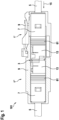
- the connector 1 comprises a plug contact 3 at one end of a cable 5, a contact carrier 7 and a plug housing 9. As explained in more detail below, the connector 1 further comprises a primary locking element 11 (in the Fig. 1 and 2 not shown) and a secondary locking element 13. Furthermore, the connector 1 is sealed by means of seals 61.
- the connector 1 has a data cable 5 with stripped ends and with plug contacts 3 which are accommodated within the contact carrier 7, wherein the contact carrier 7 is arranged in the plug housing 9.
- the contact carrier 7 and the secondary locking element 13 are first provided as separate components ( Fig. 2(a) ).
- the secondary locking element 13 is then reversibly releasably pre-fixed to the contact carrier 7 by pushing it laterally onto the contact carrier in a pre-fixed intermediate position in a radially inward direction 17 ( Fig. 2(b) ).
- the plug contact 3 with the cable 5 connected to it is then inserted into the contact carrier 7 in a longitudinal direction 15 of the cable 5 ( Fig. 2(c) ).
- the secondary locking element 13 can be brought from its intermediate position into a fixed end position by being displaced further towards the contact carrier 7 in the radially inward direction 17 ( Fig. 2(d) ).
- the connector housing 9 is then pushed onto the contact carrier 7 in the longitudinal direction 15 from behind ( Fig. 2(e) ) until both components are correctly positioned relative to each other and lock together ( Fig. 2(f) ).
- the primary locking mechanism is designed, for example, as a locking hook which is arranged elastically spring-loaded on the contact carrier 7 and, in a locking position, engages in a groove of the plug contact 3 accommodated in the contact carrier 7.
- the secondary locking mechanism can be designed to act on the primary locking mechanism in such a way that the secondary locking mechanism prevents the primary locking mechanism from being released.
- the secondary locking mechanism can be designed to directly fix the plug contacts 3 to the contact carrier 7 and thus act in addition to the primary locking mechanism, i.e. as a second primary locking mechanism, so to speak.
- the connector described here is provided with a secondary locking element 13 (in the The SVE 13 of the secondary locking device is designed as a molded part manufactured separately from the contact carrier 7 and the plug housing 9, in particular from a plastic, but a metal blank (possibly overmolded with plastic) or a ceramic molded part is also possible.
- the SVE 13 is moved from a pre-fixed intermediate position, in which the SVE 13 is firmly (clamped) but still detachably arranged on the outside of the contact carrier, by an exclusively radial movement (i.e., for example, by pressing in the direction of the plug contact 3) to a fixed end position in which the SVE 13 is permanently and firmly arranged on the contact carrier 7. Only in the end position does the SVE 13 fix the plug contact 3 to the contact carrier 7. As shown in detail below, a locking section 19 of the SVE 13 reaches through the contact carrier 7 and lies directly on the plug contact 3 under mechanical tension (i.e., for example, it engages in a recess 25, for example in the form of a groove in the plug contact 3). From the intermediate position, the SVE 13 can preferably only be moved into the end position if the recess 25 in the plug contact 3 is located in the plugging direction (radial) of the SEV 13.
- the SVE 13 has an elongated, generally cambered (i.e. curved) shape and is mechanically clamped to the contact carrier 7 in the end position.
- Fig. 3(a) shows a female insert, i.e. a cable end that is designed with a 'female' plug contact 3.
- a primary locking element for example in the form of a primary locking latching hook 49 on the contact carrier 7
- the secondary locking with the SVE 13 described below can engage in a groove-like recess 25 adjacent to a spring basket 63.
- Fig. 3(b) shows a male insert, i.e. a cable end that is designed with a male plug contact 3.
- a primary locking device (such as a locking hook on the contact carrier) can engage in the groove-like recess 25.
- the SVE 13 for the insert male from Fig. 3(b) is in the Fig. 4(a), (b) shown in various perspective views.
- the SVE 13 is designed as a one-piece molded part. It has a generally longitudinally slotted cylindrical shape. In other words, the SVE 13 is designed with a circular outer contour and is provided with an opening 67 in some areas on its side shown in the figure above. The width of the opening 67 corresponds approximately to a width or diameter of the male insert.
- the SVE 13 is particularly mirror-symmetrical to an imaginary central plane.
- the SVE 13 also has various functional sections on a curved, inner side.
- the SVE 13 has a locking section 19, which is designed as a rib 21 protruding transversely to the longitudinal extension.
- An arc-segment-shaped end surface 65 of the locking section 19 is applied to a lateral surface 23 of the insert male plug contact 3 in the region of the recess 25 ( Fig. 3(b) ), i.e. is designed with a contour complementary to this casing surface 23, and in the locked end position rests on the casing surface 23 in the region of the recess 25.
- the secondary locking element 13, the contact carrier 7 and the plug contact 3 are configured and adapted to one another in such a way that the locking section 19, when the secondary locking element 13 has been positioned in the fixed end position, reaches through a region of the contact carrier 7 and rests under mechanical prestress on the casing surface 23 of the plug contact 3 in the region of the groove-shaped recess 25. Accordingly, the plug contact 3 can be secured in the contact carrier 7 by the locking section 19 of the secondary locking element 13 against removal from the contact carrier 7 by pulling in a direction parallel to the longitudinal direction 15 of the cable 5.
- the SVE 13 further comprises two opposing lever sections 27, on which a formation 29 protrudes at a defined angle ⁇ in the direction of a plane of symmetry of the SVE 13.
- the angle ⁇ refers (see Fig. 4(a) ) to a main extension direction of the lever portion 27 in relation to a tangent to an outer circumference of the cylindrical SVE 13.
- the lever portion 27 is formed approximately centrally on an arm 31 which is provided on the SVE 13 and at the free end of which a first latching hook 33 is formed.
- a second locking hook 41 is formed, separated from the arm 31 by a parting line 43, at an axial distance from the lever section 27.
- a third locking hook 45 is formed, again separated axially.
- a support section 69 is also formed substantially centrally to the plane of symmetry.
- a distance between the opposite ends of the lever sections 27 is dimensioned such that these lever sections 27, when the SVE 13 is attached to the contact carrier 7, rest against the outside of the contact carrier 7 under a prestress, i.e. under an elastic deformation of the SVE 13.
- the SVE 13 and the contact carrier 7 are in particular such configured so that the SVE 13 in the intermediate position rests with its lever sections 27 under a mechanical prestress on an outer surface of the contact carrier 7. As a result, the SVE 13 can be pre-fixed to the contact carrier 7 in the intermediate position.
- the SVE 13 and the contact carrier 7 are configured in such a way that when the SVE 13 is moved from the intermediate position to the end position, the two arms 31 are supported by the lever sections 27 projecting therefrom against the associated counter-pressure surfaces 39 (see Fig. 13 ) on the contact carrier 7, are spread apart from each other in such a way that the first locking hooks 33 can engage behind central counter-locking elements 35.
- the locking hooks 33, 41, 45 engage in the associated counter-locking elements 35, 71 (undercuts) (see Fig. 5(b) as in Fig.7 , 8(a) , 8(b) , 9 and 13 shown in an analogous manner for the female insert) on the contact carrier 7.
- the SVE 13 with its arms 31 and the lever sections 27 protruding therefrom as well as the contact carrier 7 are configured such that in particular the first latching hooks 33 are not latched with the associated counter-latching elements 35 in the pre-fixed intermediate position of the SVE 13 and are latched with the associated counter-latching elements 35 in the fixed end position.
- Fig. 5(a) shows the SVE 13 from the Fig. 4(a), (b) in its pre-fixed intermediate position.
- the SVE 13 can be moved into the Fig. 5(b) shown fixed end position.
- the third locking hook 45 engages in an associated undercut on the contact carrier 7 formed by the counter-locking element 71. The same applies to the first and second locking hooks 33, 41.
- Fig. 6a, b show an SVE 13 for a plug contact 3 in the form of a female insert.
- the lever sections 27 in the form of protruding formations 29, a separating gap 43, first locking hooks 33 and second locking hooks 41 and a locking section 19 in the form of a rib 21 are visible.
- one end face is designed as a closed ring.
- Fig. 7(a) shows a perspective view of the contact carrier 7, with which the SVE 13 of the female insert is to interact.
- front-side counter-locking elements 71 can be seen.
- the contact carrier 7 has a tooth-like Projection 79.
- the tooth-like projection 79 protrudes from the contact carrier 7 on its front face in the axial direction and projects in the radial direction at least slightly beyond the inner circumference 77 of the contact carrier 7.
- This tooth-like projection 79 is provided as a stop when inserting the female insert and forms a radially protruding latch that limits the insertion of the female insert.
- Fig. 7(b) illustrates an SVE 13, which is specially designed to work with the Fig. 7(a) contact carrier 7 shown. Since the SVE 13 is to be pushed over the contact carrier 7 in the radially inward direction 17, the tooth-like projection 79 requires an adaptation of the SVE 13 in such a way that a groove-like depression 83 is provided laterally next to the rear front opening 81 or bore, which extends approximately tangentially to the opening 81. The tooth-like projection 79 can be guided in this depression 83 in order to be able to bring the SVE 13 into the pre-fixed intermediate position.
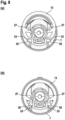
- Fig. 8(a) shows the contact carrier 7 from Fig.7 with the SVE 13 from the Fig. 6(a), (b) in the pre-fixed intermediate position. It can be seen that the two lever sections 27 rest laterally on the outside of the contact carrier 7. The first locking hooks 33 rest on the counter-locking elements 35 and do not yet engage behind the counter-locking elements 35.
- Fig. 8(a) It can also be seen that the SVE 13 is not arranged flush or aligned with the contact carrier 7 in an upper area, but protrudes above an outer boundary of the contact carrier 7, so that in this intermediate position a plug housing 9 cannot yet be pushed over the contact carrier 7.
- the plug housing 9 can only be pushed over the contact carrier 7 (ie perpendicular to the plane of the paper) when the SVE 13 is in the fixed (locked) end position, as shown in Fig. 8(b) is shown.
- the SVE 13 is brought into the end position by a purely inwardly directed radial pushing (ie a pressing in the direction of the contact carrier 7).
- the first locking hooks 33 overlap the associated counter-locking elements 35 on the contact carrier 7, whereby the same also applies to the second and third locking hooks 41, 45 (not shown, as they are outside the plane of the paper).
- the lever sections 27 are slightly tilted and brought into an over-dead center position. In this position the SVE 13 can no longer be detached from the contact carrier 7, in particular the SVE 13 is fixed against the contact carrier 7 due to inherent mechanical stress.
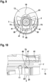
- Fig.9 shows a cross-sectional view through the Fig. 8(a) shown contact carrier 7 with the SVE 13 from Fig. 6(a),(b) .
- the cutting plane is shown in Fig.9 placed so that it intersects the locking section 19 and the second locking hooks 41. It can be seen that the ends of the second locking hooks 41 are received and pre-fixed in a retaining groove 73 on the contact carrier 7.
- the locking section 19 rests almost positively on the outer surface 23 of the insert plug contact 3.
- the ends of the second locking hooks 41 overlap the retaining groove 73 and fix the SVE 13 to the contact carrier 7 with a slight elastic internal stress. To do this, the locking section 19 engages directly on the insert through a recess in the contact carrier 7.
- Fig.9 also shows a primary locking catch hook 49 of a primary locking element 11 in a sectional view.
- the primary locking catch hook 49 is formed outside the image plane on the contact carrier 7 as a freely radially elastically displaceable leg 47 (eg as a tab) and is engaged in the insert of the plug contact 3 in the area of the sectional view. It can be seen that the SVE 13 of the secondary locking is formed radially opposite the primary locking catch hook 49 of the primary locking element 11.
- the leg 47 with the primary locking hook 49 extends essentially in the longitudinal direction 15 of the cable 5 and rests elastically prestressed on the jacket surface 23 in the region of the groove-like recess 25 on the plug contact 3 on a flank of the recess 25 which is located in the cable direction, i.e. in the direction of action of a tensile stress, so that the primary locking imparts an increased pull-off force.
- Fig.10 shows a partially sectioned view of the primary locking catch hook 49 of the primary lock. When a tensile force acts in the cable direction (to the right in the figure), the primary locking catch hook 49 is pressed against a right-hand groove edge 75, which serves as an abutment or stop.
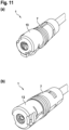
- Fig. 11(a) shows a perspective view of the connector 1 with the plug contact 3 designed as a female insert in the pre-fixed intermediate position.
- Fig. 11(b) shows the connector 1 in the fixed end position. It can be seen that in the intermediate position the SVE 13 still protrudes laterally radially beyond the outer circumference of the contact carrier 7. In the end position the SVE 13 is essentially flush with the contact carrier 7, i.e. the outer circumference of the SVE 13 is essentially flush with the outer circumference of the contact carrier 7. While the SVE 13 in the intermediate position would hinder correct assembly of the connector 1, in particular sliding on the connector housing 9, the connector 1 can be correctly assembled when the SVE 13 has been moved to its end position.
- Fig.1 shows a view of a plug connection system 101, in which the plug connector 1' with the male plug contact 3 and the mating plug connector 1" with the female plug contact 3 are each designed as above, i.e. with an increased pull-off force in the longitudinal direction 15 of the respective cable 5 due to the orientation of the primary locking and further by a SVE 13 each, which comprises a curved molded part, wherein the molded part has at least one tensioning element on the inside facing the cable 5, which is designed as opposing lever sections 27, and at least one second or third locking element or locking hook 41, 45 (preferably axially spaced from the lever sections 27).
- a first locking element or locking hook 33 is also provided in the circumferential direction of the lever section 27.
- the connector system 101 is in Fig.1 in a configuration in which the SVE 13 on the connector 1' was correctly moved into its final position during assembly. It can be seen that this SVE 13 does not protrude laterally beyond the circumference of the associated contact carrier 7, which would otherwise prevent the two connector housings 9 of the respective connectors 1', 1" from being pushed together and locked together in the intended manner. In such a case of incorrect assembly, this could be recognized when assembling the plug connection system 101, so that the incorrect assembly of the SVE 13 on the connector 1' would then be noticed at the latest.
- the plug connection system 101 is designed to be sealed.
- Seals 61 such as lamellae of a lamella seal, are arranged on the contact carrier 7 on the side facing the respective cable 5. These seals 61 reduce the ingress of moisture between the cable sheath and the inside of the contact carrier 7. Furthermore, a seal 61 is arranged between the outside of the contact carrier 7 and the respective plug housing 9. Finally, a seal 61 is formed on the outside of the contact carrier 7, which cooperates in a sealing manner with the inside of the plug housing 9 of the other cable 5.
- Fig. 13 shows a cross section through the Fig. 12 shown plug connection system 101. The cutting plane is laid through the lever section 27.
- Fig. 14 shows an alternative way of attaching the SVE 13 to the contact carrier 7.
- a radially protruding knob 51 is provided, which engages in a constricted recess 53 in the form of a groove or cutout in the SVE 13.
- the knob 51 In the pre-locked intermediate position of the SVE 13, the knob 51 is located in a wide first area 55 of the recess 53. In the locked end position, the knob 51 is located in a wide second area 57 of the recess 53. Both wide areas 55, 57 are separated from one another by a narrowed transition area 59, so that in order to move the SVE 13 from the pre-locked intermediate position to the locked end position, the narrowed transition area 59 must be passed through the knob 51.
- the nub 51 is slightly wider than the transition area 59 and the nub and/or the constricted recess 53 are elastically deformable at least in the area of the transition area 59.
- the groove-nub combination can be provided in addition to or as an alternative to the previously described pre-fixing by means of the pre-tensioned contact of the protruding formations 29 of the lever sections 27, in particular when the diameter of the cable 5 (and thus of the SVE 13) is so large that fixing the SVE 13 by the locking hooks and locking elements would not generate sufficient holding force.
Landscapes
- Details Of Connecting Devices For Male And Female Coupling (AREA)
Applications Claiming Priority (1)
| Application Number | Priority Date | Filing Date | Title |
|---|---|---|---|
| DE102023101706.3A DE102023101706A1 (de) | 2023-01-24 | 2023-01-24 | Elektrischer steckverbinder mit radial zu betätigender sekundärverriegelung, und elektrisches steckverbindungssystem |
Publications (1)
| Publication Number | Publication Date |
|---|---|
| EP4407810A1 true EP4407810A1 (fr) | 2024-07-31 |
Family
ID=89224369
Family Applications (1)
| Application Number | Title | Priority Date | Filing Date |
|---|---|---|---|
| EP23217978.8A Pending EP4407810A1 (fr) | 2023-01-24 | 2023-12-19 | Connecteur électrique à verrouillage secondaire à actionnement radial, et système de connexion électrique |
Country Status (5)
| Country | Link |
|---|---|
| US (1) | US20240250465A1 (fr) |
| EP (1) | EP4407810A1 (fr) |
| KR (1) | KR102948540B1 (fr) |
| CN (1) | CN117855954A (fr) |
| DE (1) | DE102023101706A1 (fr) |
Families Citing this family (1)
| Publication number | Priority date | Publication date | Assignee | Title |
|---|---|---|---|---|
| US12230947B2 (en) * | 2022-08-09 | 2025-02-18 | Lear Corporation | Cable fastening system for electrical connector assembly |
Citations (5)
| Publication number | Priority date | Publication date | Assignee | Title |
|---|---|---|---|---|
| US5851128A (en) * | 1995-01-19 | 1998-12-22 | Sumitomo Wiring Systems, Ltd. | Electrical connector |
| DE102018113365A1 (de) * | 2018-06-05 | 2019-12-05 | Rosenberger Hochfrequenztechnik Gmbh & Co. Kg | Modulares Steckverbindersystem |
| EP3713018A1 (fr) | 2019-03-20 | 2020-09-23 | Rosenberger Hochfrequenztechnik GmbH & Co. KG | Connecteur enfichable électrique, fixation secondaire et procédé de montage d'un connecteur enfichable électrique |
| US10797427B2 (en) * | 2018-11-12 | 2020-10-06 | Raydiall | Connector housing equipped with an improved cable terminal position assurance (TPA) device |
| US20220384983A1 (en) * | 2021-06-01 | 2022-12-01 | Hosiden Corporation | Multiple coaxial connector |
Family Cites Families (4)
| Publication number | Priority date | Publication date | Assignee | Title |
|---|---|---|---|---|
| GB9216994D0 (en) * | 1992-08-11 | 1992-09-23 | Amp Gmbh | Electrical connector having secondary locking mechanism |
| US7234877B2 (en) * | 2004-10-27 | 2007-06-26 | Panduit Corp. | Fiber optic industrial connector |
| EP2705395B1 (fr) * | 2011-05-04 | 2020-01-08 | The Siemon Company | Connecteur de fibre optique à changement de polarité |
| US11183793B2 (en) * | 2018-10-08 | 2021-11-23 | Aptiv Technologies Limited | Connector system with a terminal retaining device having a reverse hinged lock feature |
-
2023
- 2023-01-24 DE DE102023101706.3A patent/DE102023101706A1/de active Pending
- 2023-12-19 EP EP23217978.8A patent/EP4407810A1/fr active Pending
-
2024
- 2024-01-05 US US18/405,317 patent/US20240250465A1/en active Pending
- 2024-01-18 CN CN202410074938.1A patent/CN117855954A/zh active Pending
- 2024-01-19 KR KR1020240008963A patent/KR102948540B1/ko active Active
Patent Citations (5)
| Publication number | Priority date | Publication date | Assignee | Title |
|---|---|---|---|---|
| US5851128A (en) * | 1995-01-19 | 1998-12-22 | Sumitomo Wiring Systems, Ltd. | Electrical connector |
| DE102018113365A1 (de) * | 2018-06-05 | 2019-12-05 | Rosenberger Hochfrequenztechnik Gmbh & Co. Kg | Modulares Steckverbindersystem |
| US10797427B2 (en) * | 2018-11-12 | 2020-10-06 | Raydiall | Connector housing equipped with an improved cable terminal position assurance (TPA) device |
| EP3713018A1 (fr) | 2019-03-20 | 2020-09-23 | Rosenberger Hochfrequenztechnik GmbH & Co. KG | Connecteur enfichable électrique, fixation secondaire et procédé de montage d'un connecteur enfichable électrique |
| US20220384983A1 (en) * | 2021-06-01 | 2022-12-01 | Hosiden Corporation | Multiple coaxial connector |
Also Published As
| Publication number | Publication date |
|---|---|
| KR20240117052A (ko) | 2024-07-31 |
| CN117855954A (zh) | 2024-04-09 |
| DE102023101706A1 (de) | 2024-07-25 |
| KR102948540B1 (ko) | 2026-04-06 |
| US20240250465A1 (en) | 2024-07-25 |
Similar Documents
| Publication | Publication Date | Title |
|---|---|---|
| EP3937313B1 (fr) | Connecteur à fiches électrique | |
| EP4127543B1 (fr) | Raccord de type enfichable ayant un verrouillage de préassemblage | |
| EP1745528B1 (fr) | Connexion a fiche etancheifiee a travers une paroi de separation et procede de montage | |
| DE102012209298B4 (de) | Elektrischer Steckverbinder, Steckverbinderanordnung sowie Verfahren zum Montieren des Steckverbinders | |
| WO2004109865A1 (fr) | Raccord electrique a parties enfichables | |
| DE19500959A1 (de) | Elektrischer Steckverbinder | |
| EP4066325B1 (fr) | Appareil de verrouillage secondaire | |
| WO2015150048A1 (fr) | Assurance de position de connecteur (cpa) et ensemble connecteur comprenant une assurance de position de connecteur | |
| EP3176885B1 (fr) | Systeme de connecteur a fiches | |
| EP3679631B1 (fr) | Connecteur enfichable comprenant des crochets de verrouillage servant à fixer son support de contact dans son boîtier extérieur | |
| EP3895256B1 (fr) | Connecteur enfichable rond présentant un dispositif de verrouillage | |
| EP3259810B1 (fr) | Connecteur avec un élément amortisseur | |
| DE102017003296B3 (de) | Steckverbinder und Verfahren zur Herstellung einer Steckverbindung | |
| EP4000139B1 (fr) | Élément de contact | |
| DE102012104857B4 (de) | Elektrische Steckverbindung | |
| EP3847724A1 (fr) | Connecteur électrique enfichable et connexion enfichable, système haute tension et procédé de verrouillage d'une connexion électrique enfichable | |
| DE102021129676A1 (de) | Steckverbindung mit Verriegelungs- und Entriegelungsvorrichtung | |
| EP4407810A1 (fr) | Connecteur électrique à verrouillage secondaire à actionnement radial, et système de connexion électrique | |
| EP1936755B1 (fr) | Connecteur comportant une prise et une douille avec un support de contacts et une collerette de protection | |
| EP3288121A1 (fr) | Connecteur enfichable entièrement hermétique doté des forces de rétention améliorées | |
| DE202008005493U1 (de) | Steckverbindung für die Außenanwendung, insbesondere für Solarpanels | |
| WO2012025421A1 (fr) | Connecteur, en particulier connecteur photovoltaïque | |
| DE202012101656U1 (de) | Kabelverbindungsvorrichtung für ein Kabel | |
| DE102009039354B4 (de) | Elektrischer Steckverbinder | |
| DE10326834B4 (de) | Steckverbinder |
Legal Events
| Date | Code | Title | Description |
|---|---|---|---|
| PUAI | Public reference made under article 153(3) epc to a published international application that has entered the european phase |
Free format text: ORIGINAL CODE: 0009012 |
|
| STAA | Information on the status of an ep patent application or granted ep patent |
Free format text: STATUS: THE APPLICATION HAS BEEN PUBLISHED |
|
| AK | Designated contracting states |
Kind code of ref document: A1 Designated state(s): AL AT BE BG CH CY CZ DE DK EE ES FI FR GB GR HR HU IE IS IT LI LT LU LV MC ME MK MT NL NO PL PT RO RS SE SI SK SM TR |
|
| STAA | Information on the status of an ep patent application or granted ep patent |
Free format text: STATUS: REQUEST FOR EXAMINATION WAS MADE |
|
| 17P | Request for examination filed |
Effective date: 20240812 |
|
| RBV | Designated contracting states (corrected) |
Designated state(s): AL AT BE BG CH CY CZ DE DK EE ES FI FR GB GR HR HU IE IS IT LI LT LU LV MC ME MK MT NL NO PL PT RO RS SE SI SK SM TR |
|
| STAA | Information on the status of an ep patent application or granted ep patent |
Free format text: STATUS: EXAMINATION IS IN PROGRESS |
|
| 17Q | First examination report despatched |
Effective date: 20251125 |