EP4410079A2 - Système de prose de force et véhicule agricole - Google Patents
Système de prose de force et véhicule agricole Download PDFInfo
- Publication number
- EP4410079A2 EP4410079A2 EP24160737.3A EP24160737A EP4410079A2 EP 4410079 A2 EP4410079 A2 EP 4410079A2 EP 24160737 A EP24160737 A EP 24160737A EP 4410079 A2 EP4410079 A2 EP 4410079A2
- Authority
- EP
- European Patent Office
- Prior art keywords
- piston
- output shaft
- power take
- stub
- pto
- Prior art date
- Legal status (The legal status is an assumption and is not a legal conclusion. Google has not performed a legal analysis and makes no representation as to the accuracy of the status listed.)
- Withdrawn
Links
Images

Classifications
-
- F—MECHANICAL ENGINEERING; LIGHTING; HEATING; WEAPONS; BLASTING
- F16—ENGINEERING ELEMENTS AND UNITS; GENERAL MEASURES FOR PRODUCING AND MAINTAINING EFFECTIVE FUNCTIONING OF MACHINES OR INSTALLATIONS; THERMAL INSULATION IN GENERAL
- F16D—COUPLINGS FOR TRANSMITTING ROTATION; CLUTCHES; BRAKES
- F16D25/00—Fluid-actuated clutches
- F16D25/06—Fluid-actuated clutches in which the fluid actuates a piston incorporated in, i.e. rotating with the clutch
- F16D25/061—Fluid-actuated clutches in which the fluid actuates a piston incorporated in, i.e. rotating with the clutch the clutch having interengaging clutch members
-
- A—HUMAN NECESSITIES
- A01—AGRICULTURE; FORESTRY; ANIMAL HUSBANDRY; HUNTING; TRAPPING; FISHING
- A01B—SOIL WORKING IN AGRICULTURE OR FORESTRY; PARTS, DETAILS, OR ACCESSORIES OF AGRICULTURAL MACHINES OR IMPLEMENTS, IN GENERAL
- A01B71/00—Construction or arrangement of setting or adjusting mechanisms, of implement or tool drive or of power take-off; Means for protecting parts against dust, or the like; Adapting machine elements to or for agricultural purposes
- A01B71/06—Special adaptations of coupling means between power take-off and transmission shaft to the implement or machine
-
- F—MECHANICAL ENGINEERING; LIGHTING; HEATING; WEAPONS; BLASTING
- F16—ENGINEERING ELEMENTS AND UNITS; GENERAL MEASURES FOR PRODUCING AND MAINTAINING EFFECTIVE FUNCTIONING OF MACHINES OR INSTALLATIONS; THERMAL INSULATION IN GENERAL
- F16D—COUPLINGS FOR TRANSMITTING ROTATION; CLUTCHES; BRAKES
- F16D21/00—Systems comprising a plurality of actuated clutches
- F16D21/02—Systems comprising a plurality of actuated clutches for interconnecting three or more shafts or other transmission members in different ways
- F16D21/04—Systems comprising a plurality of actuated clutches for interconnecting three or more shafts or other transmission members in different ways with a shaft carrying a number of rotatable transmission members, e.g. gears, each of which can be connected to the shaft by a clutching member or members between the shaft and the hub of the transmission member
-
- F—MECHANICAL ENGINEERING; LIGHTING; HEATING; WEAPONS; BLASTING
- F16—ENGINEERING ELEMENTS AND UNITS; GENERAL MEASURES FOR PRODUCING AND MAINTAINING EFFECTIVE FUNCTIONING OF MACHINES OR INSTALLATIONS; THERMAL INSULATION IN GENERAL
- F16H—GEARING
- F16H63/00—Control outputs from the control unit to change-speed- or reversing-gearings for conveying rotary motion or to other devices than the final output mechanism
- F16H63/02—Final output mechanisms therefor; Actuating means for the final output mechanisms
- F16H63/30—Constructional features of the final output mechanisms
- F16H63/3023—Constructional features of the final output mechanisms the final output mechanisms comprising elements moved by fluid pressure
-
- B—PERFORMING OPERATIONS; TRANSPORTING
- B60—VEHICLES IN GENERAL
- B60K—ARRANGEMENT OR MOUNTING OF PROPULSION UNITS OR OF TRANSMISSIONS IN VEHICLES; ARRANGEMENT OR MOUNTING OF PLURAL DIVERSE PRIME-MOVERS IN VEHICLES; AUXILIARY DRIVES FOR VEHICLES; INSTRUMENTATION OR DASHBOARDS FOR VEHICLES; ARRANGEMENTS IN CONNECTION WITH COOLING, AIR INTAKE, GAS EXHAUST OR FUEL SUPPLY OF PROPULSION UNITS IN VEHICLES
- B60K17/00—Arrangement or mounting of transmissions in vehicles
- B60K17/28—Arrangement or mounting of transmissions in vehicles characterised by arrangement, location, or type of power take-off
-
- B—PERFORMING OPERATIONS; TRANSPORTING
- B60—VEHICLES IN GENERAL
- B60Y—INDEXING SCHEME RELATING TO ASPECTS CROSS-CUTTING VEHICLE TECHNOLOGY
- B60Y2200/00—Type of vehicle
- B60Y2200/20—Off-Road Vehicles
- B60Y2200/22—Agricultural vehicles
- B60Y2200/221—Tractors
-
- F—MECHANICAL ENGINEERING; LIGHTING; HEATING; WEAPONS; BLASTING
- F16—ENGINEERING ELEMENTS AND UNITS; GENERAL MEASURES FOR PRODUCING AND MAINTAINING EFFECTIVE FUNCTIONING OF MACHINES OR INSTALLATIONS; THERMAL INSULATION IN GENERAL
- F16D—COUPLINGS FOR TRANSMITTING ROTATION; CLUTCHES; BRAKES
- F16D11/00—Clutches in which the members have interengaging parts
- F16D2011/004—Clutches in which the members have interengaging parts using an internal or intermediate axially slidable sleeve, coupling both components together, whereby the intermediate sleeve is arranged internally at least with respect to one of the components
-
- F—MECHANICAL ENGINEERING; LIGHTING; HEATING; WEAPONS; BLASTING
- F16—ENGINEERING ELEMENTS AND UNITS; GENERAL MEASURES FOR PRODUCING AND MAINTAINING EFFECTIVE FUNCTIONING OF MACHINES OR INSTALLATIONS; THERMAL INSULATION IN GENERAL
- F16H—GEARING
- F16H2200/00—Transmissions for multiple ratios
- F16H2200/0004—Transmissions for multiple ratios comprising a power take off shaft
-
- F—MECHANICAL ENGINEERING; LIGHTING; HEATING; WEAPONS; BLASTING
- F16—ENGINEERING ELEMENTS AND UNITS; GENERAL MEASURES FOR PRODUCING AND MAINTAINING EFFECTIVE FUNCTIONING OF MACHINES OR INSTALLATIONS; THERMAL INSULATION IN GENERAL
- F16H—GEARING
- F16H2200/00—Transmissions for multiple ratios
- F16H2200/003—Transmissions for multiple ratios characterised by the number of forward speeds
- F16H2200/0034—Transmissions for multiple ratios characterised by the number of forward speeds the gear ratios comprising two forward speeds
Definitions
- the invention relates to a power take-off system according to the preamble of independent claim 1 and an agricultural vehicle according to the preamble of independent claim 8.
- power take-off systems are provided at the front and/or rear of agricultural vehicles, in particular towing vehicles, tractors or tugs.
- the power take-off systems comprise a drivable output shaft and a power take-off shaft stub to which an implement drive shaft can be attached and from which an implement or attachment can derive torque.
- Typical implements that require a drive are balers, power harrows and sprayers.
- the known PTO systems can provide different speeds and/or enable switching of the operating modes of the PTO systems in a load-free state.
- Modern PTO systems can have between 1 and 4 gears.
- PTO stumps with gearing with 6, 21, 20 or 22 teeth are used in accordance with ISO 500, in which the PTO stumps are categorised according to type 1-4.
- ISO 500 in which the PTO stumps are categorised according to type 1-4.
- a different geometry must be provided.
- agricultural vehicles can be equipped with PTO systems that have two gears. A first gear with an output speed of 540 rpm and a second gear with an output speed of 1000 rpm at the nominal engine speed of the tractor.
- a PTO stub that operates at 540 rpm can have a gearing with 6 teeth, and a PTO stub that operates at 1000 rpm can have a gearing with 20 or 21 teeth.
- the different design of the PTO stub for the different operating speeds can serve to prevent an implement designed for 540 rpm from being accidentally attached to a vehicle designed for 1000 rpm.
- the PTO system may be operable by means of an electrical switch and/or software.
- additional sensors are provided on the PTO system to detect which end of the PTO stub or which PTO stub is located on the PTO system.
- Another possibility is to mechanically block the first or second gear if the operator tries to activate the wrong output speed for the attached implement.
- the EP 2 922 721 A1 reveals such a PTO system.
- PTO systems and vehicles require too much installation space and are expensive.
- PTO systems are structurally complicated, as they require sensors to detect the PTO stub. This makes the PTO systems prone to repairs and high levels of wear.
- a power take-off system for an agricultural vehicle comprises an output shaft with a socket for a power take-off shaft stub provided at one end of the output shaft, wherein the PTO shaft stub can be arranged at least partially, in particular also completely, in the socket.
- the PTO shaft system can therefore comprise the PTO shaft stub.
- the output shaft has a control valve that is arranged, in particular integrated, in the output shaft.
- the output shaft, in particular the control valve comprises a valve bore that extends axially from the socket, in particular from a base of the socket, into the output shaft.
- the output shaft in particular the control valve, further comprises a first piston that is arranged within the valve bore in the output shaft so that it can be adjusted, preferably moved and/or displaced and/or adjusted.
- the PTO shaft system in particular the output shaft, further comprises a switching element that is adjustable by means of the first piston, in particular also adjustable and/or movable and/or displaced.
- the PTO shaft system also comprises a first gear and a second gear that can be brought into engagement with the output shaft by means of the switching element, preferably can be brought into engagement in a rotationally fixed manner.
- the first piston is adjustable, in particular in an axial direction of the output shaft, between a first position in which the first piston adjusts the switching element such that the first gear is in engagement with the switching element, and a second position in which the first piston adjusts the switching element such that the second gear is in engagement with the switching element.
- the output shaft in particular the control valve, has a second piston which is arranged at least partially on, in particular in the first piston, preferably movable and/or displaceable and/or adjustable, particularly preferably arranged axially movable and/or displaceable, for example within a piston bore in the first piston.
- the second piston can also be arranged within the valve bore in the output shaft so as to be adjustable, preferably movable and/or displaceable and/or adjustable, particularly preferably axially movable and/or displaceable.
- the first piston and thus in particular also the switching element, can be adjusted into the neutral position by means of the second piston, in particular can be moved and/or displaced and/or adjusted.
- the PTO system can be a multi-stage PTO system.
- the PTO system can be arranged on the agricultural vehicle, in particular at the front, rear and/or in the middle.
- the PTO system can comprise a PTO control and/or an input shaft.
- the PTO system can comprise a first and a second gear pair.
- the first gear pair can comprise the first gear and a third gear.
- the second gear pair can comprise the second gear and a fourth gear.
- the third and/or fourth gear can be connected to the input shaft in a rotationally fixed manner.
- the PTO system can also comprise three or four or more gear pairs, with at least one gear per gear pair being switchable.
- Each gear pair can comprise at least one gear that is connected to the input shaft and another gear that can be connected to the output shaft in a rotationally fixed manner by means of the switching element.
- the input shaft can be arranged with the output shaft between an engine output and the PTO shaft stub.
- the input shaft can be drivably connected to the output shaft by means of a gear pair.
- the input shaft can be drivably coupled or coupleable to the output shaft by means of the first or second gear pair.
- the switching element can be arranged on the outer surface of the output shaft.
- the switching element can be in engagement with the output shaft, preferably in a rotationally fixed manner.
- the switching element can be connected or coupled to the first piston, in particular formed as part of the first piston or attached to the first piston.
- the switching element makes it possible to connect a gear, in particular the first or second gear, in a rotationally fixed manner to the Output shaft, i.e. to operate the PTO system with at least two gears.
- the first position can correspond to the first gear and the second position to the second gear. With an arrangement that operates two gears with one switching element, a compact design can be achieved.
- Two or more switching elements can also be provided, in particular the output shaft can have a first and a second switching element with which the first and second gears can be switched individually.
- the input shaft can also have a third switching element.
- the switching element In the neutral position, the switching element cannot engage with any gear, in particular neither with the first or second gear.
- the switching element can thus be designed and/or arranged in such a way that it enables the gears, in particular the first or second gear, to be connected to the output shaft in a rotationally fixed manner or to operate them in freewheel mode in the neutral position.
- the first piston can therefore be displaceable in the axial direction of the output shaft between the first position and/or second position and/or the neutral position, so that the switching element can also be adjusted in the axial direction of the output shaft.
- the PTO system can be operated in first gear at the lower speed, in particular 540 rpm. If the piston is in the second position, in which the first piston adjusts the switching element such that the second gear is in engagement with the switching element, the PTO system can be operated in second gear at the higher speed, in particular 1000 rpm.
- the first piston can also be adjustable between a third, fourth or more positions. In the third position, the first piston can adjust the switching element such that a third gear is in engagement with the switching element. In the fourth position, the first piston can adjust the switching element such that a fourth gear is in engagement with the switching element.
- the two-part design of the piston is essential for the invention, which allows a reduction in the installation space for the output shaft, as additional coupling and switching elements for coupling the gears and switching to the neutral position are not required.
- the PTO system is structurally simpler, so that, for example, the susceptibility to repairs and/or wear of the PTO system can be reduced.
- the second piston in particular within the piston bore, is adjustable, preferably adjustable and/or displaceable by means of the PTO shaft stub, in particular also depending on an orientation of the PTO shaft stub in the socket, in such a way that a movement of the first piston into the second position is blocked by means of the second piston, thus in particular also an adjustment of the switching element is at least partially prevented.
- the first piston can be blocked in the socket by means of the second piston depending on an orientation and/or arrangement of the PTO shaft stub, in particular a first or second stub end.
- the second piston can therefore be adjustable, in particular displaceable and/or movable by means of the PTO shaft stub between a first position in which the second piston at least partially protrudes into the socket and the second piston can be at least partially received in a recess in the PTO shaft stub, and a second position in which the PTO shaft stub adjusts the second piston in such a way that it blocks the first piston, so that a movement of the first piston into the second position is prevented.
- the PTO shaft stub can have a first stub end with a first profile, in particular a recess, and a first toothing and/or a second stub end with a second profile and a second toothing.
- the PTO shaft stub can therefore be a short shaft with one or two or more toothings, one for the drive and one for the output.
- a third toothing can be used for adaptation to different universal joint toothings. be provided.
- two or more PTO stub shafts can also be exchanged.
- the PTO stub with the first stub end can be arranged in the socket, wherein the recess at the first stub end can accommodate the second piston, which at least partially protrudes into the socket.
- the first piston can be adjustable to the first and second positions.
- the PTO stub can also be arranged with the second stub end in the socket, wherein the second piston protruding into the socket is adjusted from the second stub end in the direction of the first piston.
- the first piston can only be adjusted to the first position and adjustment of the first piston to the second position can be blocked or is blocked by means of the second piston.
- two PTO stub shafts each with a profile and a toothing at the first stub end, can also be provided.
- the socket can also comprise a releasable locking mechanism for securing the PTO stub shaft.
- a mechanism can be provided for blocking the second position of the first piston, i.e. the gear with the higher speed.
- this can automatically prevent the engagement of the higher speed PTO stub depending on an orientation of the PTO stub in the socket or the PTO stub type.
- the reliability of the PTO system is improved and the use of sensors is avoided. This represents a significant improvement in the safety of the PTO system and requires that the PTO stub is arranged in the correct orientation or the correct PTO stub type is arranged in the socket before a corresponding speed can be activated.
- the second piston comprises a first piston element and a second piston element and a third piston element, wherein the first piston element is at least partially adjustably arranged in the first piston, the second piston element is at least partially adjustably arranged in the first piston element and the third piston element is at least partially adjustably arranged in the second piston element.
- the first, second and third piston elements can be adjustably arranged, preferably movable and/or be arranged so as to be displaceable and/or adjustable, particularly preferably arranged so as to be axially movable and/or displaceable.
- the first piston element can, for example, be arranged so as to be adjustably within the piston bore in the first piston.
- first piston element can also be arranged so as to be adjustably within the valve bore in the output shaft, preferably arranged so as to be movable and/or displaceable and/or adjustably, particularly preferably arranged so as to be axially movable and/or displaceable.
- the second piston element can, for example, be arranged so as to be adjustably within a further piston bore in the first piston element.
- the second piston element can also be arranged so as to be adjustably within the valve bore in the output shaft, preferably arranged so as to be movable and/or displaceable and/or adjustably, particularly preferably arranged so as to be axially movable and/or displaceable.
- the third piston element can be arranged so as to be adjustably at least partially within a third piston bore in the second piston element.
- the third piston element can at least partially protrude into the socket and/or the further piston bore and/or can also be arranged so as to be adjustable within the valve bore in the output shaft, preferably movable and/or displaceable and/or adjustable, particularly preferably axially movable and/or displaceable.
- the third piston element can be connected to the first piston, in particular coupled to the first piston or fastened to it.
- the third piston element can be adjustable, preferably adjustable and/or displaceable, by means of the PTO stub, depending on an orientation of the PTO stub in the socket, in such a way that a movement of the first piston into the second position is blocked by means of the first and second and third piston elements, thus in particular also preventing an adjustment of the switching element.
- This measure enables greater damping of the mechanism, so that the susceptibility to repairs and/or wear is reduced.
- the second piston element is mounted in the first piston element by means of a first return element, in particular mounted in an equilibrium position
- the third piston element comprises a first and second piston pieces which are adjustably arranged in the second piston element, wherein a second return element is arranged between the first and second piston pieces, in particular the first and second piston pieces are mounted in an equilibrium position by means of the second return element.
- the first and/or second return element can be an elastic element, in particular a spring element or a spring.
- the first and/or second return element can be in an equilibrium or rest position in the neutral position.
- the first return element can preload the first and/or second piston element, in particular the first piston element, in such a way that the first piston can be adjusted, in particular displaced and/or moved, back into the neutral position by means of the first return element.
- the first piston can in particular be adjusted from the first and second position back into the neutral position by means of the first return element.
- the second return element can preload the third piston element in such a way that the first piston can be adjusted, in particular displaced and/or moved, back into the neutral position by means of the second return element.
- the third piston element can be preloaded in the second piston element by means of the second return element.
- the first and second piston pieces can be connected to one another by means of the second return element and/or coupled by means of the second return element, in particular the second return element can be at least partially fastened to the first and second piston pieces.
- the second return element and the first and second piston pieces can be arranged along an axis of the output shaft, in particular arranged coaxially along the axis of the output shaft.
- the first piston piece can be connected to the first piston, in particular coupled to the first piston or fastened to it.
- the second piston piece can protrude into the socket.
- the first piston piece can be adjustable, preferably adjustable and/or displaceable, by means of the power take-off shaft stub, depending on an orientation of the power take-off shaft stub in the socket, such that the second return element preloads the first and second piston pieces and enables a movement of the first piston into the second position by means of the first and second piston elements and of the first and second piston pieces is blocked, thus in particular an adjustment of the switching element is prevented.
- the first and second return elements enable greater damping of the PTO system and automatic mechanical operability.
- a first fluid delivery bore is provided in the output shaft, in particular at least partially in the output shaft and at least partially in the first piston, through which a pressurized fluid, in particular hydraulic fluid, can be delivered into the output shaft, in particular the valve bore, in such a way that the first piston is moved into the first position
- a second fluid delivery bore is provided in the output shaft, through which the pressurized fluid can be delivered into the output shaft, in particular the valve bore, in such a way that the first piston is moved into the second position.
- the control valve can comprise the first and second fluid delivery bores.
- the first fluid delivery bore can be in two parts. The first fluid delivery bore can therefore be formed at least partially in the output shaft and at least partially in the first piston.
- the part of the first fluid delivery bore that is formed in the piston can be arranged at least partially in the part of the first fluid delivery bore that is formed in the output shaft.
- the part of the first fluid conveying bore that is arranged in the output shaft can therefore have a different diameter, in particular a larger diameter, than the part of the first fluid conveying bore that is arranged in the first piston.
- the pressurized fluid can be guided in the first fluid conveying bore via the output shaft into the first piston into the piston bore, so that the first piston is moved into the first position.
- the piston bore can be designed at least partially, but also completely, as a first chamber and can fill with the pressurized fluid, so that the first piston is moved into the first position.
- the pressurized fluid can be guided in the second fluid conveying bore via the output shaft between the first piston and the base of the valve bore, so that the first piston is moved into the second position.
- the volume between the first piston and the base of the valve bore can be be at least partially, but also completely, designed as a second chamber and fill with the pressurized fluid so that the first piston is moved to the second position.
- the power take-off system or the agricultural vehicle can also comprise means, for example hoses and/or pipes and/or lines and/or a pump, for supplying the fluid to the respective delivery bore.
- the first or second position can therefore be activated by the pressurized fluid which can be delivered through the first and/or second fluid delivery bore in the output shaft.
- this enables a structurally simpler design of the power take-off system, since mechanical connections in the form of shift rods, shift forks and shift linkages in the transmission are eliminated.
- the mechanism for selecting the first and second gear can be controlled in a simple manner, in particular hydraulically. Due to the structurally optimized design, the power take-off system is more durable and easier to operate.
- the PTO shaft stub has a first and a second stub end.
- the first and second stub ends can be arranged at least partially, in particular completely, in the socket and the first stub end has a different toothing than the second stub end.
- the first stub end can have a first toothing with 6, 21, 22 or 22 teeth or a cylindrical shape without teeth.
- the second stub end can have a second toothing with 6, 21, 22 or 22 teeth or a cylindrical shape without teeth.
- the toothing with 6 teeth can have a spline profile with a diameter of 35 mm.
- the toothing with 20 or 21 teeth can have a spline profile with a diameter of 35 mm and the toothing with 21 teeth can have a spline profile with a diameter of 45 mm. Furthermore, a toothing with 22 teeth can be used which has a spline profile with a diameter of 57.5 mm.
- this makes it possible to determine which stump end is arranged in the socket depending on the arrangement of the respective teeth in the socket.
- the first stump end in particular a base of the first stump end, has a first profile with a recess and the second stump end, in particular a base of the second stump end, has a second profile that is flat, i.e. has no recess.
- the first profile of the first stump end can therefore, due to the recess, at least partially, in particular completely, accommodate the protruding second piston piece when the latter is arranged in the recess. As a result, the first piston is not blocked, and can therefore be adjusted to the first and second positions.
- the second stump end with the second profile can adjust the second piston piece in such a way, in particular move it in the direction of the first piston piece, that a movement of the first piston can be blocked by means of the first piston piece, in particular that an adjustment of the switching element to the second position is prevented.
- the first stub end which has a recess and the first toothing, in particular with 6 teeth, is arranged in the socket, the first piston can be adjustable into the first and second positions, so that activation of the lower speed (540 or 1000 revolutions per minute) and the higher speed (1000 or 1300 revolutions per minute) is possible.
- the first piston can only be adjustable into the first position, so that only activation of the lower speed and not activation of the higher speed is possible. This advantageously makes it possible to create a PTO system that is less susceptible to repairs and wear.
- the invention further relates to an agricultural vehicle with a power take-off system according to one of claims 1 to 7.
- the agricultural vehicle can be a towing vehicle, tractor or tug.
- the power take-off system can be arranged at the front and/or in the middle and/or at the rear of the vehicle in the direction of travel of the vehicle.
- the agricultural vehicle can comprise a power take-off system in order to a cardan shaft to provide power for a working device.
- the agricultural vehicle according to the invention has the advantages of the power take-off shaft system according to the invention described above.
- the power take-off system according to the invention and/or the agricultural vehicle can have a control device, in particular two or more control devices, which can be operated to control and/or regulate, preferably adjust, particularly preferably set and/or change the power take-off system and/or the agricultural vehicle, in particular the control valve, in such a way that the first piston can be adjusted between the first and second position and the neutral position.
- the power take-off system and/or the agricultural vehicle can be controlled and/or regulated using the control unit.
- the control unit can be provided on the power take-off system and/or the agricultural vehicle.
- the control unit can also be distributed between the power take-off system and the agricultural vehicle.
- the control unit and the power take-off system and/or the agricultural vehicle, in particular a first and/or second valve for controlling or regulating the supply of fluid into the first and second fluid delivery bores, can be connected to one another by means of a cable or wire or wirelessly, for example by radio.
- FIG. 1 shows a schematic side view of a first embodiment of the agricultural vehicle 10 according to the invention, which can move in the forward direction 18.
- the vehicle 10 shown schematically comprises a power take-off shaft system 12 according to the invention.
- the power take-off shaft system 12 can be used to enable a working device to be supplied with drive power.
- the power take-off shaft system 12 is usually provided in the forward direction of travel at the front, in the middle and/or at the rear of the vehicle 10, in Figure 1 rear.
- a working device can be coupled and connected to the vehicle 10 and the power take-off system 12.
- Typical speeds of the power take-off system 12 can be 540 and/or 1000 and/or 1300 revolutions per minute. It can also be possible to operate the power take-off system 12 at the speeds mentioned in a reduced power mode.
- the agricultural vehicle 10 can have a control device 16 and/or a display device 14.
- the control device 16 can also be designed as part of the power take-off system 12.
- FIG 2 shows a schematic representation of a power take-off shaft system 12 according to the invention, in particular parts of the power take-off shaft system 12, with a first piston 110 in a neutral position.
- the power take-off shaft system 12 shown essentially corresponds to the one in Figure 1 shown PTO system 12, so that only the differences will be discussed below.
- the PTO system 12 comprises an output shaft 100 with a socket 102 provided at one end of the output shaft for a PTO stub 104, wherein the PTO stub 104 can be arranged at least partially in the socket 102.
- the output shaft 100 also has a control valve 106 which is arranged in the output shaft 100.
- the output shaft 100 in particular the control valve 106, comprises a valve bore 108 which extends axially from the socket 106 into the output shaft 100 and comprises a first piston 110 which is adjustably arranged within the valve bore 108 in the output shaft 100.
- a switching element 112 is provided which is adjustable by means of the first piston 110.
- the switching element 112 is also connected to the first piston 110 and is in rotationally fixed engagement with the output shaft 100.
- the power take-off system 12 further comprises a first gear 114 and a second gear 116, which can be brought into engagement with the output shaft 100 by means of the switching element 112, in particular can be brought into engagement in a rotationally fixed manner.
- the first piston 110 is adjustable between a first position in which the first piston 110 adjusts the switching element 112 such that the first gear 114 is in engagement with the switching element 112, and a second position in which the first piston 110 adjusts the switching element 112 such that the second gear 116 is in engagement with the switching element 112.
- the output shaft 100 in particular the control valve 106, has a second piston 118, which is at least partially adjustable, in particular displaceable, on the first piston 110, wherein the second piston 118 is at least partially arranged in the first piston 110 within a piston bore (reference numeral 126, see Figure 3 ) is arranged so as to be adjustable, in particular displaceable.
- the first piston 110 is adjustable, in particular displaceable, into a neutral position by means of the second piston 118.
- the second piston 118 can also be moved by means of the PTO shaft stub 104 can be adjusted such that a movement of the first piston 110 into the second position can be blocked by means of the second piston 118.
- the first piston 110 is also adjustable, in particular movable and/or displaceable, into a neutral position in which the switching element 112 is not in engagement with either the first or the second gear 114, 116.
- the switching element 112 If the switching element 112 is in engagement with the first or second gear 114, 116, it connects them in a rotationally fixed manner to the output shaft 100. If the first piston 110 is in the first position, the power take-off system can be operated at one, in particular the lower, speed. If the first piston 110 is in the second position, the power take-off system 12 can be operated at another, in particular the higher speed.
- the second piston 118 comprises a first piston element 120, a second piston element 122 and a third piston element 124.
- the first piston element 120 is at least partially in the first piston 110 within the piston bore (reference numeral 126, see Figure 3 ) is adjustably arranged.
- the second piston element 122 is adjustably arranged at least partially in the first piston element 120 within a further piston bore 128.
- the second piston element 122 is mounted in the first piston element 120 by means of a first return element 132.
- the third piston element 124 is at least partially adjustably arranged in the second piston element 122 within a third piston bore 130.
- the third piston element 124 comprises a first and a second piston piece 124.1, 124.2, which are adjustably arranged in the second piston element 122 within the third piston bore 130, wherein a second return element 134 is arranged between the first and second piston pieces 124.1, 124.2.
- the first piston piece 124.1 is coupled to the first piston 110 and the second piston piece 124.2 projects into the socket 102.
- the first and second return elements 132, 134 are designed as an elastic element, here a spring. When the first piston 110 is in the neutral position, the first and/or second return elements 132, 134 can be in an equilibrium or rest position.
- a first fluid delivery bore 140 is provided at least partially in the output shaft 100 and at least partially in the first piston 110, through which a pressurized fluid can be delivered into the output shaft 100 such that the first piston 110 is moved into the first position.
- the first fluid delivery bore is thus formed in two parts, with the part of the first fluid delivery bore 140.2 that is formed in the piston 110 being arranged at least partially in the part of the first fluid delivery bore 140.1 that is formed in the output shaft 100.
- a second fluid delivery bore 142 is formed in the output shaft 100, through which the pressurized fluid can be delivered into the output shaft 100 such that the first piston 110 is moved into the second position.
- the PTO shaft stub 104 has a first stub end 150 and a second stub end (reference numeral 152, see Figure 5 ) which can be arranged at least partially in the socket.
- the first stub end 150 has a different toothing from the second stub end 152.
- the first stub end 150 can, for example, have a first toothing with 6 teeth and the second stub end 152 can have a second toothing with 21 teeth.
- the first stub end 150 comprises a first profile with a recess 154 and the second stub end 152 comprises a second profile which is flat (see Figure 5 ).
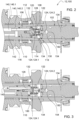
- Figure 3 shows a schematic representation of a power take-off shaft system 12 according to the invention, in particular parts of the power take-off shaft system 12 with the first piston 110 in the first position.
- the power take-off shaft system 12 shown essentially corresponds to the one shown in the Figures 1 and 2 shown PTO system, so that only the differences will be discussed below.
- the piston bore 126 is designed as a first chamber 160. If the first chamber 160 fills with the pressurized fluid, the first piston 110 is moved into the first position.
- the first return element 132 preloads the second piston element 122 in such a way that the first piston 110 can be adjusted back into the neutral position by means of the first return element 132.
- the second return element 134 can also preload the third piston element 124 in such a way that the first piston 110 can also be adjusted to the neutral position by means of the second return element 134.
- the power take-off shaft stub 104 is arranged with the first stub end 150 with the first profile and the first toothing in the socket 102, wherein the recess 154 on the first stub end 150 receives the second piston piece 124.2, which projects into the socket 102.
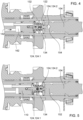
- Figure 4 shows a schematic plan view of the PTO system 12, in particular parts of the PTO system 12, with the first piston 110 in the second position.
- the power take-off shaft system 12 shown essentially corresponds to the one shown in the Figures 1 to 3 shown PTO system 12, so that only the differences will be discussed below.
- the pressurized fluid can be guided in the second fluid feed bore 142 via the output shaft 100 into the volume between the first piston 110 and the base of the valve bore 108, which is designed as a second chamber 162. If the second chamber 162 fills with the pressurized fluid, the first piston 110 is moved into the second position.
- the first return element 132 preloads the first and second piston elements 120, 122, but in particular the first piston element 120, such that the first piston 110 can be adjusted back into the neutral position by means of the first piston element 120 preloaded via the first return element 132.
- the second return element 134 can additionally preload the third piston element 124 such that the first piston 110 can also be adjusted back into the neutral position by means of the second return element 134.
- Figure 5 shows a schematic plan view of the PTO system 12, in particular parts of the PTO system 12, with the first piston 110 in the neutral position and a blocked second position.
- the power take-off shaft system 12 shown essentially corresponds to the one shown in the Figures 1 to 4 shown PTO system 12, so that only the differences will be discussed below.
- the main difference to the PTO system shown in the Figures 1 to 4 shown PTO systems 12 is that the PTO stub 104 with the second stub end 152 with the second profile and the second toothing is arranged in the socket 102, wherein the second piston piece 124.2 protruding into the socket 102 is adjusted from the second stub end 152 in the direction of the first piston piece and along an axis of the third piston element 124.
- the second return element 134 preloads the third piston element 124, and thus also the second piston 118 and its components as a whole, in such a way that an adjustment of the first piston 110 into the second position by means of the second piston 118 can be or is blocked.
Landscapes
- Engineering & Computer Science (AREA)
- General Engineering & Computer Science (AREA)
- Mechanical Engineering (AREA)
- Life Sciences & Earth Sciences (AREA)
- Physics & Mathematics (AREA)
- Fluid Mechanics (AREA)
- Soil Sciences (AREA)
- Environmental Sciences (AREA)
- Arrangement And Driving Of Transmission Devices (AREA)
- Transmission Devices (AREA)
Applications Claiming Priority (2)
| Application Number | Priority Date | Filing Date | Title |
|---|---|---|---|
| DE102019215057.8A DE102019215057A1 (de) | 2019-09-30 | 2019-09-30 | Zapfwellensystem und landwirtschaftliches Fahrzeug |
| EP20198655.1A EP3798038B1 (fr) | 2019-09-30 | 2020-09-28 | Système de prose de force et véhicule agricole |
Related Parent Applications (2)
| Application Number | Title | Priority Date | Filing Date |
|---|---|---|---|
| EP20198655.1A Division-Into EP3798038B1 (fr) | 2019-09-30 | 2020-09-28 | Système de prose de force et véhicule agricole |
| EP20198655.1A Division EP3798038B1 (fr) | 2019-09-30 | 2020-09-28 | Système de prose de force et véhicule agricole |
Publications (2)
| Publication Number | Publication Date |
|---|---|
| EP4410079A2 true EP4410079A2 (fr) | 2024-08-07 |
| EP4410079A3 EP4410079A3 (fr) | 2024-08-28 |
Family
ID=72665097
Family Applications (2)
| Application Number | Title | Priority Date | Filing Date |
|---|---|---|---|
| EP24160737.3A Withdrawn EP4410079A3 (fr) | 2019-09-30 | 2020-09-28 | Système de prose de force et véhicule agricole |
| EP20198655.1A Active EP3798038B1 (fr) | 2019-09-30 | 2020-09-28 | Système de prose de force et véhicule agricole |
Family Applications After (1)
| Application Number | Title | Priority Date | Filing Date |
|---|---|---|---|
| EP20198655.1A Active EP3798038B1 (fr) | 2019-09-30 | 2020-09-28 | Système de prose de force et véhicule agricole |
Country Status (2)
| Country | Link |
|---|---|
| EP (2) | EP4410079A3 (fr) |
| DE (1) | DE102019215057A1 (fr) |
Citations (1)
| Publication number | Priority date | Publication date | Assignee | Title |
|---|---|---|---|---|
| EP2922721A1 (fr) | 2012-11-23 | 2015-09-30 | Valtra Oy Ab | Transmission à rapports multiples de prise de force pour tracteur agricole |
Family Cites Families (7)
| Publication number | Priority date | Publication date | Assignee | Title |
|---|---|---|---|---|
| US3352165A (en) * | 1965-10-04 | 1967-11-14 | Case Co J I | Two-speed power-take-off drive |
| DE2802677C2 (de) * | 1978-01-21 | 1983-12-15 | Zahnradfabrik Friedrichshafen Ag, 7990 Friedrichshafen | Zapfwellenanordnung, insbesondere für Schlepper, mit Umschaltung zwischen zwei Drehzahlbereichen |
| US4271942A (en) * | 1978-10-02 | 1981-06-09 | Allis-Chalmers Corporation | Two-speed power take-off |
| US4287778A (en) * | 1979-12-26 | 1981-09-08 | Allis-Chalmers Corporation | Hydraulic valve for two-speed power take-off drive |
| FI75118C (fi) * | 1986-04-28 | 1988-05-09 | Valmet Oy | Kraftuttagningsapparatur foer traktor. |
| US5667330A (en) * | 1995-11-28 | 1997-09-16 | Case Corporation | Quick-connect mechanism for releasably retaining a power take-off shaft within an output shaft hub |
| US7874222B2 (en) * | 2007-04-19 | 2011-01-25 | Deere & Company | Two-speed PTO stub shaft exchange improvements |
-
2019
- 2019-09-30 DE DE102019215057.8A patent/DE102019215057A1/de active Pending
-
2020
- 2020-09-28 EP EP24160737.3A patent/EP4410079A3/fr not_active Withdrawn
- 2020-09-28 EP EP20198655.1A patent/EP3798038B1/fr active Active
Patent Citations (1)
| Publication number | Priority date | Publication date | Assignee | Title |
|---|---|---|---|---|
| EP2922721A1 (fr) | 2012-11-23 | 2015-09-30 | Valtra Oy Ab | Transmission à rapports multiples de prise de force pour tracteur agricole |
Also Published As
| Publication number | Publication date |
|---|---|
| EP3798038B1 (fr) | 2024-04-10 |
| EP3798038A1 (fr) | 2021-03-31 |
| EP4410079A3 (fr) | 2024-08-28 |
| DE102019215057A1 (de) | 2021-04-01 |
Similar Documents
| Publication | Publication Date | Title |
|---|---|---|
| EP1293113B1 (fr) | Système de commande d'entraînement d'une prise de force d'un véhicule agricole | |
| DE102008048276B4 (de) | Lenkvorrichtung | |
| EP1293697B1 (fr) | Procédure et dispositif de commande d'embrayage | |
| DE1183295B (de) | Vorrichtung zur Lage- und Arbeitswiderstandssteuerung an Ackerschleppern mit elektronisch gesteuerter Hydraulikanlage | |
| DE10000110B4 (de) | Hydrostatischer Fahrzeugantrieb mit Steuerungseinrichtung und Steuerungseinrichtung für hydrostatische Antriebe | |
| DE102014206234B4 (de) | Fahrzeug mit Bodenbearbeitungsgerät und Antriebsschlupfregelung | |
| EP1270306B1 (fr) | Commande de démarrage et d'arrêt d'une prise de force d'un véhicule agricole | |
| DE1457696A1 (de) | Regelhydraulik fuer Kraftheber von Ackerschleppern | |
| EP3798037B1 (fr) | Système de prise de force et véhicule agricole | |
| EP3798038B1 (fr) | Système de prose de force et véhicule agricole | |
| DE19945853A1 (de) | Einrichtung zur Steuerung der Arbeitstiefe eines Bodenbearbeitungsgeräts, insbesondere eines Pfluges | |
| DE3438353A1 (de) | Hydraulische einrichtung fuer ein landwirtschaftliches arbeitsfahrzeug, insbesondere traktor | |
| DE10033811B4 (de) | Schalteinrichtung | |
| DE10039600A1 (de) | Mehrschariger Drehpflug | |
| DE3321443A1 (de) | Vibrationswalze mit leistungsbegrenzungsvorrichtung | |
| AT512982B1 (de) | Anbaugerät mit Stellaktor | |
| DE2751449B1 (de) | Vorrichtung zur Lage- und/oder Arbeitstiefenregelung an landwirtschaftlichen Maschinen,insbesondere fuer mit Ackerschleppern gekuppelte Anbaugeraete | |
| EP0241747B1 (fr) | Dispositif de levage régulateur électro-hydraulique | |
| DE2407925C2 (de) | Steuervorrichtung für eine Kraftübertragungseinrichtung an einem landwirtschaftlichen Schlepper | |
| DE3342007C2 (de) | Regeleinrichtung für ein Hubwerk bei einer Zugmaschine mit Übersetzungsgetriebe | |
| DE3411672A1 (de) | Getriebe | |
| EP4545803A1 (fr) | Agencement hydraulique et véhicule utilitaire | |
| DE102023129650A1 (de) | Hydraulische Anordnung und Nutzfahrzeug | |
| EP3228171A1 (fr) | Installation hydraulique | |
| DE102018117560B4 (de) | Vorrichtung zur Drehmomentübertragung |
Legal Events
| Date | Code | Title | Description |
|---|---|---|---|
| PUAI | Public reference made under article 153(3) epc to a published international application that has entered the european phase |
Free format text: ORIGINAL CODE: 0009012 |
|
| STAA | Information on the status of an ep patent application or granted ep patent |
Free format text: STATUS: THE APPLICATION HAS BEEN PUBLISHED |
|
| REG | Reference to a national code |
Ref country code: DE Ref legal event code: R079 Free format text: PREVIOUS MAIN CLASS: A01B0071060000 Ipc: B60K0017280000 |
|
| PUAL | Search report despatched |
Free format text: ORIGINAL CODE: 0009013 |
|
| AC | Divisional application: reference to earlier application |
Ref document number: 3798038 Country of ref document: EP Kind code of ref document: P |
|
| AK | Designated contracting states |
Kind code of ref document: A2 Designated state(s): AL AT BE BG CH CY CZ DE DK EE ES FI FR GB GR HR HU IE IS IT LI LT LU LV MC MK MT NL NO PL PT RO RS SE SI SK SM TR |
|
| AK | Designated contracting states |
Kind code of ref document: A3 Designated state(s): AL AT BE BG CH CY CZ DE DK EE ES FI FR GB GR HR HU IE IS IT LI LT LU LV MC MK MT NL NO PL PT RO RS SE SI SK SM TR |
|
| RIC1 | Information provided on ipc code assigned before grant |
Ipc: F16D 11/00 20060101ALN20240719BHEP Ipc: F16H 63/30 20060101ALI20240719BHEP Ipc: A01B 71/06 20060101ALI20240719BHEP Ipc: F16D 21/04 20060101ALI20240719BHEP Ipc: F16D 25/061 20060101ALI20240719BHEP Ipc: B60K 17/28 20060101AFI20240719BHEP Ipc: F16H 3/089 20060101ALN20240719BHEP |
|
| STAA | Information on the status of an ep patent application or granted ep patent |
Free format text: STATUS: THE APPLICATION HAS BEEN WITHDRAWN |
|
| 18W | Application withdrawn |
Effective date: 20250220 |