EP4410432A1 - Dérivation de puissance pour un dispositif de broyage - Google Patents
Dérivation de puissance pour un dispositif de broyage Download PDFInfo
- Publication number
- EP4410432A1 EP4410432A1 EP23154933.8A EP23154933A EP4410432A1 EP 4410432 A1 EP4410432 A1 EP 4410432A1 EP 23154933 A EP23154933 A EP 23154933A EP 4410432 A1 EP4410432 A1 EP 4410432A1
- Authority
- EP
- European Patent Office
- Prior art keywords
- motor
- hydraulic
- shaft
- transmission
- synchronous
- Prior art date
- Legal status (The legal status is an assumption and is not a legal conclusion. Google has not performed a legal analysis and makes no representation as to the accuracy of the status listed.)
- Pending
Links
Images


Classifications
-
- B—PERFORMING OPERATIONS; TRANSPORTING
- B02—CRUSHING, PULVERISING, OR DISINTEGRATING; PREPARATORY TREATMENT OF GRAIN FOR MILLING
- B02C—CRUSHING, PULVERISING, OR DISINTEGRATING IN GENERAL; MILLING GRAIN
- B02C18/00—Disintegrating by knives or other cutting or tearing members which chop material into fragments
- B02C18/06—Disintegrating by knives or other cutting or tearing members which chop material into fragments with rotating knives
- B02C18/16—Details
- B02C18/24—Drives
Definitions
- the present invention relates to a device with a power split for driving a rotor shaft of a shredding device for shredding material, in particular in the form of waste products.
- the present invention further relates to a shredding device with such a device.
- the rotor shaft is typically driven by a drive shaft that is connected to the drive shaft via a shaft coupling.
- the drive shaft is driven by a motor via a gearbox.
- Hydraulic gearboxes with an adjustable hydraulic pump and adjustable hydraulic motor are often used.
- Such hydraulic gearboxes offer the advantage of being able to increase the drive torque when the load is required by reducing the speed and increasing the hydraulic pressure.
- By increasing the drive torque it is possible to largely prevent the rotor shafts from blocking or reversing and thus interrupting the shredding process, i.e. a loss in throughput, and the risk of the shafts rotating backwards. to avoid a lower quality crushing result, which negatively affects the overall result with regard to the desired granulate size.
- a device for driving (at least) one rotor shaft (shredding shaft) of a shredding device according to claim 1.
- This device comprises a first motor, a hydraulic transmission (hydrostatic transmission) and a synchronous transmission (synchronized transmission) which is different from the hydraulic transmission and is designed to drive at least one rotor shaft or at least one drive shaft connected to a rotor shaft.
- the first motor and the hydraulic transmission are connected to the synchronous transmission.
- this connection can be a direct connection or a connection via another component. All operating parameters of the components of the device can be regulated/controlled by a central control unit.
- This device allows an overall energy-efficient provision of a torque for one or more shafts of a crushing device, whereby a direct drive using the first motor with high energy efficiency (part of a first power branch) is combined with the advantages of a hydraulic transmission (part of a second power branch) to increase the torque provided as the load on the one or more shafts increases, without the need for the use of complicated, specially designed power-split transmissions.
- the torque provided by the motor can be combined with the torque provided by the hydraulic transmission in a cost-effective manner by means of a relatively simply designed synchronous transmission and transmitted to the one or more shafts. If there is only a relatively small or medium load on the one or more shafts, i.e. only a relatively small or medium torque is required, this torque can, for example, be provided by the first motor alone, and if the load increases, for example if a load threshold is exceeded, the hydraulic transmission can be switched on to provide additional torque.
- the device may further comprise a first reduction gear, which is different from the hydraulic gear, and/or a second reduction gear, which is different from the first reduction gear and the hydraulic gear.
- the first motor is connected to the first reduction gear and/or the hydraulic gear is connected to the second reduction gear, and the first and/or the second reduction gear are connected to the synchronous gear.
- the first and second reduction gears serve to adapt the speed supplied by the first motor and the hydraulic gear to the speed required for the one or more shafts (drive shafts and rotor shafts) and they can be formed in one structural unit.
- the device can further comprise a direct drive and/or a clutch, via which the first motor is connected to the synchronous gear. If the first synchronous gear is provided, the first motor can be connected to this first synchronous gear via the direct drive and/or the clutch.
- the clutch can be arranged between the direct drive and the first reduction gear and it can be designed as an overload clutch, which in particular in the event of a sudden total blockage of a rotor shaft of a shredding device, which comprises the device, disengages the motor/direct drive.
- the clutch can be a switchable clutch in order to disengage the first motor/direct drive in the event that it is necessary to reverse the rotor shaft by means of the switchable clutch.
- the direct drive can be a belt drive, for example.
- the first motor can be connected to the first reduction gear via a cardan shaft.
- the first motor can be directly connected to the first reduction gear/built on the reduction gear. If the first motor offers the speed required by the shaft to be driven, it can be directly connected to the synchronous gear without a reduction gear.
- the first motor is a first electric motor. Electric motors are characterized by both high energy efficiency and the absence of CO2 emissions.
- the first motor can be designed as a combustion engine (for example a diesel engine), for example for applications in which no suitable power grid is available.
- the device can comprise a first frequency converter which is designed to regulate or control the speed and/or the direction of rotation of the first electric motor, so that the operation of the motor can be adapted to changing operating conditions (for example full load or reversing shafts) in a simple and quick manner.
- a first frequency converter which is designed to regulate or control the speed and/or the direction of rotation of the first electric motor, so that the operation of the motor can be adapted to changing operating conditions (for example full load or reversing shafts) in a simple and quick manner.
- the first motor of the device is connected to the hydraulic transmission in order to operate it.
- the hydraulic transmission can thus comprise a hydraulic pump that can be operated by the first motor and a hydraulic motor connected to the hydraulic pump, which is optionally connected to the synchronous transmission via the second reduction gear.
- the device can comprise a second motor that is different from the first motor and is connected to the hydraulic transmission.
- This second motor can be provided exclusively to operate a hydraulic pump included in the hydraulic transmission in order to supply a hydraulic motor of the hydraulic transmission with a hydraulic fluid.
- the second motor can also be designed as an electric motor.
- the device can comprise a second frequency converter that is designed to regulate or control the speed and/or the direction of rotation of the second electric motor.
- a shredding device which comprises a material receiving space, a rotor shaft arranged in the material receiving space and a device according to one of the preceding claims.
- the rotor shaft is connected to the synchronous gear of the device, for example via a drive shaft and a shaft coupling, for driving the rotor shaft.
- the shredding device can in particular be a relatively large and heavy shredding device for shredding, for example, wood, plastic or textile waste products or other industrial, agricultural and domestic waste weighing several tons.
- the shredding device can here be a single-shaft or multi-shaft shredder, in particular a vertical shredder.
- the method may further comprise, in a fourth operating state following the third operating state, the step of operating the hydraulic transmission with a displacement volume of a hydraulic motor of the hydraulic transmission that is increased compared to the third operating state and adjusting the speed of the first motor to the speed of the hydraulic motor of the hydraulic transmission.
- a shredding process of a material to be shredded can be regulated or controlled very variably and precisely according to the load applied to the rotor shaft(s), i.e. according to the total torque required to shred a material to be shredded.
- the present invention provides a device with a power split for driving a rotor shaft of a shredding device via a synchronous gear.
- the device only requires relatively simply constructed components and enables energy-efficient continuous operation of a shredding device equipped with the device with a relatively high throughput and thus relatively low costs per unit of time.
- the power split is carried out using standard components that can be flexibly put together for small machine series, without expensive special mechanical components such as a power-split gear.
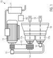
- FIG. 1 An embodiment of a device 10 according to the invention for driving a rotor shaft of a comminution device is shown in Figure 1 illustrated.
- the device 10 comprises an electric motor (or alternatively an internal combustion engine controlled/regulated in some other way) 12 controlled/regulated via a frequency converter 11.
- the clutch 14 can be designed as an overload clutch, which serves as a safeguard in particular in the event of a sudden total blockage of a rotor shaft of a shredding device comprising the device 10 due to a foreign substance.
- the electric motor 12 can be mounted directly on the reduction gear 17a, or it can be connected to the reduction gear 17a via a cardan shaft. Furthermore, the electric motor 12 is connected to a hydraulic pump 15 of a hydraulic transmission, which feeds a hydraulic motor 16 of the hydraulic transmission. A change in the torque requirement can be responded to by changing the hydraulic pressure of the hydraulic fluid supplied by the hydraulic pump 15. The speed of the hydraulic motor 16 can be regulated/controlled via the volume of the hydraulic fluid supplied by the hydraulic pump 15 or the displacement volume of the hydraulic motor 16.
- the hydraulic motor 16 is connected to a second reduction gear 17b.
- the hydraulic gear can be equipped with an overpressure protection device (for example a pressure relief valve).
- the reduction gears 17a and 17b can be designed in one structural unit.
- the reduction gears 17a and 17b can be designed as planetary gears.
- the electric motor 12, the direct drive 13, the clutch 14 and the reduction gear 17a represent a first power branch of the device 10.
- the hydraulic transmission with the hydraulic pump 15 and the hydraulic motor 16 and the reduction gear 17b represent a second power branch of the device 10.
- the reduction gears 17a and 17b are connected to a synchronous gear (synchronized gear) 18, which is designed to drive one or more shafts 19, such as one or more rotor shafts (crushing shafts) or one or more drive shafts, each of which is connected to a rotor shaft via a shaft coupling.
- a synchronous gear synchronized gear
- All control parameters of the device 10 can be controlled via a control unit RS.
- the control unit RS can control the electric motor 12, which can be designed as an asynchronous or synchronous motor, and the frequency converter 1, with which the speed and direction of rotation of the electric motor 12 can be controlled.
- the control unit RS can control the clutch 14, which can provide overload protection and/or can switch the direct drive 13 on and off in a controlled manner.
- the control unit RS can control the hydraulic pump 15, which can be set between 0 delivery volume and a maximum delivery volume in both directions of rotation.
- the control unit RS can control the hydraulic motor 16, which can be controlled via oil pressure parameters and the displacement volume (swivel angle). speed and torque can be regulated/controlled.
- the control unit RS can adjust the reduction gears 17a and 17b to the required shaft speeds.
- the torque required by the rotor shaft (or shafts) can be provided to a certain extent (in the lower and medium load range) with the highest efficiency in the direct drive, and the hydraulic gear with the additional torque can only be switched on when load peaks occur.
- the displacement of the hydraulic motor 16 can be regulated/controlled to the maximum, which reduces the speed to the minimum. So that the power branch of the electric motor/drive can also be used when the speed is reduced, the electric motor 12 can be regulated to the speed of the hydraulic motor 16 via the frequency converter 11.
- the RS control unit can regulate/control the various components depending on the load that occurs.
- the load that occurs can be determined using measured torques, current values or hydraulic pressure values, or a combination of these. Different machine operation goals can be pursued using the RS control unit.
- the control can be regulated/controlled to meet the various needs of the machine operator, for example towards the highest energy efficiency, maximum power or highest throughput.
- An automatic torque regulation/control and speed regulation/control of the motor can be provided.
- the feed material, feed quantity, discharge quantity, etc. can be taken into account here.
- the shredding device equipped with the device 10 can be operated efficiently with a relatively low speed ( ⁇ nominal speed) of the shaft 19 if the feed volume is small and a continuous discharge is to be achieved, because, for example, a further unit, for example a screening system, can be operated more efficiently with it.
- the direct drive must be provided by means of the switchable clutch 14 can be deactivated.
- the maximum torque in reversing mode is thus determined by the maximum achievable torque of the hydraulic transmission.
- FIG. 2 A further embodiment of a device 20 according to the invention for driving a rotor shaft of a comminution device is shown in Figure 2
- the embodiment shown in Figure 2 has two motors 22a and 22b (for example electric motors), of which the first motor 22a is connected to a reduction gear 27a via a direct drive 22 and a clutch 23, and the second motor 22b operates a hydraulic pump 25 of a hydraulic transmission, which feeds a hydraulic motor 26 of the hydraulic transmission.
- the hydraulic motor 26 is connected to a reduction gear 27b.
- the first (electric) motor 22a is controlled/regulated using a frequency converter 11a
- the second (electric) motor 22b is controlled/regulated using a further frequency converter 11b.
- control unit RS shown has a corresponding control unit RS (which can of course also control the further frequency converter 11b or the second motor 22b).
- the reduction gears 27a and 27b can be designed in one structural unit.
- the reduction gears 27a and 27b can be designed as planetary gears.
- the reduction gears 27a and 27b are connected to a synchronous gear 28 which is designed to drive one or more shafts 29, such as one or more rotor shafts or one or more drive shafts, each of which is connected to a rotor shaft via a shaft coupling.
- the torques provided by the first motor 22a and the hydraulic gear, which are input via the reduction gears 27a and 27b, are transmitted to the one or more shafts 29 via this synchronous gear 28.
- the second motor 22b for operating the hydraulic pump 25 of the hydraulic transmission does not, in principle, have to be a speed-controlled motor.
- the speed control and reversal of the direction of rotation can also be carried out by means of a controlled hydraulic pump.
- synchronous gears 18 and 28 of the device 10 and 20 Via the synchronous gears 18 and 28 of the device 10 and 20, more than one shaft can be driven.
- switchable gearing in the synchronous gear 18 or 28 a shift from one gear to outside the tooth mesh.
- the maximum total torque is divided as required between the (shredding) shafts 19 or 29.
- one (shredding) shaft 19 or 29 is supplied with the available torque directly via the motor 12 or 22 and the direct drive 13 or 23, and the second (shredding) shaft 19 or 29 is supplied with the available torque via the hydraulic gear.
- the first reduction gear 17a, 27a in device 10 and/or the second reduction gear 17b, 27b can be dispensed with if the appropriate speed for driving the shaft(s) is provided by the first motor 12, 22a or the hydraulic motor 16, 26 of the hydraulic transmission.
- Figure 3 shows a synchronous transmission that can be used in a device for driving a rotor shaft of a crushing device according to an embodiment.
- the Figure 1 shown synchronous gear 18 of the device 10 or the one in Figure 2 shown synchronous gear 28 of the device 20 which in Figure 3 shown synchronous transmission.
- the synchronous transmission comprises two connection points (210, 220), one for the direct drive/motor and the other for the hydraulic transmission (cf. Figures 1 and 2 ).
- Reduction gears can be connected directly at the connection points (210, 220) (see Figures 1 and 2 ), which may be required for the reduction of the speeds, as described above.
- a synchronous stage is required to combine the drives/torques, as in Figure 3 shown as an example as a spur gear with the gears (230, 240).
- the gear diameters of the gears (230, 240) do not necessarily have to be the same size.
- any other gear stage that combines the two power branches can be used as an alternative.
- connection flanges 250 and 260 for connecting shafts 270 and 280 to be driven.
- the synchronous stage can now be duplicated as required in order to drive any number of shafts simultaneously.
- the connection flange 260 is omitted.
- Figure 3 shows an exemplary design of the synchronous gear for driving exactly two shafts 270 and 280, which operate synchronously at the same speed with the help of the synchronous gear.
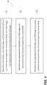
- Figure 4 illustrates a method 30 for operating a device for driving a rotor shaft of a comminution device according to an embodiment of the invention.
- the device comprises a first motor, a hydraulic transmission with a hydraulic pump and a hydraulic motor, optionally a first reduction gear that is different from the hydraulic transmission, optionally a second reduction gear that is different from the first reduction gear and the hydraulic transmission, and a synchronous transmission that is different from the hydraulic transmission and the first and second reduction gear and is designed to drive at least one rotor shaft or at least one drive shaft connected to a rotor shaft.
- the first motor is connected (optionally via the first reduction gear) to the synchronous transmission
- the hydraulic transmission is connected (optionally via the second reduction gear) to the synchronous transmission.
- the device can, for example, have the configuration shown in Figure 1 shown device 10 or the one in Figure 2
- the hydraulic pump of the hydraulic transmission is operated either by the first motor (see the device 20 shown in Figure 1 shown embodiment of the device 10) or by an additional second motor (see the embodiment shown in Figure 2 shown embodiment of the device 20).
- the first motor of the device in a first operating state, is operated to transmit a torque via the first reduction gear (if present) and the synchronous gear to at least one shaft connected to the synchronous gear (rotor shaft or drive shaft for a rotor shaft) S31 when a relatively small or medium load is applied to this at least one shaft.
- this first operating state no significant additional torque is transmitted to the at least one shaft connected to the synchronous gear via the hydraulic gear.
- the hydraulic gear is disengaged in this operating state or the hydraulic pump of the hydraulic gear is not delivering.
- the hydraulic pump supplies a hydraulic/pressure fluid (hydraulic oil) to the hydraulic motor, which operates with a relatively small displacement volume and hydraulic pressure in this second operating state.
- a torque that is higher than in the second operating state is provided by the hydraulic transmission S33, i.e. the hydraulic pressure from the hydraulic pump is further increased and the hydraulic motor operates in this third operating state with a relatively large displacement volume that is higher than in the second operating state.
- the torque transmitted to the drive or rotor shaft via the synchronous transmission is thereby further increased compared to the second operating state.
- the hydraulic pressure can be increased up to a given maximum value at which the maximum torque is reached with the maximum speed of the at least one drive or rotor shaft.
- This maximum torque with the maximum speed of the at least one drive or rotor shaft can be further increased by reducing the speed of the at least one drive or rotor shaft if the displacement volume of the hydraulic motor can be increased even further when the maximum hydraulic pressure and maximum delivery volume of the hydraulic pump are reached (when the hydraulic motor has the maximum displacement volume, it provides the minimum speed). If the speed of the drive or rotor shaft is reduced, it is necessary that the first motor is regulated/controlled to the speed of the hydraulic motor in order to continue to be used for torque transmission.
- the device according to the invention is suitable for driving a rotor shaft of a comminution device, for example the one in Figure 1 shown 10 or the one in Figure 2 shown device 20, in a crushing device for Shredding wood, plastic or textile waste products or other industrial, agricultural and domestic waste.
- a shredding device can, for example, weigh between 10 and 20 tons and have a drive power of 75 to 650 kW and have one or more rotor shafts that operate at, for example, 20 to 40 revolutions per minute.
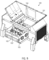
- FIG. 5 An exemplary embodiment of a shredding device 100 in the form of a twin-shaft shredder is shown in a maintenance state in Figure 5 shown.
- the shredding device 100 shown comprises a shaft coupling device 10.
- the shredding device 100 comprises a material receiving space 101 into which material to be shredded can be filled.
- the material receiving space 101 can be fed with the material to be shredded by wheel loaders, forklifts or conveyor belts via a hopper.
- the material to be shredded is shredded by means of rotor shafts 102, 102 ⁇ , which are equipped with knives.
- a non- Figure 5 The pusher shown can be provided to press the material to be shredded towards the rotor shafts 102, 102 ⁇ .
- the rotor shafts 102, 102 ⁇ are moved out of the material receiving space 101 on a carrier cassette 103.
- the shredding device 100 comprises a drive shaft for each of the two rotor shafts 102, 102 ⁇ , the shaft hubs 104 of which can be positioned inside or outside the material receiving space 101.
- the shredding device 100 further comprises a device for driving a rotor shaft of a shredding device.
- the device comprises a first motor, a hydraulic transmission with a hydraulic pump and a hydraulic motor, optionally a first reduction gear that is different from the hydraulic transmission, optionally a second reduction gear that is different from the first reduction gear (if present) and the hydraulic transmission, and a synchronous transmission that is different from the hydraulic transmission and the first and second reduction gear (if present) and is designed to drive at least one rotor shaft or at least one drive shaft connected to a rotor shaft.
- the synchronous transmission is connected to the drive shafts assigned to the two rotor shafts 102, 102' for driving the same.
- the first motor is connected to the synchronous transmission (if necessary via the first reduction gear), and the hydraulic transmission is connected to the synchronous transmission (if necessary via the second reduction gear).
- the device for driving a rotor shaft of a crushing device included in the crushing device 100 is the device shown in Figure 1 shown device 10 or the one in Figure 2 device shown 20.
Landscapes
- Engineering & Computer Science (AREA)
- Food Science & Technology (AREA)
- Crushing And Pulverization Processes (AREA)
- Crushing And Grinding (AREA)
Priority Applications (4)
| Application Number | Priority Date | Filing Date | Title |
|---|---|---|---|
| EP23154933.8A EP4410432A1 (fr) | 2023-02-03 | 2023-02-03 | Dérivation de puissance pour un dispositif de broyage |
| PCT/EP2023/080793 WO2024160400A1 (fr) | 2023-02-03 | 2023-11-06 | Division de puissance pour un dispositif de broyage |
| KR1020257029195A KR20250143806A (ko) | 2023-02-03 | 2023-11-06 | 분쇄 디바이스에 대한 동력 분할 |
| CN202380093013.5A CN120826281A (zh) | 2023-02-03 | 2023-11-06 | 用于粉碎设备的功率分流 |
Applications Claiming Priority (1)
| Application Number | Priority Date | Filing Date | Title |
|---|---|---|---|
| EP23154933.8A EP4410432A1 (fr) | 2023-02-03 | 2023-02-03 | Dérivation de puissance pour un dispositif de broyage |
Publications (1)
| Publication Number | Publication Date |
|---|---|
| EP4410432A1 true EP4410432A1 (fr) | 2024-08-07 |
Family
ID=85174027
Family Applications (1)
| Application Number | Title | Priority Date | Filing Date |
|---|---|---|---|
| EP23154933.8A Pending EP4410432A1 (fr) | 2023-02-03 | 2023-02-03 | Dérivation de puissance pour un dispositif de broyage |
Country Status (4)
| Country | Link |
|---|---|
| EP (1) | EP4410432A1 (fr) |
| KR (1) | KR20250143806A (fr) |
| CN (1) | CN120826281A (fr) |
| WO (1) | WO2024160400A1 (fr) |
Citations (4)
| Publication number | Priority date | Publication date | Assignee | Title |
|---|---|---|---|---|
| US4721257A (en) * | 1986-12-04 | 1988-01-26 | Williams Patent Crusher And Pulverizer Company | Rotary shredding apparatus |
| US4793561A (en) * | 1982-05-24 | 1988-12-27 | Mac Corporation Of America | Speed-responsive reversing hydraulic drive for rotary shredder |
| EP1593435A1 (fr) * | 2004-04-30 | 2005-11-09 | Edi Bondioli | Dispositif de réduction pour des outils de broyeur et broyeur avec un tel dispositif |
| EP3251748A1 (fr) * | 2016-06-01 | 2017-12-06 | Manuel Lindner | Broyeur de déchets mobile doté d'un entrainement hybride parallèle |
-
2023
- 2023-02-03 EP EP23154933.8A patent/EP4410432A1/fr active Pending
- 2023-11-06 WO PCT/EP2023/080793 patent/WO2024160400A1/fr not_active Ceased
- 2023-11-06 KR KR1020257029195A patent/KR20250143806A/ko active Pending
- 2023-11-06 CN CN202380093013.5A patent/CN120826281A/zh active Pending
Patent Citations (4)
| Publication number | Priority date | Publication date | Assignee | Title |
|---|---|---|---|---|
| US4793561A (en) * | 1982-05-24 | 1988-12-27 | Mac Corporation Of America | Speed-responsive reversing hydraulic drive for rotary shredder |
| US4721257A (en) * | 1986-12-04 | 1988-01-26 | Williams Patent Crusher And Pulverizer Company | Rotary shredding apparatus |
| EP1593435A1 (fr) * | 2004-04-30 | 2005-11-09 | Edi Bondioli | Dispositif de réduction pour des outils de broyeur et broyeur avec un tel dispositif |
| EP3251748A1 (fr) * | 2016-06-01 | 2017-12-06 | Manuel Lindner | Broyeur de déchets mobile doté d'un entrainement hybride parallèle |
Also Published As
| Publication number | Publication date |
|---|---|
| CN120826281A (zh) | 2025-10-21 |
| KR20250143806A (ko) | 2025-10-02 |
| WO2024160400A1 (fr) | 2024-08-08 |
Similar Documents
| Publication | Publication Date | Title |
|---|---|---|
| EP2283253B1 (fr) | Organe de transmission à superposition avec arbres d accouplement | |
| DE69402410T2 (de) | Stufenlos regelbares getriebe | |
| DE10333359B3 (de) | Zerkleinerungsvorrichtung für Abfälle | |
| EP2170517B1 (fr) | Broyeur à cylindres et procédé pour le broyage d'une matière à broyer | |
| DE2525888B2 (de) | Leistungsverzweigende Getriebeanordnung | |
| EP2280116A1 (fr) | Triturateur doté d'un moteur à couple | |
| DE10319252A1 (de) | Stufenlos leistungsverzweigtes Getriebe | |
| WO2013143652A1 (fr) | Mécanisme d'entraînement dans un engin automoteur de chantier et procédé de réglage d'un rapport de vitesse de rotation dans un tel mécanisme d'entraînement | |
| EP2736646B1 (fr) | Dispositif de broyage | |
| EP3869067A1 (fr) | Machine de traitement du sol avec une transmission pourvue de boîte de vitesses à deux rapports en deux pièces à des ratios de transmission seulement légèrement différents | |
| DE19621391B4 (de) | Ballenpresse für landwirtschaftliches Erntegut | |
| EP1749576B1 (fr) | Désintégrateur avec motor electrique a convertisseur de fequence monte en amont et un train épicycloidal | |
| DE2409914A1 (de) | Stufenlos regelbares getriebe | |
| WO2016012317A1 (fr) | Dispositif de transmission de puissance | |
| DE102007004274A1 (de) | Gasturbinentriebwerk, insbesondere Flugtriebwerk | |
| WO2024160400A1 (fr) | Division de puissance pour un dispositif de broyage | |
| EP1632131B1 (fr) | Système d'entraînement d'un dispositif d'alimentation pour une machine agricole | |
| DE102011106123A1 (de) | Reversierbarer Antrieb | |
| EP2215381B1 (fr) | Système modulaire pour boîte de vitesses hydrostatique-mécanique couplable sous charge | |
| DE102011000749A1 (de) | Walzenmühle | |
| DE3416506A1 (de) | Antriebsanordnung fuer zweirotorige prallbrecher | |
| EP3289244B1 (fr) | Engin de travail à repartition de puissance | |
| DE202013004051U1 (de) | Getriebe für Zerkleinerungsmaschine | |
| DE102012004984B4 (de) | Vorrichtung zum Zerkleinern von Stückgut | |
| EP3909683A1 (fr) | Utilisation d'un système d'entraînement pour un dispositif de broyage |
Legal Events
| Date | Code | Title | Description |
|---|---|---|---|
| PUAI | Public reference made under article 153(3) epc to a published international application that has entered the european phase |
Free format text: ORIGINAL CODE: 0009012 |
|
| STAA | Information on the status of an ep patent application or granted ep patent |
Free format text: STATUS: THE APPLICATION HAS BEEN PUBLISHED |
|
| AK | Designated contracting states |
Kind code of ref document: A1 Designated state(s): AL AT BE BG CH CY CZ DE DK EE ES FI FR GB GR HR HU IE IS IT LI LT LU LV MC ME MK MT NL NO PL PT RO RS SE SI SK SM TR |
|
| STAA | Information on the status of an ep patent application or granted ep patent |
Free format text: STATUS: REQUEST FOR EXAMINATION WAS MADE |
|
| 17P | Request for examination filed |
Effective date: 20240820 |
|
| RBV | Designated contracting states (corrected) |
Designated state(s): AL AT BE BG CH CY CZ DE DK EE ES FI FR GB GR HR HU IE IS IT LI LT LU LV MC ME MK MT NL NO PL PT RO RS SE SI SK SM TR |