EP4410460A1 - Marteau perforateur - Google Patents
Marteau perforateur Download PDFInfo
- Publication number
- EP4410460A1 EP4410460A1 EP23154963.5A EP23154963A EP4410460A1 EP 4410460 A1 EP4410460 A1 EP 4410460A1 EP 23154963 A EP23154963 A EP 23154963A EP 4410460 A1 EP4410460 A1 EP 4410460A1
- Authority
- EP
- European Patent Office
- Prior art keywords
- drill
- helix
- drill head
- hammer drill
- conveyor
- Prior art date
- Legal status (The legal status is an assumption and is not a legal conclusion. Google has not performed a legal analysis and makes no representation as to the accuracy of the status listed.)
- Withdrawn
Links
Images


Classifications
-
- B—PERFORMING OPERATIONS; TRANSPORTING
- B28—WORKING CEMENT, CLAY, OR STONE
- B28D—WORKING STONE OR STONE-LIKE MATERIALS
- B28D1/00—Working stone or stone-like materials, e.g. brick, concrete or glass, not provided for elsewhere; Machines, devices, tools therefor
- B28D1/14—Working stone or stone-like materials, e.g. brick, concrete or glass, not provided for elsewhere; Machines, devices, tools therefor by boring or drilling
- B28D1/146—Tools therefor
-
- B—PERFORMING OPERATIONS; TRANSPORTING
- B23—MACHINE TOOLS; METAL-WORKING NOT OTHERWISE PROVIDED FOR
- B23B—TURNING; BORING
- B23B51/00—Tools for drilling machines
- B23B51/0002—Drills with connected cutting heads, e.g. with non-exchangeable cutting heads; Drills with a single insert extending across the rotational axis and having at least two radially extending cutting edges in the working position
-
- B—PERFORMING OPERATIONS; TRANSPORTING
- B23—MACHINE TOOLS; METAL-WORKING NOT OTHERWISE PROVIDED FOR
- B23B—TURNING; BORING
- B23B51/00—Tools for drilling machines
- B23B51/02—Twist drills
-
- B—PERFORMING OPERATIONS; TRANSPORTING
- B23—MACHINE TOOLS; METAL-WORKING NOT OTHERWISE PROVIDED FOR
- B23B—TURNING; BORING
- B23B2251/00—Details of tools for drilling machines
- B23B2251/04—Angles, e.g. cutting angles
- B23B2251/043—Helix angles
- B23B2251/046—Variable
Definitions
- the invention is based on a hammer drill, comprising a shaft section, a drill head at one end of the shaft section and an insertion section at the other end, wherein a conveyor spiral is formed along the shaft section, wherein at least one striking tip or one striking edge is formed on the drill head.
- Such hammer drills are used especially for drilling rock.
- a hammer drill should have the highest possible mining performance in order to enable rapid work, especially in hard rocks such as concrete, for example in the form of reinforced concrete, or granite.
- the object of the present invention is therefore to provide a hammer drill of the type mentioned at the beginning with a particularly high mining performance.
- a hammer drill comprising a shaft section, a drill head at one end of the shaft section and an insertion section at the other end, wherein a conveying spiral is formed along the shaft section, wherein at least one striking tip or one striking edge is formed on the drill head, wherein a spiral is formed on the drill head which opens into the conveying spiral at an angle to a longitudinal axis of the hammer drill.
- drilling dust that is created when rock is mined should be transported away from the drill head.
- the spiral formed on the drill head allows the drilling dust to be actively transported away in the area of the drill head.
- the drilling dust transport capacity can be increased.
- the drilling dust can therefore hinder the mining at the impact tip or the impact edge less. This can improve the overall mining performance. improve.
- the spiral can, for example, open into the conveyor spiral at an angle of at least one degree, for example at an angle between 5 and 75 degrees, relative to the longitudinal axis.
- the spiral and the conveyor spiral can have the same pitch.
- the overall transport capacity can be increased if the conveyor spiral has multiple threads. For example, it can have at least two threads.
- the spiral on the drill head can also have multiple threads. In particular, it can have a number of threads corresponding to the conveyor spiral.
- the threads can each end at an impact edge. Accordingly, the drill head can have an impact edge corresponding to the number of threads.
- the drill head can have at least two, in particular four, five or six, impact edges.
- a higher number of impact edges can help to ensure that the hammer drill does not jam when it hits steel, for example when drilling into reinforced concrete, or at least only in rare cases.
- the drill head can be tapered.
- the drill head can be tapered towards the impact tip or impact edge.
- the diameter of the helix can be smaller than the diameter of the conveyor helix.
- the flow of the drilling dust along the conveyor spiral and/or the spiral can be further improved if at least one pitch of the spiral and/or one pitch of the conveyor spiral varies continuously at least in sections. In particular, local accumulations of drilling dust along the conveyor spiral and/or the spiral can be avoided.
- the drill head can be joined to the shaft section, for example soldered or welded.
- a joining zone between the drill head and the shaft section can be formed in which the drill head and the shaft section contact each other along a contact surface.
- the helix back can be wider or narrower than the helix back of the conveyor helix, at least in one section of the helix.
- a diameter of the drill head can be larger than a largest diameter of the conveyor spiral.
- the drill head can thus protrude beyond the conveyor spiral.
- the drill head can taper from its impact tip or the impact edge towards the conveyor spiral. Friction between the shaft section, in particular the conveyor spiral, and the wall is reduced, so that friction losses due to the rotation of the hammer drill during hammer drilling can be minimized.
- the drill head can comprise a tungsten-containing material, in particular a tungsten carbide and/or a tungsten boride.
- the drill head can thus have a particularly high hardness and/or a particularly good fracture strength.
- the hammer drill can therefore be set up, for example, to transmit high impact pulses along its longitudinal axis to a surface to be worked on.
- high impact energies of 1 J or higher, for example 5 J
- Suitable machine tools, particularly hammer drills often have an electropneumatic drive to generate the impact pulses.
- drilling dust can be produced at a high throughput. The higher the throughput, the more advantageous a high transport capacity is, as can be offered by the hammer drill described above.
- the hammer drill is designed for construction work in building construction and/or civil engineering.
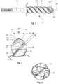
- Fig.1 shows in a side view a hammer drill 10, comprising a shaft section 12, a drill head 14 at one end of the shaft section 12 and an insertion section 16 at the other end.
- a conveying spiral 18 is formed along the shaft section 12.
- FIG.1 the shaft section 12 with its conveyor spiral 18 is shown in shortened form.
- the drill head 14 is made of sintered tungsten carbide. It is conceivable that the sintered tungsten carbide has a cobalt-free binder.
- the drill head 14 is provided with a striking tip 20 and several striking edges 22 , of which Fig.1 each of which is provided with a reference symbol as an example.
- the conveyor spiral 18 has two threads. In alternative embodiments, the conveyor spiral 18 can also have only one or more than two threads. In particularly preferred embodiments, the number of threads of the conveyor spiral 18 can correspond to the number of impact edges 22.
- a helix 24 is formed on the drill head 14.
- the helix 24 opens into the conveyor helix 18 at an angle to a longitudinal axis L of the hammer drill 10.
- Fig.2 shows a side view of a detailed view of the drill head 14 and a section of the conveyor spiral 18.
- the drill head 14 tapers towards its impact edges 22 and its impact tip 20. Accordingly, the helix 24 also tapers from a diameter d1 in a base area of the drill head 14 to a diameter d2 in the area of the impact edges 22.
- a width b1 of a spiral back 26 of the spiral 24 is wider than a width b2 of a conveyor spiral back 28 of the conveyor spiral 18.
- Fig.3 shows a top view of the drill head 14. Due to the oblique to the longitudinal axis L (see Fig.1 ) results in a propeller-shaped geometry of the drill head 14.
- Fig.4 which shows the drill head 14 with its helix 24 and a part of the conveyor helix 18, it can be seen that the helix 24 has the same pitch as the conveyor helix 18.
- the helix 24 forms an angle alpha of 45° to the longitudinal axis L and the conveyor helix 18 forms an angle beta of 45° to the longitudinal axis L.
- Fig.5 shows in a diagram the results of a comparison test of the mining performance of the hammer drill 10 to the mining performance of two other rock drills 100, 200.
- the rock drills 100, 200 differ from the hammer drill 10, among other things, in that their drill heads 114, 214 do not have a spiral that opens into a conveyor spiral 118, 218 at an angle to a longitudinal axis.
- the drill head 214 of the rock drill 200 also has no spiral. Between the drilling dust entry areas 230 on the drill head 214 and a conveyor spiral 218 of the rock drill 200, there are also kinks 232, over which drilling dust sliding past during drilling with the rock drill 200 must also make an abrupt change of direction.
- Drilling performance was measured in the form of drilling speeds in mm/s when drilling into concrete of class C50/60 GK8 at a contact force of 200 N using a hammer drill with a single impact energy of approximately 12 J.
- the hammer drill 10 showed a mining performance increased by more than 25% at approx. 8.5 mm/s compared to approx. 6.7 mm/s for the rock drill 100 and approx. 6.5 mm/s for the rock drill 200.
Landscapes
- Engineering & Computer Science (AREA)
- Mechanical Engineering (AREA)
- Mining & Mineral Resources (AREA)
- Earth Drilling (AREA)
Priority Applications (1)
| Application Number | Priority Date | Filing Date | Title |
|---|---|---|---|
| EP23154963.5A EP4410460A1 (fr) | 2023-02-03 | 2023-02-03 | Marteau perforateur |
Applications Claiming Priority (1)
| Application Number | Priority Date | Filing Date | Title |
|---|---|---|---|
| EP23154963.5A EP4410460A1 (fr) | 2023-02-03 | 2023-02-03 | Marteau perforateur |
Publications (1)
| Publication Number | Publication Date |
|---|---|
| EP4410460A1 true EP4410460A1 (fr) | 2024-08-07 |
Family
ID=85175733
Family Applications (1)
| Application Number | Title | Priority Date | Filing Date |
|---|---|---|---|
| EP23154963.5A Withdrawn EP4410460A1 (fr) | 2023-02-03 | 2023-02-03 | Marteau perforateur |
Country Status (1)
| Country | Link |
|---|---|
| EP (1) | EP4410460A1 (fr) |
Citations (9)
| Publication number | Priority date | Publication date | Assignee | Title |
|---|---|---|---|---|
| FR2124857A5 (fr) * | 1972-01-20 | 1972-09-22 | Vorabbi Luigi | |
| GB2075409A (en) * | 1980-05-09 | 1981-11-18 | Vnii Tugoplavkikh | Drills |
| WO1997006338A1 (fr) * | 1995-08-10 | 1997-02-20 | Black & Decker Inc. | Outil de coupe servant a percer du beton, de l'agglomere ou de la maçonnerie |
| EP1217165A1 (fr) * | 2000-12-22 | 2002-06-26 | DreBo Werkzeugfabrik GmbH | Foret à roche |
| EP0761927B1 (fr) * | 1995-07-29 | 2003-11-26 | Black & Decker Inc. | Mèche à pierre |
| DE102011076890A1 (de) * | 2011-06-01 | 2012-12-06 | Swg Schraubenwerk Gaisbach Gmbh | Bohrer |
| US20200282475A1 (en) * | 2019-03-07 | 2020-09-10 | Kennametal Inc. | Rotary cutting tool with internal coolant passage |
| US20200353542A1 (en) * | 2018-01-12 | 2020-11-12 | Kyocera Corporation | Cutting tool and method for manufacturing machined product |
| WO2023064344A1 (fr) * | 2021-10-13 | 2023-04-20 | Milwaukee Electric Tool Corporation | Outil de forage |
-
2023
- 2023-02-03 EP EP23154963.5A patent/EP4410460A1/fr not_active Withdrawn
Patent Citations (9)
| Publication number | Priority date | Publication date | Assignee | Title |
|---|---|---|---|---|
| FR2124857A5 (fr) * | 1972-01-20 | 1972-09-22 | Vorabbi Luigi | |
| GB2075409A (en) * | 1980-05-09 | 1981-11-18 | Vnii Tugoplavkikh | Drills |
| EP0761927B1 (fr) * | 1995-07-29 | 2003-11-26 | Black & Decker Inc. | Mèche à pierre |
| WO1997006338A1 (fr) * | 1995-08-10 | 1997-02-20 | Black & Decker Inc. | Outil de coupe servant a percer du beton, de l'agglomere ou de la maçonnerie |
| EP1217165A1 (fr) * | 2000-12-22 | 2002-06-26 | DreBo Werkzeugfabrik GmbH | Foret à roche |
| DE102011076890A1 (de) * | 2011-06-01 | 2012-12-06 | Swg Schraubenwerk Gaisbach Gmbh | Bohrer |
| US20200353542A1 (en) * | 2018-01-12 | 2020-11-12 | Kyocera Corporation | Cutting tool and method for manufacturing machined product |
| US20200282475A1 (en) * | 2019-03-07 | 2020-09-10 | Kennametal Inc. | Rotary cutting tool with internal coolant passage |
| WO2023064344A1 (fr) * | 2021-10-13 | 2023-04-20 | Milwaukee Electric Tool Corporation | Outil de forage |
Similar Documents
| Publication | Publication Date | Title |
|---|---|---|
| DE69630842T2 (de) | Steinbohrer | |
| EP1273372B1 (fr) | Foret pour maçonnerie | |
| DE3317989C2 (fr) | ||
| EP0657617A1 (fr) | Trépan de roche | |
| EP1259699B1 (fr) | Perforatrice de roches | |
| DE3407427A1 (de) | Bohrkrone | |
| EP0884448A2 (fr) | Trépan de roche avec rainures d'évacuation hélicoidales | |
| EP1050662B1 (fr) | Outil de forage pour roche | |
| EP1699585B1 (fr) | Outil de percage a usages multiples | |
| WO2000025967A1 (fr) | Plaquette de coupe en metal dur destinee etre utilisee sur un foret | |
| DE1921677B2 (de) | Drehschlag-wendelbohrer | |
| DE3020284A1 (de) | Wendelbohrer | |
| EP4410460A1 (fr) | Marteau perforateur | |
| EP1340604B1 (fr) | Foret | |
| EP3445519A1 (fr) | Foret | |
| DE102009023299B4 (de) | Bohrer | |
| EP1034864B1 (fr) | Foret à pierre | |
| DE4301191A1 (de) | Gesteinsbohrwerkzeug | |
| EP3263254A1 (fr) | Tête de forage | |
| DE3803910A1 (de) | Bohrer | |
| EP4375476A1 (fr) | Perforatrice de roches à cinq lames | |
| DE10038039A1 (de) | Bohr- und/oder Meißelwerkzeug | |
| DE102011090063B4 (de) | Hammerbohrkrone | |
| DE4323201A1 (de) | Senkwerkzeug | |
| EP0726382A2 (fr) | Outil de forage rotatif |
Legal Events
| Date | Code | Title | Description |
|---|---|---|---|
| PUAI | Public reference made under article 153(3) epc to a published international application that has entered the european phase |
Free format text: ORIGINAL CODE: 0009012 |
|
| STAA | Information on the status of an ep patent application or granted ep patent |
Free format text: STATUS: THE APPLICATION HAS BEEN PUBLISHED |
|
| AK | Designated contracting states |
Kind code of ref document: A1 Designated state(s): AL AT BE BG CH CY CZ DE DK EE ES FI FR GB GR HR HU IE IS IT LI LT LU LV MC ME MK MT NL NO PL PT RO RS SE SI SK SM TR |
|
| STAA | Information on the status of an ep patent application or granted ep patent |
Free format text: STATUS: THE APPLICATION IS DEEMED TO BE WITHDRAWN |
|
| 18D | Application deemed to be withdrawn |
Effective date: 20250208 |